Vol. 2(7), 2010, 3120-3127
AN ADAPTIVE POWER ALLOCATION
SCHEME FOR ROBUST
TRANSMISSION OF JPEG
COMPRESSED IMAGES OVER
MIMO-OFDM SYSTEMS
R.DEEPA (1)
Department of ECE, Amrita Vishwa Vidhyapeetham,
Ettimadai, Coimbatore, T.N. [email protected]
Dr.K.Baskaran (2)
Department of CSE, Government College of Technology,
Coimbatore, T.N.
Abstract: Multiple-input multiple-output (MIMO) wireless technology in combination with Orthogonal Frequency Division Multiplexing (OFDM) is a promising solution for implementing efficient next-generation wireless local area networks (WLANs) and fourth-generation mobile cellular wireless systems. This paper explores the advantages of using the combined effects of MIMO and OFDM for the transmission of JPEG compressed images. The spatially correlated channel is estimated using a pilot tone transmission and a power allocation based on Lagrangian dual is utilized to improve the power efficiency system. It is assumed that the channel state information is fedback from the receiver through a low feedback path. With unequal power allocation it is possible to extent the application of MIMO-OFDM for WLANs to efficient image transmission over a spatially correlated channel. The proposed unequal power allocation gives less error compared to equal power allocation.
Keywords: MIMO, OFDM, WLAN, 802.11n, cyclic prefix, ISI, UPA, JPEG
1. Introduction
The main challenges faced by future wireless communications especially WLANs is to provide high data rate wireless access at high quality of service. With constraints on the total available bandwidth and total transmit power; it is possible to overcome the challenge by employing MIMO-OFDM. Exploiting the rich scattering nature of indoor environments, MIMO systems help in increasing the data rate linearly with the number of transmit antennas and improve spectral efficiency [1],[2]. There are two modes of employing MIMO – spatial multiplexing and diversity. Spatial multiplexing mode is aimed at transmitting independent data through each transmit antenna; thereby increasing data transmission rate. In diversity mode, same data is transmitted through more than one antenna; thus increasing the chances of the transmitted data reaching the receiver correctly. Current WLAN standards like IEEE 802.11 a/g achieve data rates up to 54 Mbps [3],[4]. With a 4x4 MIMO, it is possible to boost the maximum raw data rate from 54 Mbps to more than 200 Mbps [6],[11].
Vol. 2(7), 2010, 3120-3127
In general, the power allocation to each stream is independent of channel parameters. This is a serious drawback during transmission of important files like images and videos because certain streams may be required to be transmitted with additional power for reliable transmission. An unequal power allocation (UPA) method based on minimization of BER using Lagrangian dual is utilized to compare with equal power allocation results [3],[4].
The newly developed WLAN standard 802.11n combines the advantages of MIMO and OFDM to produce a robust MIMO-OFDM system delivering high data rates with increased reliability. To achieve high data rate, a MIMO-OFDM with spatial multiplexing is considered in this paper. Common image compression schemes are JPEG and JPEG2000. JPEG is based on taking DCT coefficients of pixels, while JPEG2000 is based on wavelet transformation. JPEG compression is used in this paper to validate our model.
In this paper, section II describes the system model. Section III explains modulation (mapping) schemes. Section IV describes various channels models while section V compares various detection algorithms. Section VI presents the modified system model involving unequal power allocation. In Section VII method for compressing images is discussed and Section VIII presents the simulation results and inferences.
2. System Model
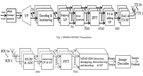
The MIMO-OFDM system for IEEE 802.11n operates at both 5GHz and 2.4GHz with an available bandwidth of 20MHz [6]. Consider (Nt,Nr) MIMO-OFDM system where Nt- number of transmit antennas; Nr- number of receiver antennas. OFDM with Nc=64 is designed for each of the transmit antennas. Nc is the number of orthogonal subcarriers. Fig 1 shows the block diagram of a MIMO-OFDM transmitter, while fig 2 displays the MIMO-OFDM receiver. The input image is either gray-scale or color. JPEG
Fig 1 MIMO-OFDM Transmitter
Fig 2 MIMO-OFDM Receiver
Vol. 2(7), 2010, 3120-3127
representation. After P/S conversion of each OFDM symbol, the transmitted signal x[n] enters the RF front end of the transmitter and transmitted through the channel. The Nr-dimensional received signal y[n] is fed to the RF front end where A/D conversion is done.
y = Hx + n (1)
where y is Nr-dimension received vector, H is (Nr x Nt )dimension channel matrix whose elements are independent and identically distributed zero-mean complex Gaussian random with unit variance, x is Nt dimension transmitted vector, n is Nr dimension AWGN vector whose elements are also independent and identically distributed zero-mean complex Gaussian random with variance 0.5σn2.
After removing the cyclic prefix, Nc-pt FFT is taken for each of the n time-domain received signal; n=1,2…Nr. The detection and decoding block performs decoding on a subcarrier basis for each of the received signal. This block performs detection, demapping, deinterleaving and decoding. The decoded binary data from each received antenna is multiplexed into a single serial stream. The bitstream is arranged and decoded to retrieve the transmitted image.
3. Modulation Schemes
The performance of the system depends on the modulation scheme. Modulation of data is also referred to as mapping to a constellation. Various modulation schemes like BPSK, 4-QAM, 8-QAM, etc are compared. As the no. of bits per constellation symbol increases, the points in the constellation diagram are closer. This results in more errors in detection as the no. of bits per symbol increases. Simulation results prove the above fact. BPSK modulation is employed in this paper as this is the most robust of all the PSK modulation schemes since it takes the highest level of noise to make the demodulator reach an incorrect decision. However it can modulate only one bit/symbol and so is unsuitable for high data rate applications when bandwidth is limited. The general form of BPSK follows the equation (2)
Sb (t) = (2Eb/Tb)½ cos (2П fct + Π (1-i)) , i=0,1. (2)
The two phases are 0 and П and the binary data is conveyed as
s0 (t) = (2Eb/Tb)½ cos (2П fc t +П)
= - (2Eb/Tb)½ cos (2П fc t ); for binary “0” (3)
s1 (t) = (2Eb/Tb)½ cos (2П fc t ); for binary “1”. (4)
The bit error rate of BPSK in AWGN is given as
Pb = ½ erfc ( Eb/N0)½ (5)
4. Channel Models
For WLAN environments, channel models close to real-time environment are Rayleigh, correlated Rayleigh and Ricean channels. Correlated channel is a form of Rayleigh channel where each channel stream is correlated to each another.
4.1 Rayleigh channel
The Rayleigh channel impulse response can be well-modeled as a circularly symmetric complex Gaussian process irrespective of the distribution of the individual components, if there is sufficient scattering (according to central limit theorem).
4.2 Ricean channel
Vol. 2(7), 2010, 3120-3127
f(x|v,σ) = x/σ2 exp[ -(x2 + v2)/(2σ2 )] I0 (xv/σ2) (4)
where I0(z) is the modified Bessel function of the first kind with order zero. When v=0, the distribution reduces to a Rayleigh distribution.
4.3 Correlated channel
In indoor-like environments, if the antenna spacing is the limiting design factor, then spatial correlation should be taken into account in the channel model. The following model based on this assumption is
RTX= E[(hq)H hq] ; for all q, q=1,….,Nr (5.a)
RRX= E[hp hpH] ; for all p, p=1,….,Nt (5.b)
where hq is the q-th row of H , hp is the p-th column of H. The independent narrowband flat-fading MIMO channel with spatial correlation is realized using (6)
H=RRX½ Hiid ( RTX½)H (6)
where Hiid= unvec ( hiid) is a stochastic Nr × Nt matrix with i.i.d. zero-mean unit variance complex Gaussian elements. The capacity of an Nt x Nr MIMO system is given by
C = log 2 (det (I Nr + (SNR/Nt) HHH)) b/s/Hz (7)
When spatial correlation is present [1], the capacity equals
C=log2 det(INr+(SNR)RRX ½ H(RTX½)HRTX ½HH(RRX ½)H))) b/s/Hz (8)
5. Receiver Architectures
Detection algorithms like zero forcing (ZF), maximum likelihood detection (MLD) and minimum mean square estimation (MMSE) applicable to MIMO can be applied for MIMO-OFDM as well with slight changes in the algorithm. Other non-linear techniques can be employed to obtain superior performance. Successive Interference Cancellation (SIC) is one such non-linear technique. This paper compares various detection algorithms and proposes the best in terms of performance and complexity. It is found that MLD algorithm works better than the other algorithms but its complexity increases with no. of transmit antennas and constellation size.
5.1 Zero Forcing Detector
In ZF detection algorithm, the governing equation is
WH = INt (9)
where W is a matrix that represents the linear processing in the receiver. In general, W is the pseudo-inverse of H.
W=(HHH)-1HH (10)
5.2 MMSE detector
The main point in MMSE detection algorithm is to minimize the mean squared error. The choice of W is made such that the MSE is minimized
ε2
= E[(s-Wx)H(s-Wx)] (11)
Working further on the above equation, W is obtained as
W = (αINt + HHH)-1HH ; where α = Nt/SNR (12)
5.3 Maximum Likelihood Detection
Vol. 2(7), 2010, 3120-3127
xml = arg ( min ||y - Hxi ||2 ) (13)
wherein a search is performed over all vectors xi, which are part of ensemble formed by all possible transmitted vectors. The no. of such possible vectors are
I = MNt (14)
where M is the number of constellation points.
MLD unlike ZF and MMSE does not require the criterion, Nt ≤ Nr. The complexity increases linearly with the number of receiving antennas and exponentially with the number of transmit antennas.
5.4 Successive Interference Cancellation
Non-linear detection techniques like successive interference cancellation (SIC) is combined with ZF or MMSE to perform better detection. SIC exploits the timing synchronism inherent in the system model. SIC is based on subtraction of effects of already detected symbols from the received signal vector y. The order of detection is crucial to the performance of the system. The detection algorithm consists of three main steps: (i) Ordering (ii) Interference nulling and (iii) Interference cancellation.
6. Unequal Power Allocation
In conventional power allocation scheme, the total available power is divided equally among the antennas. The power allocation is independent of channel parameters and error rate. So the unequal power allocation problem is formulated as a constrained optimization problem with the objective to minimize BER eventually. The BER expression for any modulation scheme can be estimated as
f(βl,pl) ≈ a * exp(-b*βl*pl) ; l=1,…,Nt (15) where a=0.2 , b=1.5 are constants.
(16)
pl are the primary variables and each pl is the transmit power corresponding to each stream. The constraint is on the total transmit power available is
Σ pl = Nt * Pa (17)
where Pa is average transmit power. Using the concept of Lagrangian duality to optimize the objective function , the BER expression and the constraint can be combined in a single expression as
F(p1,….,pNt)= {(1/Nt)* Σf(βl,pl)}+λ*(Σ pl - Nt*Pa ) (18)
Where λ i s Lagrangian multiplier. Differentiating the above expression with respect to each pl and equating to zero, a set of Nt equations are obtained. Solving the set of equations, a general equation is obtained for transmit power as
1 1 0 1 0 1 1 log 1
Nt
l u u u l Nt l u u u l u a l b P Nt p (19) In case one of the solutions is negative, it is recommended to apply the conventional power allocation scheme. Once the required transmit power for each stream is determined as P=[p1,p2….,pNt] , the received vector is expressed as
y = (√P1)Hx + n (20)
1 10 2 , 2
1
2
Nr
n
l n n
Nm
l
H
Vol. 2(7), 2010, 3120-3127
where P1 is diagonal matrix with nth entry of P as the (n, n)th entry of P1 . This modification to the received vector expression will ensure that optimal transmit power is allocated dynamically to each stream and hence will ensure reliable transmission of important sectors of multimedia files.
7. JPEG Compression
In this method, image compression is performed based on the DCT values of the pixels. First check whether the image is a grayscale or color image. If it is a color image then the image is converted from RGB color space to YCbCr (luminance, blue chrominance, red chrominance) color space. Then the image is split into smaller blocks of size 8x8 pixels. Discrete cosine transformation is taken for the smaller blocks of the image. The DCT co-efficients are then quantized. Each co-efficient is divided by elements of the quantization matrix which is given by
QLUM= [16 11 10 16 24 40 51 61
12 12 14 19 26 58 60 55 14 13 16 24 40 57 69 56 14 17 22 29 51 87 80 62 18 22 37 56 68 109 103 77 24 35 55 64 81 104 113 92 49 64 78 87 103 121 120 101 72 92 95 98 112 100 103 99]
QCHR= [ 17 18 24 47 99 99 99 99
18 21 26 66 99 99 99 99 24 26 56 99 99 99 99 99 47 66 99 99 99 99 99 99 99 99 99 99 99 99 99 99 99 99 99 99 99 99 99 99 99 99 99 99 99 99 99 99 99 99 99 99 99 99 99 99 ]
Zig-zag scanning of each block is done to so that low-frequency co-efficients are placed first while high frequency components come last in the array.
Fig 3 JPEG compression for color image
Fig 4 Zig-zag scanning
8. Simulation Methodology
A MIMO-OFDM system with a 4x4 antenna configuration is considered for the simulation. The available bandwidth is 20 MHz. Dividing the bandwidth into 64 subcarriers, each subcarrier is allocated a frequency of 312.5 KHz. The simulation parameters are given in Table I.
Vol. 2(7), 2010, 3120-3127
Table I Simulation Parameters
Transmitters 4
Receivers 4
Data subcarriers 52
OFDM symbol duration 4 µs Subcarrier spacing 312.5 kHz
Sampling frequency 20 MHz
Channel spacing 20 MHz
Data rate 64 Mbps
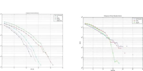
Fig 5 Detection algorithms Fig 6 Comparison of power allocation schemes
In Fig. 6, the power allocation schemes: equal, classical water filling and the proposed unequal algorithms are compared Simulation results show that BER curve for UPA is superior for higher SNR values compared to conventional power allocation.
This simulation result strengthens the fact that unequal power allocation is preferable to reduce transmission errors in applications like multimedia transmission and the value of PSNR obtained is high compared to EPA. The simulation results of JPEG transmission for different image quality are compared in Fig. 7-10.Table II and III depicts the JPEG compression using EPA and UPA and in Table IV comparison of EPA and UPA is done.
Fig.7 Uncompressed input image Received image, SNR of 7dB Fig 8 Compressed input image Received image, SNR of 7dB
Vol. 2(7), 2010, 3120-3127
9. Conclusion
Thus a comparative study of basic parameters required for a MIMO-OFDM system for WLANs is performed. The results are analysed and the best of each parameters is employed in creating a robust MIMO-OFDM system for use in WLAN. An efficient power allocating scheme based on Lagrangian dual is utilized to determine the transmit power to be allocated to each stream. A comparison of equal and unequal power allocation is also performed and the results are analysed. Unequal power allocation schemes can be utilized for efficient transmission of important parts of images with higher reliability. The combination of MIMO-OFDM and the UPA scheme considered prove to reduce transmission errors compared to the existing algorithms.
Table II: JPEG compression with EPA Table III: Unequal Power Allocation Image SNR(dB) PSNR(dB)
between transmitted and received image
128x128, color, uncompressed image
7 40
41
41
128x128, color, JPEG compression ratio 33%
7 47 48
47
Table IV: Comparison of EPA and UPA Image SNR(dB) PSNR(dB) between
transmitted(compresse d) and received image EPA UPA
128x128, gray-scale, JPEG compressio n ratio 33%
7 40 48
128x128, color, JPEG compressio n ratio 33%
7 47 55
48 55 47 56
References
[1] A van Zelst, “MIMO-OFDM for wireless LANs”, Ph.D dissertation.
[2] Albert van Zelst & Tim C.W.Schenk,( 2004), “Implementation of a MIMO OFDM-based wireless LAN system”, IEEE Transactions on signal processing Vol 52, No.2
[3] IEEE Std 802.11a-1999 , ISO/IEC 8802-11:1999/Amd 1:2000(E)
[4] Muhammad F. Sabir, Robert W. Heath Jr. and Alan C. Bovik,( 2005), “Unequal power allocation for JPEG transmission over MIMO systems”, IEEE Conference on Signals, Systems and Computers
[5] Wladimir Bocquet, Kazunori Hayashi & Hideaki Sakai,( 2006), “A power allocation scheme for MIMO-OFDM systems”, ISCCSP [6] Albert van Zelst, (2000), “Space division multiplexing algorithms,” in Proc. 10th
Mediterranean Electrotech. Conf., vol. 3, pp. 1218– 1221.
[7] BROADCOM Corporation, (2006), “802.11n: Next-generation wireless LAN technology”, White paper
[8] David Tse and PramoViswanath, (2005), “Fundamentals of wireless communication”, Cambridge University Press
[9] Khalida Noori & Sami Ahmed Haider, (2007), “Comparison of coded and uncoded vertical and horizontal layered structure for MIMO OFDM system” , ICACT
[10] J. Heiskala and John Terry, “OFDM wireless LANs: A theoretical and practical guide”, Sam Publishing
[11] K.P. Bagadi and Susmits Das, (2010) “MIMO-OFDM channel Estimation”,International Journal of Computer Applications (0975 – 8887), Volume 2 – No.3
Image SNR (dB)
PSNR(dB) between transmitted(compressed) and received image
128x128, gray-scale, JPEG compression ratio 33%
7 48