www.ijera.com 64|P a g e
Design and Simulation of a Smart Home managed by an
Intelligent Self-Adaptive System
Basman M. Hasan Alhafidh
1,3And William Allen
2 1Department of Electrical and Computer Engineering, Florida Institute Of Technology, Melbourne, FL 32901, USA.
2
School Of Computing, Florida Institute Of Technology, Melbourne, FL 32901, USA. 3
Department of Computer Engineering, College Of Engineering, University Of Mosul, Mosul, Iraq.
ABSTRACT
Home automation and control systems as basic elements of smart cities have played a key role in the development of our homes environments. They have a wide range of applications in many fields at home such as security and monitoring, healthcare, energy, and entertainment applications. The improvement of humans’ living standards make people keep trying to delegate many of their needs to a home automation system. Such a system has been built with capabilities of predicting what the user intends to do in smart home environment. However, there are many issues that need more investigation and solutions, such as: 1) many researches adopt a specific application without integrating different varieties of applications in one environment, 2) there is no study tries to show the real effect or even evaluates the implementation of predicted actions that have been established via homes intelligent gateway, 3) there is an interoperability issue due to using different kinds of home applications that have different protocols for message context. In this proposal, we will describe a new approach of an intelligent self-adaptive system that can precisely monitor a stakeholder behaviors and analyze his/her actions trying to anticipate a stakeholder behavior in the future. In addition, we will evaluate the real effect of a predicted actions after implementing them by an intelligent gateway in a simulated home environment. The principle behind a prediction process is presented by analyzing a sequence of user’s interaction events with heterogeneous, and distributed nodes in the environment using an intelligent gateway. Predicting next stakeholder action can be process using certain analytical algorithms. The main novelties in the proposed approach are threefold: I) Developing a learning technique which is embedded in an intelligent gateway to build a model of users’ behavior and interactions to balance the needs of multiple users within a smart home environment. II) Presents a novel visualization model for a home area network (HAN) based on a degree of centrality criteria, that helps an enterprise companies like Amazon, Google, Microsoft, and Xively to understand the most important services of their customers, III) The proposed system shows a high level concept of how we can design an intelligent self-adaptive system in home environment that has the capability to provide stakeholder with local services, and to support a use of IoT paradigm concurrently.
Keywords: Smart Home, Intelligent Agent, Self-Adaptive System
I.
INTRODUCTION
The new developing technology that we can see every day in computer, network and control systems make a huge change in our daily life especially with the exciting Internet Services. Therefore, Internet of Things plays an important role in managing home sensors, actuators, and devices. Any device or a piece of equipment such as multimedia, lighting, and control devices, can be connected to the home network to present new advanced services to the stakeholders.
A secure environment, an efficient comfortable data collecting system coupled with many services as data manipulating, in addition to a communication system and device automation were the significance of the idea in the design of smart
home that has been seen for the first time in the United States of America [1].
Nowadays, the definition of a smart home is a home that has different subsystems that are connected together and use their stakeholder’s information and database management. This platform make use of the connected network cabled to a computer to manage the data. In addition to that, new smart homes try to serve the stakeholder with many control capabilities from inside or outside the home. Such services include exchanging the information smoothly, mediating stakeholder lifestyle, arranging the schedule for work in the calendar, managing the security and saving money through optimizing energy consumption [1].
We can say that the new smart homes are typical module for the Internet of Things which
www.ijera.com 65|P a g e presents a very interesting field for both the academic
framework and the world industry. Figure 1, shows that the Internet of Things (IoT) has four application domains which are classified according to the type of network coverage and availability, scalability, in addition to user interactions. It also shows that the home environment is one of the IoT classified applications, which actually represents a typical example of IoT technology. The figure shows how much the domains are interconnected using the
Internet, which enables the sharing of data between tremendous providers in a smooth way to create different business opportunities [1].
Basically, the IoT framework consists of many wireless sensors and actuators in the smart field. These nodes play an important role in controlling and optimizing intelligent buildings and even smart greenhouses. In another words, using distributed nodes of sensors and actuators in the home environment in addition to an
Fig. 1: Internet of Thing Schematic showing the end user and application area based on data [1]
Optimized data management system will be done under the scope of IoT principles. Nowadays, almost all the system that are based on IoT supplied services gets much attention from the researchers and to the very big companies like Google, Amazon, Microsoft, Xively, and many more. IoT plays an important role in monitoring anything, anytime, and anywhere. As a result, such a system can precisely monitor the stakeholder behavior and evaluate the action trying to anticipate the user behavior in the future, such as monitoring elderly people in a healthy environment [2].
1.1 Smart Home Definition
Many of the scientific community do not give a precise definition about the smart homes, since some authors are not satisfied about the elements which can be part of smart home, so what can be used to easily classify this term from another. L.C.D. Silva et al. [3] define smart homes as a home-like environment that possesses ambient intelligence and automatic control. This means that a smart home has the ability to react with the stakeholder and to give different types of services classified into four types: security based services, energy efficiency based, health-care based, multimedia and entertainment based smart homes [4]. In [4], the researchers give another idea about smart
homes as The backbone which will enable the management and the control of different areas of a residence, binding four pillars of human livelihood inside a house: comfort and welfare; physical integrity and facility safety; rational management of domestic energy equipments; and the possibility to provide healthcare services to its inhabitants. The authors add that the important thing in this term is communication. Communication should be established in an easy, cheap, trusted way with a robust communication structure. So, a further definition for smart homes says Smart Home can be defined as a concentrator and discriminator of information and service. Both information and services try to provide a gateway to outdoor world services such as a smart grid side by side within the ability to provide indoor services or local functionalities to improve the level of life quality. Such a gateway will open a wider space of services by sharing the managed local information with the foreign services like smart cities.
1.2 Smart Home Services 1.2.1 Home Application Areas
www.ijera.com 66|P a g e different areas of interest, which include Security,
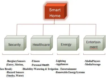
EnergyEfficiency, Heath Care, and Entertainment [3]. The Functional Organization of the smart home system as shown in Fig. 6 introduces four main categories of applications that have been supported through the building of a smart environment in our homes. It shows how each sensor, actuator, and device (nodes) in the designed system can be classified according to its functionality. For instance, we can see that the security box has many security nodes which have a similarity in its functionality like entry door sensors, motion sensors, smoke sensor, and CCTV. The healthcare box has the nodes that are concerned about personal health, in addition to elderly or disabled people. All these boxes are connected to a gateway.
Many researches present the functionality of the smart home gateway as an interface component to
collect, monitors and notifies the stakeholder about the state via specific communication technique as presented in [4], [5], [3] [6]. Further development has been proposed to not only monitoring the status but also to implement the received order that been initiated by the stakeholder himself for a current status via gateway as mentioned in [7], [8]. However, the smart gateway that has been presented by many researchers, should be designed to do a lot of work on behalf the user. These activitiesmay include but are not limited to keeping track of devices, analyzing the data, and visualizing it in the form that makes it easy for the user or a proficient partner in the application layer to monitor the status, then personally control the state of any nodes as needed to the preferred values.
Fig. 2: The Functional Organization of the Smart Home System
1.2.2 Prediction via Smart system
In general, the modern technology, which develops very fast, makes people delegate many of their needs to smart machines. These machines are focused to be built with the anticipating capabilities to predict what the users intend to do in certain environment like a smart home. In [9], the authors indicate that ” The more complex the operating system is, the more it is expected to do on behalf of its users ”. For that reason, many researchers use the artificial intelligence that involves many techniques. This technique may include analyzing the user actions from the database then do some stochastic operations trying to predict the next user action.
So the smart homes must be an adaptable and dynamic intelligent system, which means the need to adapt to the stakeholder’s lifestyle, anticipate their next activities to optimize the direct interface between the user and the home appliances. Knowing the
lifestyle of a particular user in a home requires precise knowledge about the history of appliance usage for each state in the entire environment. There are many methods to anticipate the user’s future actions like intelligent Human Computer Interaction (HMI). The principle of the prediction process is studying the sequence of interaction events to generate the next predicted user action or state [10].
In this paper, we formulate the objective of our work to:
Design an integrated system that we call the Butler, to coordinate and control sensors and devices within a smart home to satisfy the user ’s requirements and behaviors.
– Learn the behavior of different users as they interact with devices to build a model of user activity within the smart home.
www.ijera.com 67|P a g e – Utilize an agent-based system to provide
interoperability between subsystems and components so that the full range of applications provided by the Internet of Things can be effectively integrated with the smart home. – Utilize cloud-based storage of activities to
enhance long-term analysis of user behaviors. – Manage resources such as water and electrical
energy to minimize waste, and increase efficiency.
– Integrate security and privacy of user data throughout the system.
Simulate the system ’s operation to demonstrate
how the Butler will perform the tasks it was designed to achieve. This will be accomplished by demonstrating how the system will carry out a range of typical scenarios that are based on the behavior of a single individual or multiple individuals.
In summary, the paper makes the following contributions.
Design an integrated system that learns user’s
behavior and then manages the components of a smart home by controlling devices and subsystems to anticipate user’s needs.
Develop learning techniques to build a model of user’s behavior and interactions to balance the needs of multiple users within a smart home environment.
Develop a simulation of the operation of the smart home to demonstrate how the user’s behavior can be modeled, and how the various components and subsystems can interact to achieve the user’s needs.
Present a novel visualization model for each subsystem in the network based on the degree of centrality criteria.
The rest of the paper is organized as follows. Section 2, discusses related works. Section 3, describes our novel design for intelligent home automation system based on IOT design pattern. Section 4, discuss the implementation and result.
II.
RELATED WORK
By 2025, Internet nodes based on IoT application domains and related applications as shown in figure 3, reside in everyday things such as food packages, furniture, paper documents, and many more [11]. The solution to interface such huge number of things is to design a gateway that has the ability to communicate with all heterogeneous devices that have different communication technologies. Control4 by Control4, home gateway by STMicroelectronics as mentioned in [11], are good projects which enable the stakeholder to monitor the devices at home. They also add the capabilities to remotely control any managed device in home. Therefore, this gateway nowadays, is the basic element in the IoT principles to enable the second step in which virtualize every device in the cloud, finally is to apply many analytics using different analysis applications and platforms to manage and optimize the use of the devices in the smart home environment.
Furthermore, a wide range of research proposed on the design and development of smart homes has been carried out in the worldwide by many researchers. Systematic literature researches have been followed, in order to study the existing systems.
www.ijera.com 68|P a g e In addition, there are ongoing researches,
which investigate the exploration of the intelligent home monitoring systems to determine of Energy Optimization, Health Monitoring, Entertainment, and Security.
Integrating the four classified applications to construct a general framework at smart home environment has been proposed by Mendes at el. as in Figure 4. This framework uses a local communication infrastructure that consists of two main components; the first one is a Home Area Network (HAN) that divided to Body Area Network (BAN), Personal Area Network (PAN) and WirelessSensor Network (WSN); while the second part is a Home Gateway(HG), which has been represented as a M2M interface. The authors indicate that the HG represents a universal multi-purpose device, which assures the interoperability between different types of a home applications. In
other words, the gateway plays an important role to process the verity in data type, in addition, it connects the home’s inner infrastructure to the outside world. The outside world is represented by Cloud, where the collected data is being forwarded to, beside the data classification and processing for further aims. The system presents a good approach based on smart cities platform; however, the stakeholder stills need to interact with devices manually. The second issue is the complexity of M2M gateway, that is needed to interface all diverge services’ platforms by saying” M2M wireless networks can help to increase the production and efficiency of machines and to improve the safety and reliability of complex systems but the main concerning issues in these M2M service networks come from the vertical fragmentation and complexity of M2M markets” [3].
Fig. 4: Smart home devices accessed through global network framework[3]
III.
SYSTEM DESIGN
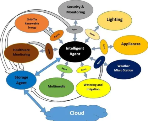
Our proposed system as shown in Figure 5, tries to enhance the design of the smart home environment by introducing a novel approach represented by using a smart agent for each subsystem, a storage agent with the cloud for backup data with an enterprise analysis, and the central intelligent agent (Brain) that connects all the
www.ijera.com 69|P a g e The following paragraphs discuss the
necessary steps to present our intelligent system. These steps include the requirements analysis of the system, system design, the architecture design, finally the implementation of the system via NetLogo simulation program.
3.1 Requirement Analysis
The requirements of the entire system are divided into two major ones, which are the stakeholder requirements and the system requirements. We explain each of them in detail as follows:
3.1.1 Stakeholder Requirements
These requirements simply show what the stakeholder wants to achieve through the use of the system, like delegating most of the user needs to the automated system, which may include but is not limited to:
a. Providing a secure environment to live in against burglary using the surveillance which will be 24/7 by monitoring the outdoor and indoor suspicious activities.
b. Providing immune environment against fires, smoke, and carbon, gas leak, bursting pipes, leaks, and floods.
c. Having the lighting system be fully monitored and controlled via the system.
d. Monitoring and controlling all the appliances in home and providing the appliances status at any time.
e. Knowing the current weather status, and weekly report about the weather and future concerns such as storms and hurricanes.
f. Monitoring and controlling all the multimedia devices in home with all the available capabilities that are provided by the devices.
g. In case of handicapped people, having the system understand what the user intend to do by helping them to do that.
h. Optimizing electrical water resource consumption to reduce both electrical and water bills
3.1.2 System Requirements
From the section above, we can conclude that the system should have the ability to interface with any electrical and electronic device in the home. It must be capable to communicate using a verity of different standard communication protocols to provide interoperability. It is easy to maintain. In addition, it has the ability to collect the data from the environment at any time then analyze this data to make a decisions depending on similar hypotheses from previous rules. In another words, the system has the ability to self-learn, be autonomous and adaptable to any change that could happen by user behavior in any time at any place in home. So the system tracks the behavior of
each user, stores and retrieves the behavior to/from the short (Local) term memory and long (remote) term memory in the cloud. Finally, the system should provide different types of user interfacing like, touch screen unit, microphone for voice command, internal speaker, and have the ability to send/receive SMS or MMS to provide more reliability to the designed system.
In the following paragraphs, we start building our proposed system through the discussion of what each part of the system should do to meet the stakeholder requirements. Referring to Figure 5, the design shows all the necessary components of the system which includes subsystems, agents, and Intelligent Agent (IA). Each component has its own independentrequirements. To make it easy to understand how the entire system requirements satisfy the stakeholder ’s requirements, we prefer to start our discussion with each subsystems requirements, then the agents’ requirements and ending with the intelligent agent requirements that represent the brain of the proposed system.
3.1.2.1 Subsystems Requirements: The subsystem may contain different kinds of nodes like sensors, actuators, and devices. Because each subsystem deals with specific kind of nodes, the requirements for each subsystem will differ from the other subsystem. The following paragraphs briefly discuss two subsystems requirements as an example of an independent system.
1) Security and Monitoring Subsystem Requirements
Each kind of security sensor has its particular use among other sensor for example, motion, smoke, window break sensors. So, the security and monitoring subsystem should provide a secure and safe place for the resident to live in through monitoring and controlling these kinds of sensors. Thissubsystem plays an important role in the entire system because it affects the work of the other subsystem indirectly as discussed later.
2) Lighting Subsystem Requirements
This subsystem contains both indoor and outdoor lighting components that are connected to the lighting subunit. The main functionality here is to monitor and control all theconnected nodes within the subunit, then send the status or receive a command using the lighting agent. As a result, this subsystem gives the IA the ability to manage all kind of nodes in the easiest way to provide a much more convenient environment and energy efficient use if we compare it to the standard lighting system in our homes.
www.ijera.com 70|P a g e agents play a very important role between the
subsystems and the IA in the center. It’s simply represents a context information layer where a context model created using some context modeling technique, such as Key-Value, Mark-up Scheme, or Logicbased. It provides a uniform representation of nodes’ context information to the IA; therefore, each agent works as an interpreter residing at this layer. In general, the common requirements for each agent should be as follows:
1) Communication with Subsystems
a. The communication can follow any standard communication protocol, with the most common protocol in the market like weave, X10, ZigBee, and Bluetooth.
b. The communication protocol type that the IA follows will depend on the subsystem’ preferred type of communication protocol. So every
communication between the IA and its subsystem are completely independent of what other subsystems have.
2) Communications with IA
a. The communication can follow any standard communication protocol, by using the most common wired/wireless protocol in the market like weave, ZigBee, and Bluetooth.
b. The communication between the IA and all the agents should use a unified context messaging protocol for creating the message context (Context aware message protocol). So all the agents should follow some necessary steps to construct a unified messages contents to be send after that to the IA. Which implies that there is a filtering process for these data, which discussed in the following point.
Fig. 5: The Intelligent Home System Design (Project BUTLER)
3) Filtering of input data and/or input events a. The filtering done on the agent is based on what
the IA needs.
b. Use a time-based process to record the data/status of connected devices in certain log files.
c. After collecting a large amount of input data or input events from a subsystem, the agent should try to filter the data to get some information from this data.
d. Send the observed information (change in the event) to the IA using the unified context messaging protocol.
e. When transferring a large amount of data, this agent should communicate with another agent (Storage Agent) that receives a series of raw data and transmits it to the cloud to be stored, classified, and managed when it necessary. 4) Security for communication
www.ijera.com 71|P a g e b. When the agent reports a new information
message to the IA or receives a new command from the IA, this agent should use its own subsystem address and IA address.
c. When the agent reports data to the IA, this agent should use its subsystem address as a source address and the storage agent address, not the IA address, as the destination address.
d. The collected data should follow one direction when transferring the data or status to the cloud. e. Has the ability to receive any order from the IA
and respond back using push command services or pull command services.
3.1.2.3 Intelligent Agent Requirements: As mentioned in the previous paragraph, the IA represents the brain of the entire system and plays an important role for our design. Many functionality has been delegated to this agent like performing reasoning process over predefined rules in addition to decision making process to generate new rules according to context information and related output action for current status; therefore, its requirements will be distributed to several points as follows:
Fig. 6: The Five Sense Organs in Human Beings [12]
1. Communication with IA/subsystems
a. The IA should work as a central unit in the home. b. It records and monitor the user behaviors or
external behaviors like weather behavior.
c. The communication between the IA and subsystems should be done via a specific agent for each subsystem. Therefore, each subsystem has its own agent that is completely isolated from other agents from other subsystems.
d. The IA should specify the IA effects on its working, which means that the agent should do the filtering process based on the IA needs. For instance, the IA needs to know when and what any change of status is that happens to the current status of any sensor, actuator, and device. The IA does not care about the continuing reporting of the light, as an example.
e. It should have connected to all the subsystems by using a different standard communication protocol via the agents.
f. The IA should use some security protocols like (Private /Public Keys) to secure the connection between the IA and the agent, so the IA should have its own Private Key and each agent has its own Public Key.
g. The IA should have the ability to communicate with each subsystem ’s agent using a standard language protocol.
h. It should follow the same context messaging protocol (Context aware messaging protocol) to all the agents from different subsystems.
2. Learning User’s Behavior Patterns
www.ijera.com 72|P a g e a. Record user activities in specific log files for
further analysis, like making new rules or modifying old rules.
b. Provide context awareness capabilities.
c. Make decisions and prediction based on past behaviors and new inputs.
d. Provide different priorities according to the type of status and users. For example, some users have a higher privilege level than others or some event is more important than other changes.
3. User Interface
a. The IA should have several user interface techniques. These techniques include audio, visual, gesture, authentication, and configuration by the owner. As an example, the IA will execute a new command made by a defined user via listening to any voice command or touchable keypad command via IA ’s display unit.
b. Provide voice, face, and gesture recognition techniques.
4. Storage of data from long-term and short-term activities
a. The storage memory has enough capacity to record the data that comes from long-term and short-term activities.
b. Backup data is used to save the data and information in log files in one of the common cloud servers in the web.
3.2 System Design
3.2.1 The Overall Design of the System
To manipulate all these requirements, the design of the system will consist of eight subsystems in addition to the central Intelligent Agent Unit shown in Figure 5. Each subsystem has different kinds of sensors, actuators, and devices which we call ’NODES’. For each subsystem, all the nodes should be connected to the subunit of that subsystem. For example, the Multimedia Subunit connects all the multimedia devices in the home. In addition, every subsystem has an independent agent. This agent plays an important role in communication between the subunit and the central Agent (IA). Every agent can communicate with its subsystem using the same message language protocol that this subsystem uses. The language protocol between the IA and all the agents will be the same whether the communication protocol is wire or wireless. The central IA connects all the subsystems as one network, which is shown in Figure 5. This IA, as we compared to the Five Sense Organs in Human Beings in Figure 6, represents the brain of the automated system that continuously works to track the user’s behavior by saving the information in the database, minimizing then analyzing the data to get the information. After producing some information
about the preferences of user, the next important point is to predict the user’s needs and act on behalf the user himself/herself to do the delegated action.
Now, to know how the specific design that discussed above meets the system overall requirement. Figure 7, shows the architecture design of the two suggested subsystems that communicate with the IA who control and manage the message flow for all the messages coming from or going to any subsystem.
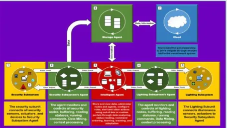
From Figure 7, we can clearly see that each subsystem has its own specific nodes which differ from other subsystem; hence the security subsystem has many types of nodes such as motion, smoke, door lock, window break, or CCTV, while the lighting subsystem has different kinds of nodes like illuminance sensors, lighting bulbs, and LED. All these nodes are connected to a security subunit. The subunit connects all security sensors, actuators, and devices to a security subsystem agent using either wire or wireless standard communication protocol. It is important to mention that there are many tasks assigned to each agent which also differ from one agent to another. These tasks may include monitoring and controlling all security nodes, buffering, reading statuses to send them to the intelligent agent, running predefined commands from IA, doing some data mining and context aware processing.
www.ijera.com 73|P a g e the system’s extendibility much easy to perform. The
IA here plays the most important role between the butler ’s components. It is basically the brain of the designed system. This brain has a lot of work to do like connecting all the subsystems agents and the storage agent with the cloud to the central unit. It must be reactive, autonomous to take the control over the other subsystem through self-learning, flexible, and adaptable to user behaviors. The storage agent here proposes a firewall agent. It can be supported with firewall capabilities as a security supported agency or isolation gateway to perform a specific task like isolate the inner environment (home environment) form outer environment (cloud system).
3.2.2 Comparison between Mode of Operation (Manual Mode and Automatic Mode)
The manual mode here means the direct interface between the user and the node itself or what we do every day in our daily life, in another words, using the regular nodes and electrical outlet that we are using every day that have nothing to do with the smart environment like a tungsten lamp plugged to simple electrical outlet or any appliances like regular HVAC system. The Automatic mode represents the mode where the butler is being used in the same environment to do some jobs which have been delegated to the butler by the stakeholder. Doing the job in an efficient way demands using some type of artificialintelligence. To reach this level of intelligence, this mode has two previous steps that must be implemented before reaching the current level. Section 3.2.3 discusses these steps in detail.
3.2.3 System Development Phases for Automatic Mode of Operation
The automatic mode needs a much more complex system than the simple system in the manual mode. This system is divided into software and hardware components. The hardware component includes the agent for each subsystem, the storage agent, the IA, and the cloud based system. The software component of this system should support both standard wire and wireless communication protocols, the necessary preconfigured software programs for each agent, in addition tothe operating system for the intelligent system.
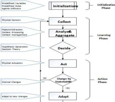
The automatic mode of operation, as shown in Figure 8, has three phases: Initialization Phase, Learning Phase, and Action Phase, as discussed in the following points.
1) Initialization Phase
This phase includes all the initialization parameters for the nodes and the related subsystem agent software programs for each agent, in addition to the intelligent agent itself. The initial parameters and software programs are necessary when any part of the system needs to berestarted or rebooted. Many of the parameters and rules that are presented as initial rules for operation from the starting point are actually present the default rules that any system begins with. Adding to that, several standard flowcharts are discussed in detail in the system architecture section (Section 3.3). These flowcharts are the preliminary procedures that the intelligence is going to use when certain events occur at any time, such as alarm detection, rainy weather and so on. All these configurations are necessary to begin with the next step orwhat we called the learning phase.
www.ijera.com 74|P a g e 2) Learning Phase
This represent the second phase of the automatic mode of operation. It consists of four essential steps that begin with collecting the status for each physical node from all the subsystem agents in the IA local memory. The next step is to analyze and aggregate the information that comes from the agents using some feature extraction, context processing and context management. The decision step presents the use of decision theory that be used to generate the hypothesis for current inputs. The hypothesis here represents the target function that the IA want to model for the input information. If this hypothesis is new for the IA, then the IA should wait for the user to take an action. After this step, the IA can build or
generate a new rule to use it in the future for the same hypothesis. If the current hypothesis is similar to a hypothesis that exists in the local memory, then the IA should act depends on the user demands.
This phase is a very important because it tries to build a new rule that consists of several input variables coming from node statuses and the output, which mean the stakeholder’s action according to that input. The strategy to build new rules comes from tracking the user behaviors against different nodes statuses in the surrounding environment and to implement these rules in the last phase of automatic mode. The new rule is used along with the initial rules to take control of the system on behalf of the user on the next phase.
Fig. 8: The development phases for the automatic mode during the active mode of operation
3) Action Phase
In this phase, the IA tries to take the right action using the applicable rule for the current state or node status. This action is represented by the Act block in Figure 8. The last block is labeled in Adapt which means that the IA should have the capability to update the learned rules from the previous phase due to an unexpected change that has been done by the stakeholder manually. In another words, the adaptation here means the changing or editing process for the produced rules in the previous phase that the IA should follow. These changes are actually due to the changes in user behavior (the output variable for the target function) for the same input node statuses (the target function’s inputs variables). It’s important to mention that this adaptation happens after the IA detects the same user action three times concurrently.
www.ijera.com 75|P a g e 3.2.4 The Configurations in the Automatic Mode of
Operation
From our daily life, everybody know that the human life naturally and continuously is changing from time to time, but after a precise look at these changes from a different angle, it would be clear that there are huge similarities in these changes which happen on a timely basis. Therefore, we present our system to work in a different mode. Each mode has its own configuration during the design phase. So, our intelligent system provided with a configuration for active mode and standby mode. Each mode will contain different preinstalled rules, which seems to be logical for what the people need in their daily life.
3.2.4.1 The Configurations for Active Mode: a. Security and Monitoring Subsystem:
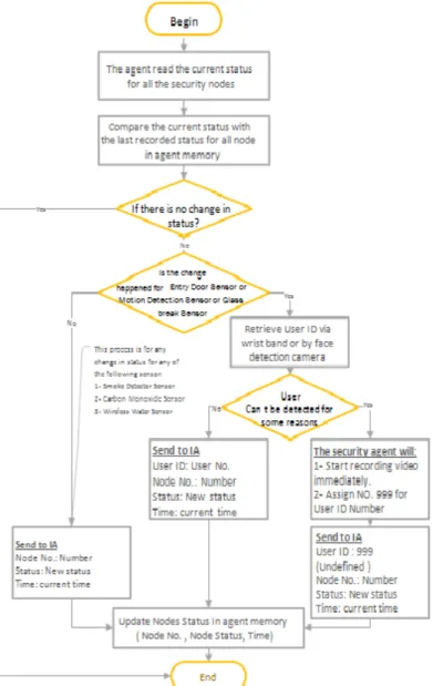
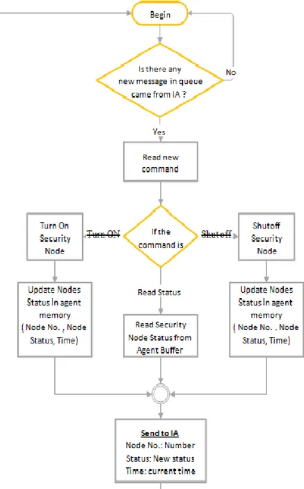
The configuration for this subsystem consists of five important algorithms listed as flowcharts to make them easy to follow. Figure 9 shows how the agent reacts when monitoring any changes could happen for security nodes, while Figure 10 shows how the agent listen to the IA in case of any new command has been ordered by the IA to be implemented in the security subsystem.
Figures 11, 12, and 13 show concurrently the algorithms for monitoring an opened access door for more than the predefined 15 minutes, the security subsystem response to IA reply related to the opened doors, and the steps that need to be implemented after the IA responds to alarm activation and new user detection at home. The complete steps for each algorithm are clearly discussed in Appendix A.
www.ijera.com 76|P a g e b. Lighting Subsystem
Usually, the time of day and the weather in this subsystem play an important role but after deep consideration of the working scenario, we decided to depend on the illuminance level in home due to better performance and efficient use of energy consumption. In other words, there are several algorithms that contain several predefined rules, as summarized in Figure 14, and 15.
c. Appliances Subsystem
The appliance subsystem agent has two main algorithms. The first one is about monitoring any appliances then notifying the IA with the new status for further actions, while the second algorithm discuss on how the subsystem agent will react upon receiving an order from the IA related to the last status or in different situations like changing the state of any node or reading the current status. In some cases, like turning the HVAC on, the agent here should check to see if the command has a user preferred value or not and then finally send the new status of the node back to IA.
www.ijera.com 77|P a g e The algorithms here are preconfigured to do
much of the monitoring process for the aggregated data that the system preserved from the micro station. Monitoring all nodes continuously and notifying the storage agent of all nodes’ status every 10 minute, then the later should send the information to the cloud as a backup data. In addition, the agent monitors the chance of rainy day or a nominal weather conditions to notify the IA, so the stakeholder will be aware of such status and ensure his or her personal safety. Further details are added in Appendix A.
e. Watering and Irrigation Subsystem
The irrigation system plays an important role in this subsystem. The watering schedule for the landscape will work depending on the feedback signal generated by the distributed moisture sensors planned in the landscape and the probability of a rainy day during the next day time period. Any changes in the subsystem will be sent as a notification message to the IA for further analysis.
f. Multimedia Subsystem
The preconfigured rules for this subsystem are limited to monitoring any changes for any node, applying any command that comes from the IA, finally notifying the IA about a change in any nodes status.
www.ijera.com 78|P a g e Fig. 12: This thread work after receiving a reply message from IA related to opened doors
Fig. 13: Security response to alarm message from IA to activate emergency state or to add new user to the system
g. Healthcare Subsystem
Notifying the IA for all nodes status every predefined period of time is the first step for the monitoring algorithm. The second task for this subsystem is notifying the IA in case the agent detects any a nominal condition for the stakeholder. In that case, the IA should receive an attention message indicating that the stakeholder needs attention due to a nominal health condition detected by certain node so he can take further actions as discussed in details in Appendix B.
h. Grid-Tie Solar Energy
The needed configuration for this subsystem agent is centralized upon monitoring the overall status of energy nodes like current power source, average power consumption, charging status and battery status. The monitored nodes status should be sent to the IA and storage agent for further action. In addition to scheduled monitoring, the agent sends a notification upon a specific condition or a nominal state to be analyzed in the IA. The detailed algorithm is discussed in Appendix B.
3.2.4.2 The Configurations for Standby Mode: This mode will be activated via the stakeholder when he
www.ijera.com 79|P a g e electronic device in the home. Therefore, the
important steps must be done by the IA when this mode be activated. The flowchart 16 clarifies all the steps that need to be taken in the standby mode. Figure
16- (A) shows the flowchart to enter the standby mode and the delegated steps for IA to do, while Figure 16-(B) shows the IA monitoring flowchart to monitor any update due to any node status change.
Fig. 14: This Process is done by Lighting Agent during learning and after learning phase to Monitor any change in status and Report the new Status to IA
From Figure 16, as soon as the IA receives a command message to command the butler to enter the standby mode, the IA reads the initial values for the standby mode from its local memory to send it to every subsystem via its agents. After that, the IA keeps looking for any changes that could have happened in any node or subsystem as mentioned in Figure 17, to notify the stakeholder about it. For instance, if the IA receives a status message from the security agent that reports some abnormal action in some security nodes for example, one of the windows is broken, or the smoke detector was activated, are considered critical cases here. If the IA finds the
www.ijera.com 80|P a g e Fig. 15: The Lighting Control Thread
3.3 System Architecture
This section discusses the proposed Butler architecture, which is represented by a distributed network that has different types of components to construct the designed system. Each similar type ofcomponents to construct the designed system. Each similar type of node use has been classified within an independent subsystem and the way each subsystem is connected to the IA in the center throughits own agent as well as the way the system is connected to the storage agent and the cloud based system for future data analysis and management. Figure 18 represents the Butler Architecture.The architecture shows that each subsystem has its own agent. The agent here has many embedded threads that do different tasks simultaneously, like a security thread for the alarm message response, or security thread for monitoring; Therefore, different functionalities of preprogrammed threads need to be embedded inside the agents to represent the initial procedures during the automatic mode of the life cycle operation .These initial procedures that we already discussed in Section 3.2.3, have preprogrammed rules and a data set that each
agent should follow during its work. As shown if Figure8, these threads work from the first phase of operation because they have the rules that the system must use as initial rules.
The following paragraphs discuss an example that explains how the interactions are done between more than one agent and the IA agent based on necessary preprogrammed threads. The example gives a scenario about when the motion sensor in the security subsystem detects a person moving in the bedroom in early morning. Therefore, each subsystem has different types of missions to do as part of our eco-system. In another words, many tasks have been distributed to different agents to construct a distributed embedded system. This infrastructure proposes a novel design for intelligent home design called the Butler, which tries to facilitate human life in our modern world through monitoring and autonomous control of the connected nodes in the entire environment.
www.ijera.com 81|P a g e any detection of a new status that differs from the last
status which recorded in the agent’s local memory. The second step depends on the type of sensors, because some sensors like entry door, motion, and glass break sensors need further actions to be taken by the agent. This action is to know who causes the
event’s changes. If the agent detects a defined user ID by using a wristband or face recognition technique, then the agent will send the user ID’s and the sensor ID with the new status to the IA. If the agent cannot define the user, then it will send the same information to the IA but with user ID’s number equal to 999.
Fig. 16: Standby Activation and Monitoring Flowcharts in the IA
Fig. 17: IA response due to security alert at standby mode. This IA thread work after receiving a message from security agent related to status change in Smoke Sensor or Carbon Monoxide Sensor or Wireless Water Sensor
or glass window or access doors lock or motion sensor AND standby status is ON Sending the status with the user number 999
means that the current user is undefined to the system.
www.ijera.com 82|P a g e back to check for further changes in any security
nodes’ statuses. It is important to mention here that this thread is embedded in the security agent itself, which means that the IA does not need to keep it busy all the time. Trying to track any change could happen for a large number of security nodes in the designed system. Moreover, there are a lot of if statements and functions need to be split from the main program in the central agent to create a weight balancing and to have some type of robustness.
The flowchart in Figure 17, represents one of many threads that are embedded in the IA which has a particular job to do. This IA’s thread works to handle a new report message from the security agent related to a change event in one of the motion sensors in the security subsystem. The IA continuously keeps track of any new message that comes to the local status buffer, then checks the node number of that sensor. It determines whether the related number refers to motion sensor or not. If not, then the process goes back to check the buffer again. If the node number refers to motion node, then the next step is to check the node status. If the status means that there is no motion in that area anymore then the butler should initiate an order to turn the light and HVAC off in the area where is no motion is detected anymore. On the other hand, if the status indicates a movement in the area, then the IA must check if that user is defined to the system or not. If the user is well known, then the IA initiates an order for the lighting agent to make the illuminance of the preferred level for that user. In addition, it initiates another message order to turn the HVAC on the preferred temperature for the current user. In case the IA cannot identify the user for some reasons, the IA initiates the same order message but with initialized level values for each lighting and HVAC temperature level.
So, Figure 15 in Section 3.2.4.1 explains the process that must be done by the lighting agent to implement the new command that comes from IA; then it reports the new status to the IA. So, when the lighting agent receives an order to turn the light ON for some node, the agent measures the illuminance level in that spot. If the level is under the user preference level, then the voltage for the lighting is increased by a manually predefined 10 Volts. In other words, the agent does a closed control loop to modify the voltage supply until it preserves a +/-0.05 from the preferred illuminance level for the user in the area. When there is no motion any more, the lighting agent should receive” shut off the light” from the IA. In this case, the lighting agent should wait for a manually predefined time period of 120 secs and make sure that the last command is still the same to shut off that light
or do something else, like keep the light ON or read the status. The significant benefit for setting the manually predefined time period 120 sec delay is to prevent the instability of turning the light ON and OFF during a short period of time, which means preventing the lighting from over reacting.
Table 1 shows the indirect interaction between each subsystem agent and other components through the central IA. The green arrow means that this agent is affected by the other information that comes from other components; for instance, the lighting agent will turn ON some light due to the security notification about the motion by a user in the home. The blue arrow means that this subsystem has the effect on another component due to event change in one of its nodes. For instance, the stove is turned ON while the system is configured to work on standby mode, then the security subsystem should take further actions to prevent any damage that may occur inside the house.
Some components like the weather agent, are not affected by any event change which may occur in each of the security, lighting, and appliance subsystems. On the other hand, we can find that some changes in the weather subsystem affect the work of many subsystems in one time. For instance, if there is a strong weather condition like a hurricane or a big chance of lightning, then the security subsystem should close the opened doors and windows. In addition, the lighting subsystem should turn off the unnecessary lights and appliances trying to make the home a much safer place during an abnormal weather conditions.
3.4 System Simulation
www.ijera.com 83|P a g e Fig. 18: The Intelligent Home System Design (Project BUTLER)
Table 1: The indirect interaction between each agent and other system components
IV.
RESULTS
4.1 Home’s Environment Representation via Net Logo
After assigning all the requirements and necessary design for all the needed components of the proposed system, the NetLogo 5.2.0 simulation program was used to simulate the home environment and necessary hardware components. Figure 19 shows a map as an example of a simple home plan. The home consists of one bedroom, bathroom, living
www.ijera.com 84|P a g e Fig. 19: The Designed Home Plan using NetLogo
The setup button, which is labeled with number 1, is used to set up the nodes in the home environment to the initial state, while the run button labeled with number 2, is to execute the software program infinitely. The standby mode button, labeled with number 3, is to choose between two types of configurations, the active mode configuration and the standby mode configuration. Because of the different procedures between each mode, we can choose the first mode when the user at home, otherwise, we choose the standby mode when the user is out of the home. By the manual mode button, we can select between the manual mode of operation and the automatic mode of operation.
The manual mode here represents what we have in our home and how we control the nodes in our daily life. In another words, this mode neither has any agents for each subsystem nor an Intelligent Agent, as what we have in the auto mode. Therefore, the control process for any node must be done by the user himself/herself through a direct interface.
The automatic mode represents the automatic mode of system operation, which include the using of an agent for each subsystem, the central Intelligent Agent as the brain of the automated system and the cloud as a backup for the entire system. As discussed in Section 3.2.3, this mode consists of Initialization Phase, Learning Phase, and Adaptation Phase. Therefore, the butler here should take control of the nodes during the operation in this mode. However, it is important to mention here that if the user tries to change the status for any nodes in the environment for some reason, the butler should give the user the higher privilege to execute what the user needs. At the same time, the butler tracks the user behavior, so if the butler sees that the same action happens several times upon the same input states or sensor values, then the butler should be adaptable by building or editing the current rule for that status in the database that exists inside the IA. Section 4.2, discusses in more detail
what the butler does during a certain time of a weekday when choosing the automatic mode of operation.
The manual control for any node during both manual or auto modes are done via the buttons labeled 5, 6, 7, and 8 in Figure 19. Some of the nodes’ statuses are Boolean values, which mean the nodes are either on ’ON’ state or on ’OFF’ state, like TV, voice mail device, coffee maker, smoke detector sensor, or windows break sensor. The other types of nodes hold analog values such as dimmer switches for the lighting in each of bedroom, bathroom, kitchen, and so on. Each node is displayed in the home plan with red color to indicate the OFF status, while the green color indicates the ON status.
The landscape has the sprinkler-motor button labeled number 6.This button turns the sprinkler motor ON in four areas around the home. Each area has two sprinklers in addition to one soil moisture sensor. The soil moisture sensors are only used in the auto mode. This means the sprinklers in the manual mode work based on a fixed timing schedule such as the standard watering system that we can find in our home.
4.2 Morning Scenario
www.ijera.com 85|P a g e his breakfast. In the kitchen, the user also would turn
the light on and try to make fresh coffee and some light meals using the range or oven as shown in Figure20. After finishing the breakfast at 6:45, the
user goes back to his bedroom again to change his clothes. Finally, he leaves the house for work at 7AM as shown in Figure 21.
Fig. 20: Morning Time Scenario at 6:18AM
Fig. 21: Morning Time Scenario at 7AM
Dealing with this simple scenario makes the power resource calculation clear and easy to understand because the same steps are used to explain how the automatic mode works to predict the user behavior and try to work on behalf the user to execute the delegated tasks.
The following paragraph discusses how the calculation has been done for both water resources and the electrical power resources.
4.3 Energy Monitoring for Electrical Consumption and Water Usage
This section describes how we calculate the electrical power consumption and water resource usage as well. Table 2 shows: the number for each node that are used in different scenarios, in addition to node’s name, related subsystem, status values,
www.ijera.com 86|P a g e Table 2: The classification and related information for each node in the proposed system
The energy E in kilowatt-hours (kWh) per day is equal to the power P in watts (W) times number of usage hours per day t divided by 1000 watts per kilowatt:
E(kWh/day) = P(W)*t(h/day)/1000(W/kW)...(1)
To calculate the energy consumption for nodes that the user may use every day, we can use Equation 1. Therefore, as we are working in the manual mode, we calculate the average power consumption for daily usage during the morning scenario period only from 6AM to 7AM. We find the electrical power consumption to be about 0.630 kWh in the weekday. So, the electrical power consumption for one month based on this scenario only will be 18.9 kW and for one year is about 226.8 kWh for a morning scenario only.
To calculate water consumption of four landscape’s zones, we assume that a water pump motor scheduled to run for 30 minutes per cycle, 3 days a week as follows:
No. of Gallons/Cycle = (No. of Gallons/Min/zone) *(time for each zone)... (2)
So, by applying equation 2, we have 360 Gallon/cycle = (12 gallons a minute per zone) * (30 Minute/zone). For four zones, the water consumption is 1440 Gallon/Cycle which produces 5760 gallons per week. Therefore, the monthly water consumption is 23040 Gallon a Month, which represents a large number that reflects a large utility’s bill each month.
4.4 Standby Mode Scenario
In this section, we discuss how the butler is going to react due to any nominal conditions that may happen in any time when the user is a way from home and the standby mode activated. Figure 22, shows how the Butler must act according to change in status for some security nodes like access door, window break, and smoke detector sensors. Hence, the current mode is on Standby Mode. If the carbon sensor detects smoke inside the home, then the IA instantly should do several steps. These steps include sending a notification message to the owner, turning all lights ON, recording a film using CCTV. activating the alarm, then calling 911 as labeled in red.
4.5 Network Analysis
www.ijera.com 87|P a g e a. Number of Nodes (order) = 8
b. Number of Edges (size) = 23
Further studies, can be done through representing each node in this graph by a clusters. Each cluster has its particular sensors, actuators, and devices. So, in this way of representation, the graph will give more specific detail that related to each sensor in the entire network and real values of the degree of centrality and clustering coefficient in the network.
V.
WORK PLAN AND IMPLICATIONS
From the sections above, we have already discussed the difference between the manual mode and automatic mode with the active and standby related configurations. The active mode presents the morning scenario for a person who wakes up and
prepares to leave for work for one hour. However, there will be a different scenario when the same person comes back from work. So, a new scenario must be developed to show different kinds of nodes used for different stakeholder needs.
The results of how the user is going to interface and deal with many nodes in the manual mode was already discussed. The next step is to apply some machine learning technique inside the IA to predict the user behavior for different scenarios, including the morning scenario, then apply this prediction to see the total effect on the resource power consumption and user’s daily behavior. As a result, we can compare the electrical power and water resource consumption. In addition, we will try to validate all the Butler’s decisions and its work to track and anticipate the user’s actions during more than one scenario.
Fig. 22: Standby Mode Scenario during Alarm Activation
www.ijera.com 88|P a g e Extending the Butler capabilities to deal
with more than one user (Multi User Interface) is the final goal in our work. Trying to deal with more than one user is helps us to simulate an intelligent system that has the ability to work with many different stakeholders inside one environment. The latter case reflects what people are doing in their
daily lives, so the Butler should be more realistic for the real world applications.
VI.
APPENDICES
A Subsystem Configuration Algorithms
This appendix will discuss in detail the necessary configuration algorithms for each subsystem as follows:
1. The necessary steps for security and monitoring subsystem algorithms as an initial configuration for the security agent.
www.ijera.com 89|P a g e 3. The necessary steps for Lighting Subsystem algorithms as an initial configuration.
4. The necessary steps for Appliances Subsystem algorithms as an initial configuration:
5. The necessary steps for Weather Micro Station Subsystem algorithms as an initial configuration
www.ijera.com 90|P a g e 7. The necessary steps for Multimedia Subsystem algorithms as an initial configuration
8. The necessary steps for Healthcare Subsystem algorithms as an initial configuration
REFERENCES
[1]. L. Sun, H. Ma, D. Fang, J. Niu, and W. Wang, Advances in Wireless Sensor Networks: The 8th China Conference, CWSN 2014, Xi’an, China, October 31– November 2, 2014. Revised Selected Papers. Springer, 2015, vol. 501.
[2]. N. K. Suryadevara and S. C. Mukhopadhyay, Smart Homes. Springer, 2015.
[3]. T. Mendes, R. Godina, E. Rodrigues, J. Matias, and J. Catalao,˜Smart Home Communication Technologies and Applications: Wireless Protocol Assessment for Home Area Network Resources, 2015, vol. 8, no. 7. [Online]. Available: http://www.mdpi.com/1996-1073/8/7/7279/ [4] N. K. Suryadevara and S. C. Mukhopadhyay, Smart Homes: Design, Implementation and Issues, 2015.
[4]. J. Bian, D. Fan, and J. Zhang, “The new intelligent home control system based on the dynamic and intelligent gateway,” in Broadband Network and Multimedia Technology (IC-BNMT), 2011 4th IEEE International Conference on. IEEE, 2011, pp. 526–530.
[5]. L. C. De Silva, C. Morikawa, and I. M. Petra, “State of the art of smart homes,” Engineering Applications of Artificial Intelligence, vol. 25, no. 7, pp. 1313–1321, 2012.
[6]. B. Lee, S. Yang, and D. Choi, “A status monitoring system design/implementation for home appliances controlled by home server,” 1st International Conference on
Networks and Communications, NetCoM 2009, pp. 220–223, 2009.
[7]. M. Wang, G. Zhang, C. Zhang, J. Zhang,
and C. Li, “An IoT-based Appliance Control
System for Smart Homes,” pp. 744–747, 2013.
[8]. P. B. Galvin, G. Gagne, and A. Silberschatz, Operating system concepts. John Wiley & Sons, Inc., 2013.
[9]. M. Marufuzzaman and M. B. IbneReaz, “Hardware simulation of pattern matching and reinforcement learning to predict the user next action of smart home device
usage,” World Applied Sciences Journal,
vol. 22, no. 9, pp. 1302–1309, 2013.
[10]. E. Borgia, “The Internet of Things vision : Key features , applications and open issues,” Computer Communications, vol. 54, pp. 1– 31, 2014. [Online]. Available: http://dx.doi.org/10.1016/j.comcom.2014.09. 008
![Fig. 1: Internet of Thing Schematic showing the end user and application area based on data [1]](https://thumb-eu.123doks.com/thumbv2/123dok_br/17214997.243582/2.892.234.659.338.607/fig-internet-thing-schematic-showing-user-application-based.webp)
![Fig. 3: IoT application domains and related applications [11]](https://thumb-eu.123doks.com/thumbv2/123dok_br/17214997.243582/4.892.233.666.755.1060/fig-iot-application-domains-related-applications.webp)
![Fig. 4: Smart home devices accessed through global network framework[3]](https://thumb-eu.123doks.com/thumbv2/123dok_br/17214997.243582/5.892.199.698.466.935/fig-smart-home-devices-accessed-global-network-framework.webp)
![Fig. 6: The Five Sense Organs in Human Beings [12]](https://thumb-eu.123doks.com/thumbv2/123dok_br/17214997.243582/8.892.331.563.388.593/fig-sense-organs-human-beings.webp)