Tribology in Industry
www.tribology.fink.rs
Steady State Thermo-Hydrodynamic Analysis
of Two-Axial groove and Multilobe
Hydrodynamic Bearings
C. Bhagat
a, L. Roy
aa Department of Mechanical Engineering, National Institute of Technology, Silchar-788010, India.
Keywords:
Steady state
Thermo-hydrodynamic characteristics Multi lobe bearing
A B S T R A C T
Steady state thermo-hydrodynamic analysis of two axial groove and multi lobe oil journal bearings is performed in this paper. To study the steady state thermo-hydrodynamic characteristics Reynolds equation is solved simultaneously along with the energy equation and heat conduction equation in bush and shaft. The effect of groove geometry, cavitation in the fluid film, the recirculation of lubricant, shaft speed has also been taken into account. Film temperature in case of three-lobe bearing is found to be high as compared to other studied bearing configurations. The data obtained from this analysis can be used conveniently in the design of such bearings, which are presented in dimensionless form.
© 2014 Published by Faculty of Engineering Corresponding author:
Lintu Roy
Department of Mechanical Engineering, National Institute of Technology, Silchar-788010,
India
E-mail: [email protected]
1. INTRODUCTION
The cylindrical bore bearing has enjoyed extensive use in engineering applications, but continuous trends towards higher rotational speeds has necessitated the development of bearings with non-cylindrical profiles to operate at high sliding speed which overcome the problem arises due to temperature rise. The continuous development of computer technology has made the application of multi lobe bearings possible. However, it will be essential to establish the various analytical tools to predict the performance of the various profile types. The major advantages of these lobe bearings are that they are now relatively easy to manufacture and they all have the ability to suppress friction and wear. Therefore two main
parameters: friction and wear when controlled and reduced, automatically increase the service life of machine elements, thus in turn saves money.
The study of thermal effects in journal bearings has received much attention in recent years. Many excellent studies have been conducted both experimentally as well as theoretically to predict the temperature distribution in the lubricant film. Experimental work outlined by Clayton and Wilkie [1], Cameron [2], Shaw and Macks [3]. Cole [4] on thermal analysis of journal bearing has been reported. Ma and Taylor [5] experimentally studied the thermal behaviour of two-axial groove circular bearing and elliptical bearing. Bowen and Medwell [6] calculated temperatures and pressures of
R
E
S
E
A
R
C
hydrodynamic journal bearing operating in the turbulent range by the simultaneous numerical solution of the energy and Reynolds equations accounting for the variation of lubricant properties. Flack et al. [7] investigate the pressure distributions in four lobe bearings both experimentally and theoretically. Ferron et al.[8] did both theoretical and experimental studies on THD problem of a finite length journal bearing. A good review of several THD analyses is presented by Khonsari [9] for journal bearings. In earlier days the thermal effects in the fluid film bearing were considered by representing the entire lubricant viscosity field with a single parameter called the effective viscosity, compatible with temperature rise in the bearing. A thermo-hydrodynamic solution of a finite two-lobe journal bearing was determined by Crosby [10]. Banwait and Chandrawat [11] solved three-dimensional energy and heat conduction equations for fluid and bush temperatures. Costa et al. [12] experimentally investigated the effect of groove location and supply pressure on the performance of single axial groove journal bearing. Nassab and Moayeri [13] presented a thermo-hydrodynamic analysis of an axially grooved fluid film journal bearing; Costa et al. [14] investigated the influence of oil supply parameters on the performance of a journal bearing with a single axial groove. Mishra et al. [16] reported that non-circularity in bearing bore is bound to occur due to manufacturing irregularities. Chauhan et al. [17] used finite difference method to study the thermo-hydrodynamic characteristics of elliptical journal bearings with three different grade oils. Akkok and Ettles [18] describes the effect of groove size, extent of groove size and other parameters e.g preload that affect the stability of bearing. Akkok and Ettles [19] discuss the influence of feed pressure on the control of film extent and enhanced stability. Majumdar et al. [20] studied the steady state and dynamic characteristics including whirl instability of water lubricated journal bearing having three axial grooves and obtained steady state characteristics in terms of load carrying capacity, flow, friction and dynamic behaviours in terms of stiffness and damping coefficients of the fluid film and the stability. In this present work steady state thermo-hydrodynamic analysis of two axial groove bearing, two-lobe bearing, three-lobe bearing and four-lobe
Cross-section of two axial groove journal bearing
Cross-section of two-lobe bearing
Cross-section of 3-lobe bearing
The attention is focused in achieving the temperature distribution in the lubricant film, bush material and shaft material for two axial groove bearing, two-lobe bearing, three-lobe bearing and four-lobe bearing and to analyze the effects of different parameters variation over the operating characteristics of the bearing configurations (Fig. 1) stated above. The influence of shaft speed on the various performance parameters has also been investigated. Since a very less work in the field of fluid film temperature distribution and obtaining a non dimensional values parameters of these bearing configurations has been done so far, so it has been decided to carry out the THD analysis of these four bearing configurations.
2. THEORY
The generalized Reynolds equation for the mean pressure distribution under steady condition for compressible and incompressible lubricant can be written as:
ℎ
� +
ℎ
� =
ℎ (1)
In above equation is local average viscosity corresponding to the local average temperature TL. So for local average viscosity ( ) and local
average temperature (TL) is given by:
So for local average viscosity = −� ��−� (2)
The local average temperature TL is given by:
= ℎ∫
ℎ
(3)
The non dimensionalised Reynolds equation:
ℎ̅ ̅�
̅
+ ̅ ℎ̅̅
�
̅
̅ = Λ
ℎ̅ (4)
Non dimensional velocity Components:
�̅ = ℎ̅ Λ ̅[∫ ̅ ̅ ̅ ̅ −∫ �̅ �̅ ̅ ∫�̅�̅�̅ ∫ �̅�̅ ] +∫ �̅�̅∫ ̅ ̅ ̅ (5)
�̅ = ℎ̅ Λ ̅ ̅[∫ ̅ ̅ ̅ ̅ −∫ �̅ �̅ ̅ ∫�̅�̅�̅
∫ �̅�̅ ] (6)
̅
̅ = −ℎ̅ ̅
̅
−ℎ̅̅ ℎ̅ ̅̅+ ̅̅ (7) The steady state non dimensionalised energy equation assuming thermal conductivity of fluid
is invariant with temperature and so with space also specific heat variation with temperature negligible for laminar, incompressible fluid can be written as Energy Equation:
� ̅ �̅∗ + ℎ̅̅ �̅̅ + �̅ �̅̅ = � ∗�̅ +
ℎ̅ � �
�̅
̅ + ̅ ℎ̅
� � { ̅ ̅ + ̅ ̅ } (8)
Heat Conduction Equation: for bush and for shaft are given by:
�̅ ̅ + ̅
�̅ ̅ + ̅
�̅ + � �̅
̅ = (9) Heat Conduction Equation for Shaft:
�̅ℎ ̅ + ̅
�̅ℎ ̅ +
�̅ℎ
̅ = (10)
2.1 Steady state characteristics
For single axial groove journal bearing, the load components along the line of centers and its perpendicular direction are found out from:
�̅ = � = − . ∫ ∫ �̅ cos − ̅ (11)
�̅ = � = . ∫ ∫ �̅ sin − ̅ (12)
The load carrying capacity and attitude angle are:
�̅ = √ �̅ + �̅ (13)
= tan− �̅
�̅ (14) The flow coefficient in the dimensionless form can be written as:
dθ z p 2π 0 3 h 2 L D 2 1 z Q (15)
Friction force can be found from:
� = ∫ ∫ � �
(16) This can be written as:
�̅ = � = ∫ ∫ ℎ̅ ̅+ Λℎ̅ (17)
The friction variable is given by:
̅ = � = �̅
�̅ (18) Sommerfeld Number:
= � �
� , where � = �
In non dimensional form:
= Λ
�̅ (20)
2.2 Numerical solution
Reynolds equation, energy equation and heat conduction equations with the appropriate boundary conditions are solved simultaneously. All the differentials in the equations are to be replaced by finite difference approximations. Central-difference representation is used to solve the four equations (4, 8, 9 and 10). The associated boundary conditions are:
Pressure boundary conditions:
1. Pressure at the edges of bearing is assumed to be atmospheric.
� ( , ± ) =
In non-dimensional form:
p̅ , ± = (21)
2. Pressure distribution is symmetric about the mid plane along z direction.
= =
In non-dimensional form:
̅
̅ ̅= = (22)
3. Pressure in cavitation region is equals to the cavitation pressure and also the pressure gradient in that region is zero.
≤ ≤ = and � ≤ ≤ = �
In non-dimensional form:
̅
≤ ≤ = and �̅ ≤ ≤ = (23)
4. The inlet chamber is filled with lubricant having a constant supply pressure � .
�̅ = for groove region (24) For Energy Equation:
1. At the oil-bush interface and at the oil-shaft interface matching temperatures:
= at =0; and = ℎ at = In non-dimensional form:
̅ = ̅ at ̅ =0; and ̅ = ̅ℎ at ̅ =1 (25)
2. And in groove inlet mixing temperature is assumed:
̅ = ̅ � (26) Boundary conditions for bush and shaft:
1. At the oil-bush interface, ( = , � = �) the temperatures is given by the heat flux continuity condition:
− � |
=� �=
�
|
=
Using the non-dimensional parameter:
− �̅̅ |
̅ = =
� � ℎ̅
�̅
̅|̅= (27)
Where, is the thermal conductivity of the fluid which is constant and equal to in the active zone and variable in the inactive zone of the film. As we know that in cavitation zone there is presence of gases, ambient air and fluid film in the form of streamlets exists, so it is given by the relation:
= +
This proves so advantageous for time-economic computations.
2. For the outer circumference of the bush, (� = ) the free convection and radiation hypothesis gives:
− � |
=� = ℎ ( | =� − )
Using the non-dimensional parameter:
− �̅̅ |
̅ =� = � ̅ | ̅ =�� � − (28)
3. On the two side end surface of bush ( = ± )
− � |
=±�= ℎ ( | =±�− )
Using the non-dimensional parameter:
− �̅̅|
̅= =� � � ̅ |̅= − (29) For Heat Conduction Equation (Shaft)
− ℎ �ℎ| =�ℎ
= ∫ �|
=ℎ
Using the non-dimensional parameter:
− �̅ ℎ
̅ | ̅ = = �
∫ ℎ̅ �̅ℎ
̅ |̅= (30) 2. A free convection hypothesis is assumed at the ends of the shaft ( = ± ), which gives:
− �ℎ|
=±�= ℎ ( ℎ| =±�− )
Using the non-dimensional parameter:
− �̅ ℎ
̅ | ̅= = � ̅ℎ| ̅= − (31)
The all governing equations are discretized in the same manner as given above and satisfying the boundary conditions solved simultaneously. In conventional cylindrical journal bearing the co-ordinate in the circumferential direction is taken from top position of vertical plane.
To start the iteration method, the fluid viscosity, fluid temperature, bush temperature and shaft temperature are assumed at all the mesh points, and those at the boundaries are set. At first Reynolds equation is solved, with proper boundary conditions. For solving the Reynolds equation a value of attitude angle is assumed, obtained attitude angle is then compared with the assumed value and this scheme is followed till the convergence criteria is achieved. The convergence criterion adopted for Reynolds equation is × − like Costa et al [18].
| −∑ �̅∑ �̅ | ≤ × −
When pressure distribution is obtained, this is used to obtain different velocity components.
These velocity components are used in the energy equation to obtain the fluid temperature. The heat conduction equation for bush is solved, and proper end boundary conditions are set to obtain the bush temperature. Similarly shaft heat conduction equation is solved to obtain the shaft temperature. The iteration process is continued until the required convergence is achieved. The convergence criterion adopted for temperature
is × − .| −∑ �̅ �
∑ �̅ � | ≤ ×
−
3. RESULTS AND DISCUSSION
3.1 Isoviscous Analysis
In order to validate the present results, the non-dimensional parameters like attitude angle and Sommerfeld number obtained for two-groove bearing were compared with computational results obtained previously [15]. The results found out to be in good agreement with the established data as shown in Table 1. Although some variation is seen in the results but the variation is not so much large and accepted able limits. The present result for 2-Lobe Bearing, three-Lobe Bearing and four-Lobe Bearing in non-dimensional form has also been validated with reference [15].
The result shows good agreement with the established data as shown in Tables 2-4 respectively. Non-dimensional load capacity, friction variable and flow coefficient are compared for two axial groove bearing, two-lobe bearing, three-two-lobe bearing and four-two-lobe bearing having 20° axial groove and L/D=1. This comparison is shown in Fig. 2 through Fig. 4.
Table 1. For L/D=1, groove angle=20° and Λ=1 validation of theoretical model with reference [15].
Eccentricity
ratio ε Attitude angle (
) Sommerfeld Number (S)Present work Reference [1] Present work Reference [1]
0.2 65.70 64 0.724 0.714
0.3 58.03 -- 0.444 --
0.4 52.35 53 0.296 0.275
0.5 47.36 -- 0.201 --
0.6 42.36 45 0.134 0.125
0.7 37.12 -- 0.085 --
0.8 31.20 28 0.048 0.041
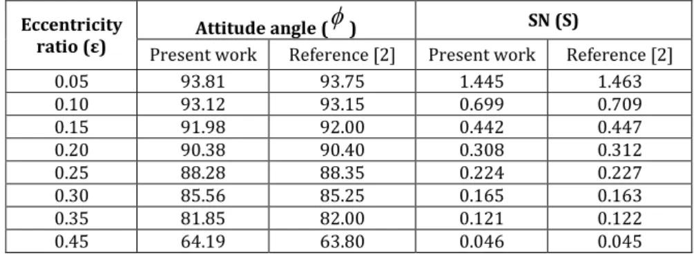
Table 2. For L/D=1, groove angle=20° and �=1 validation of theoretical model.
Eccentricity
ratio ε Attitude angle (
) SN (S)Present work Reference [2] Present work Reference [2]
0.05 93.81 93.75 1.445 1.463
0.10 93.12 93.15 0.699 0.709
0.15 91.98 92.00 0.442 0.447
0.20 90.38 90.40 0.308 0.312
0.25 88.28 88.35 0.224 0.227
0.30 85.56 85.25 0.165 0.163
0.35 81.85 82.00 0.121 0.122
0.45 64.19 63.80 0.046 0.045
Table 3. For L/D=1, groove angle=20° and �=1 validation of theoretical model.
Eccentricity
ratio ε Attitude angle (
) SN (S)Present work Reference [2] Present work Reference [2]
0.103 67.50 68.14 0.449 0.463
0.203 61.88 62.28 0.229 0.236
0.285 58.75 59.00 0.134 0.138
0.351 55.62 55.67 0.084 0.086
0.389 52.97 53.06 0.061 0.063
0.441 45.62 45.67 0.033 0.033
Table 4. For L/D=1, groove angle=20° and �=1 validation of theoretical model.
Eccentricity
ratio ε Attitude angle (
) SN (S)
Present work Reference [2] Present work Reference [2]
0.050 62.50 61.00 1.548 1.597
0.103 59.37 59.00 0.723 0.743
0.155 57.50 57.44 0.444 0.456
0.203 54.37 54.57 0.306 0.314
0.246 51.25 51.23 0.221 0.226
0.285 47.81 47.80 0.162 0.165
0.300 46.25 46.39 0.142 0.145
0.351 41.88 42.00 0.087 0.088
0.375 39.92 40.00 0.066 0.068
Fig. 2. Comparison of load capacity for isoviscous analysis.
Fig. 4. Comparison of flow coefficient for isoviscous analysis.
Load carrying capacity depends on the pressure developed inside the bearing. Lobe in the bearing creates oil wedge which increase the pressure. But for groove at the end of each lobe decrease the pressure to supply pressure near the groove. Bearing having more groove have less load carrying capacity. Since four-lobe bearing has four axial grooves, its load carrying capacity decreases because of less pressure developed inside the bearing. This is true only at low eccentricity, but at high eccentricity ratio load capacity of four-lobe bearing is high (Fig. 2). Friction variable found to be higher for two axial groove bearing and two lobe bearing. For three lobe bearing friction variable found to be lowest among the other three upto an eccentricity ratio 0.3 and above this eccentricity ratio friction variable found to be slightly higher than four-lobe bearing (Fig. 3). In case of two groove and two-lobe bearing greater flow attributed to large continuous film in the lower half or lobe which facilitates in increase in flow (Fig. 4).
3.2 Thermo-Hydrodynamic Analysis
In order to validate the THD results, the non-dimensional oil film temperature distribution obtained for single axial grooved journal bearing has been compared with experimental results listed in reference [14]. The bearing geometries, lubricant properties and operating parameter have been taken same as in reference [14]. In Fig. 5 the oil film temperature in non-dimensional form for experiment and present computational method has been compared. The temperature rise profile in the film has been found out in close agreement. The various Steady State Thermo-Viscous Characteristics for Two Axial Grooved Bearing at ε =0.45 and Λ=558 has been plotted. Film temperature distribution, Bush temperature in circumferential direction Shaft temperature variation along circumferential and axial direction is shown in Fig. 6. Comparison of
computed film temperature distribution of 2-lobe bearing with experimental data [5] is shown in Fig. 7. The various Steady State Thermo-Viscous Characteristics for Two Lobe Bearing at ε =0.45 and Λ=558. Film temperature distribution, Bush temperature and Shaft temperature variation is shown in Fig. 8.
Fig. 5. Comparison of computed film temperature distribution with experimental data [17] on the bearing centre plane.
Non-dimensional film pressure distribution for
ε=0.45, Λ=558, L/D=1, groove angle=20
Film temperature distribution in circumferential and axial direction
Shaft temperature variation near to the oil film along circumferential and axial direction Fig. 6. Film pressure, temperature distribution, Bush and Shaft temperature for two axial groove bearing.
Fig. 7. Comparison of computed film temperature distribution of 2-lobe bearing with experimental data [8] on the bearing centre plane.
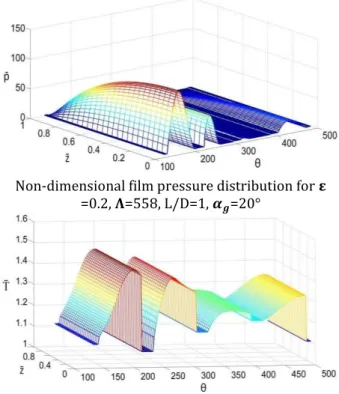
Non-dimensional film pressure distribution for � =0.2, �=558, L/D=1, ��=20°
Film temperature distribution in circumferential and axial direction
Bush temperature along the circumferential and
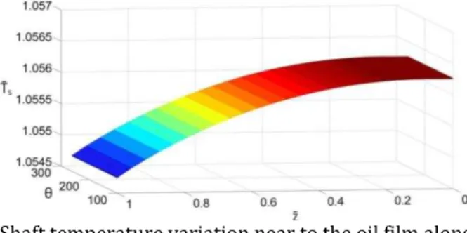
Shaft temperature variation near to the oil film along circumferential and axial direction
Fig. 8. Film pressure, temperature distribution, Bush and Shaft temperature for two-lobe bearing.
Non-dimensional film pressure distribution for � =0.2, �=558, L/D=1, ��=20°
Film temperature distribution in circumferential and axial direction
Bush temperature along circumferential and axial direction near to the oil film
Shaft temperature variation near to the oil film along circumferential and axial direction
Non-dimensional film pressure distribution for � =0.2, �=558, L/D=1, ��=20°
Film temperature distribution in circumferential and axial direction
Bush temperature along the circumferential and axial direction near to the oil film
Shaft temperature variation near to the oil film along circumferential and axial direction
Fig. 10. Film pressure, temperature distribution, Bush and Shaft temperature for four-lobe bearing.
The various Steady State Thermo-Viscous Characteristics for Three Lobe Bearing at ε=0.20 and Λ=558 is shown in Fig. 9. Pressure distribution, Film temperature distribution, Bush temperature and Shaft temperature variation is shown in Fig. 9. The various Steady
State Thermo-Viscous Characteristics for four Lobe Bearing at ε=0.20 and Λ=558 is shown Fig. 10. Pressure distribution, Film temperature distribution, Bush temperature and Shaft temperature variation is shown in Fig. 10.
4. EFFECT OF TEMPERATURE OVER PRESSURE DISTRIBUTION
In all the cases studied, the THD results provided a lower value of the peak pressure compared to that of isoviscous theory. It can be observed that pressure decreases due to reduction in the viscosity of lubricant film. This reduction in viscosity comes from the temperature rise by viscous shearing. This decrease in pressure profile causes to reduce the load carrying capacity of fluid film. Figure 11 shows the circumferential pressure distribution for 2-lobe bearing at the bearing mid-plane for THD and isoviscous theory.
Fig. 11. Pressure distribution for isoviscous and THD analysis at the bearing mid-plane for �=0.2, L/D=1 and � =558.
4.1 Lubricant Film Temperature Distribution
lubricating film. So here temperature rises with high slope. The location of maximum temperature in bearing occurs near to the minimum film thickness. After the minimum film thickness region again diverging portion comes in that THD solutions clearly reveal satisfactory feature of showing a drop in the oil temperature in the cavitation region.
4.2 Bush and Shaft Temperature Distribution
The temperature of bush material near to the minimum film thickness is much more than that of the other part. The groove region plays an important role in the heat transfer, because the lubricant comes at the supply temperature in the groove and this causes the heat flows from the bush material to the incoming lubricant where circumferential and axial temperature drops near to the groove region. The shaft temperature decreases along axial direction, means heat transfer takes place from the lateral face of the shaft to the surrounding. Circumferential temperature remains same due to the high speed of shaft rotation. Along the length of groove a slight decrease in shaft temperature is seen, incoming fluid at lower temperature comes and causes some heat transfer from the shaft to the fluid and consequently decreases the shaft temperature.
4.3Effect of Supply Pressure, Groove Size and Temperature-Viscosity Coefficient
Effect of input pressure to the bearing , groove size and temperature-viscosity coefficient for all model are studied. For two-lobe bearing with increase in supply pressure i.e. lowering bearing number, load carrying capacity decreases. With increase in groove angle ( ) load capacity decreases (Fig. 12), this is due to lower pressures in the smaller land region. Load capacity decreases with increase in temperature-viscosity coefficient, as viscosity decreases with increase in temperature-viscosity coefficient. A Comparison of non-dimensional load capacity, maximum pressure developed and maximum film temperature for two axial groove bearing, two-lobe, three-lobe and four-lobe bearing having 20° axial groove, ε=0.2, bearing number=558 and L/D=1 is shown. Pressure is developed due to formation of oil wedge in the clearance between the shaft and the bearing due
end of each lobe decrease the pressure to supply pressure near the groove.
Effect of supply pressure (� on load capacity W̄
Effect of groove angle ( on load capacity W̄
Effect of temperature-viscosity coefficient ( on
load capacity W̄
32.76
24.37
20.37
0 5 10 15 20 25 30 35
50000 67000 80000
Load
c
ap
ac
ity
Supply pressure (N/m2)
19 20 21 22 23 24 25
20 30 40
Load
c
ap
ac
ity
Groove angle (in degree)
21.5 22 22.5 23 23.5 24 24.5 25 25.5 26
0.03 0.034 0.04
Load
c
ap
ac
ity
Temperature-viscosity coefficient
0 5 10 15 20 25 30 35
Plain bearing
2-lobe bearing
3-lobe bearing
4-lobe bearing
Load
c
apac
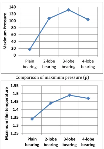
Comparison of maximum pressure p̄
Comparison of film temperature T̄
Fig. 12. Comparison of nom dimensional pressure, groove angle, temperature-viscosity coefficient on load capacity and comparison of load capacity, maximum pressure and film temperature for various bearing configuration.
Four-lobe bearing has four axial grooves, pressure developed inside the bearing is less due to low pressures in the short land region. Since load capacity of bearing depends on pressure developed by the shaft, therefore load capacity of four-lobe bearing is less. Film temperature depends upon the friction and friction depends on normal reaction force. So bearing having high load capacity will have more film temperature. Load capacity of three-lobe bearing is high as compared to two-lobe and four-lobe, hence its film temperature is also high.
5. CONCLUSIONS
A thermo-hydrodynamic model for the analysis of multi lobe bearings that allows the consideration of realistic oil supply conditions has been developed. Computational analysis of film pressure distribution, film temperature, bush temperature, shaft temperature, flow
coefficient, and friction variable have been carried out on a hydrodynamic axial grooved multi lobe bearing operating under steady state conditions. The results have been presented concerning the influence of shaft speed, L/D ratio, groove angle and supply pressure on the bearing performance characteristics. For the range of operating conditions studied, the following conclusions can be drawn:
1) Increase in lobe increases the number of oil wedge inside the bearing. This leads to a pressure buildup that creates a force normal to the surface. Lift force so created tends to force the surfaces apart.
2) The temperature excursions were significant along the circumference of the bearings, but not in the axial direction. The temperatures on the centre plane were slightly higher than towards the edges of the bearing.
3) The load carrying capacity increases with increase in eccentricity ratio for both isoviscous and thermoviscous cases and increase in load is more appreciable at high eccentricity ratio.
4) Results show that in each lobe the oil-bush interface temperature drops slightly in the vicinity of the inlet followed by a rapid rise in the circumferential direction and drop in the cavitation region.
5) Heat recirculates from the hottest point to the groove area in the fluid due to the convection,
6) With increasing oil supply pressure (lowering bearing number) load carrying capacity decreases.
7) The influence of shaft speed has also been investigated. Increasing shaft speed (increasing bearing number) has resulted in increasing load carrying capacity, oil temperature, bush temperature, shaft temperature and flow coefficient.
8) A bearing having smaller groove angle gives a higher load capacity, this is due to higher pressures in the larger land region.
9) As the flow coefficient for 2-lobe bearing shows an increase in magnitude with eccentricity, it appears that this bearing allows removal of heat more sufficiently than 3-lobe and 4-lobe bearing.
10)Comparing the isoviscous and THD analysis it can be concluded that THD
analysis presents more realistic operating characteristics for multi-lobe bearing.
11)At any eccentricity ratio the load-carrying capacity decreases with increase in the values of the thermal parameter, and a large reduction is obtained at higher values of eccentricity ratio.
12)The data obtained from the above analysis can be used conveniently in the design of such bearings, as these are presented in dimensionless form.
It is difficult to solve the thermal analysis of the axial grooved multi lobe bearing when operated with certain condition like high eccentricity ratio, due to numerically instabilities. Therefore further study can be carried out to solve the thermal analysis by using advance methods like adaptive meshing and multi-grid technique. However present study depicts that multi lobe bearing gives better performance in comparison to two axial grooved journal bearing.
NOMENCLATURE
Symbols Description
C Radial clearance (m)
ω Journal angular speed (rad/s) W Load carrying capacity of bearing or
applied load at the shaft
Attitude angle (degree) R Radius of journal (m)θ, ̄, z̄ Non-dimensional coordinates, θ=x/R,
ȳ=y/h, z̄=z/ L/2 , measured from the
top of bearing and at the mid-plane of groove
e, ε Eccentricity (m), eccentricity ratio
� = ⁄
θ Angular coordinate for bearing, measured from the maximum film thickness position
x, y, z Co-ordinate system for the bearing, x measures along circumference, z measures along the axis of rotation, y measures radial direction
h, h̄ Lubricant film thickness (m),
non-dimensional film thickness- ℎ̅ = ℎ⁄
, , Viscosity of lubricant film at the temperature of film, local average viscosity at local average temperature of lubricant film and viscosity of lubricant at supply temperature (Pa.s) T, Ts , TL, ̅ Lubricant film temperature at any
specified coordinates, supply
average temperature (oC), non-dimensional film temperature
̅ = ⁄
U Linear speed of moving surface (m/s) p, ps, p̄ Film pressure (Pa), supply pressure
(Pa) and non-dimensional film pressure �̅ = � �⁄
u, v, w Velocity components along the movement of surface, across the film and in axial direction (m/s)
Qx ,Qz Flow rate along circumferential and
axial direction (m3/s)
Cp Specific heat of lubricant (j/kgoC )
, Density of lubricant and density of lubricant at the supply conditions (kg/m3)
Tb , Tsh Temperature of bush and temperature
of shaft (oC)
� , �ℎ Radial coordinate for bush and shaft
O Center of bearing bush
Oʹ Center of shaft about which it rotates Tmix Mixing temperature of lubricating oil
h1 , h2 Film thickness at reformation and
cavitation boundary (m)
, Reformation and cavitation boundary (degree)
Q1 , Q2 , Qs Film inlet flow, recirculation flow and
supply flow (m3/s)
T1 , T2 , T0 Film inlet temperature, temperature
of recirculating fluid and temperature of incoming oil (oC)
Groove angle (degree) GL Groove length (m)
i, j , k Subscripts denote axial,
circumferential and radial directions L Length of bearing (m)
̄, v̄, w̄ Non-dimensional velocity components
ū=u/U, v̄=vR/CU and w̄=w/U
D Diameter of the bearing (m) N Journal rotation speed (rpm) Bib Biot number for bush =ℎ ��
Bis Biot number for shaft = ℎ
k Temperature rise parameter
� Bearing number, Λ = �
Inertial parameter = �
�= �
, , Non-dimensional parameters used in non-dimensionalized energy equation
Pe Peclet number
Rec Reynolds number for lubricating film
= �
F Friction force due to the viscosity of lubricant (N)
Assumed attitude angle (rad)
Wr , Wt Load components along line of centers
�̅ Non-dimensional load = � Coefficient of friction
̅ Friction variable = �
S
Sommerfeld number = �
� �
Rbi , Rbo, Rsh Inner bearing radius, outer bearing
radius and shaft radius (m) Kf Lubricant thermal conductivity
W/moC
Kb , Ks Thermal conductivity of bush and
shaft material (W/m oC)
hb ,, hs Convective heat transfer coefficient
for bush and shaft material (W/m2oC)
REFERENCES
[1] D. Clayton, M. Wilkie: Temperature Distribution in the Bush of a Journal Bearing, Eng., Vol. 166, p. 49, 1948.
[2] A. Cameron, W.L Wood: The Full Journal Bearing, Proceedings of the Institution of Mechanical Engineers, Vol. 161, pp. 59-64, 1949. [3] M.C. Shaw, E.F. Macks: Analysis and Lubrication
of Bearing, McGraw Hill Book Co, 1949.
[4] J. Cole: An Experimental Investigation of Temperature Effects In Journal Bearings, Proc. Convention on Lubr. And Wear, Inst. Mech. Engrs., London, Vol. 111, pp. 111-117, 1957. [5] M.T Ma, C.M. Taylor: An Experimental
Investigation of Thermal Effects in Circular and Elliptical Plain Journal Bearing, Tribology International, Vol. 29, No. 1, pp. 19-26, 1996. [6] E.R. Bowen, J.O. Medwell: A
Thermohydrodynamic Analysis of Journal Bearings Operating under Turbulent Conditions, Wear, Vol. 51, pp. 345-353, 1978.
[7] R.D. Flack, M.E. Leader, P.E. Allaire: An Experimental and Theoretical Investigation of Pressure in Four-Lobe Bearing, Wear, Vol. 61, pp. 233-242, 1980.
[8] J. Ferron, J. Frene, B. Boncompain: A Study of the Thermohydrodynamic Performance of a Plain Journal bearing Comparison Between Theory and Experiments, ASME, Vol. 105, pp 422-428, 1983.
[9] M.M. Khonsari: A Review of Thermal Effects in
(ydrodynamic Bearings, Part )): Journal Bearing”,
ASLE Trans., Vol. 30, No. 1, pp. 26-33, 1987.
[10] W.A. Crosby: A Thermohydrodynamic Solution of the-Two Lobe Bearing Considering Reverse Flow at the Leading and Trailing Edges, Wear, Vol. 143, pp. 159-173, 1991.
[11] S.S. Banwait, H.N. Chandrawat: Study of Thermal Boundary Conditions for a Plain Journal Bearing, Tribology International, Vol. 31, No. 6, pp. 289-96, 1998.
[12] L. Costa, M. Fillon, A.S. Miranda: An Experimental Investigation of the Effect of Groove Location and Supply Pressure on the THD Performance of a Steadily Loaded Journal Bearing, ASME, Vol. 122, pp. 227-32, 2000. [13] S.A. Gandjalikhan Nassab, M.S. Moayeri:
Three-Dimensional Thermodymanic Analysis of Axially Grooved Journal Bearings, Proc Instn Mech Engrs, Vol. 216, pp. 35-47, 2002.
[14] L. Costa, A.S. Miranda, M. Fillon, J.C.P. Claro: An Analysis of the Influence of Oil Supply Conditions on the Thermo hydrodynamic Performance of a Single-Grooved Journal Bearing, Proc Instn Mech Engrs, Vol. 217, pp. 133-44, 2003. [15] P. Karali: Estimation of Dynamic Coefficient and
Stability Analysis of Multi Lobe bearing, M-Tech Thesis Submitted to Deptt. of Mechanical Engineering, IIT-Guwahati, 2003.
[16] P.C. Mishra, R.K. Pandey,K. Athre: Temperature Profile of an Elliptic Bore Journal Bearing, Tribology International, Vol. 40, pp. 453-58, 2006. [17] A. Chauhan, R. Sehgal, R.K. Sharma:
Thermohydrodynamic Analysis of Elliptical Journal Bearing with Different Grade Oils, Tribology International, Vol. 43, pp. 1970-77, 2010.
[18] M. Akkok, C.M. Ettles: The Effect of Grooving and Bore Shape on the Stability of Journal Bearings, ASLE Trans., Vol. 23, No. 4, pp. 431-441, 1979.
[19] M. Akkok, C.M. Ettles: The Effect of Load and Feed Pressure on Oil Whirl of Grooved Journal Bearing, ASLE Trans., Vol. 22, No. 2, pp. 175-184, 1978.
![Table 1. For L/D=1, groove angle=20° and Λ=1 validation of theoretical model with reference [15]](https://thumb-eu.123doks.com/thumbv2/123dok_br/16516305.202366/5.892.92.435.100.399/table-groove-angle-λ-validation-theoretical-model-reference.webp)
![Fig. 5. Comparison of computed film temperature distribution with experimental data [17] on the bearing centre plane.](https://thumb-eu.123doks.com/thumbv2/123dok_br/16516305.202366/7.892.467.805.265.446/comparison-computed-temperature-distribution-experimental-bearing-centre-plane.webp)