N.B. Naduvinamani
Siddangouda A.
Gulbarga University Department of Mathematics 585 106 Gulbarga, India
Squeeze Film Lubrication Between
Circular Stepped Plates of Couple
Stress Fluids
In this paper, a theoretical analysis of the effects of couple stresses on the squeeze film lubrication between circular stepped plates is presented. Modified Reynolds type equation is derived for the couplestress fluids. Closed form solution is obtained. According to the results obtained, the influence of couple stresses enhances the squeeze film pressure, load carrying capacity, and decreases the response time as compared to classical Newtonian-lubricant case. The load carrying capacity decreases as step height increases.
Keywords: couple stresses, squeeze film, circular stepped plates
Introduction
1The squeeze film lubrication phenomenon is observed in several applications such as gears, bearings, machine tools, rolling elements and automotive engines. The squeeze film action is also seen during approach of faces of disc clutches under lubricated condition. The squeeze film phenomenon arises when the two lubricating surfaces move towards each other in the normal direction and generates a positive pressure, and hence supports a load. This is due to the fact that a viscous lubricant present between the two surfaces cannot be instantaneously squeezed out when the two surfaces move towards each other and this action provides a cushioning effect in bearings. The squeeze film lubrication between two infinitely long parallel plates is studied by Cameron (1981). The flow of an incompressible fluid between two parallel plates due to
normal motion of the plates is investigated by Bujurke et al.,(1995).
The unsteady flow between two parallel discs with arbitrary varying gap width was studied by Ishizawa (1966). The squeeze film with Newtonian lubricants has been studied by several investigators (Jackson, 1963; Burbidge and Colin, 2004; Gupta and Gupta, 1977). The Rayleigh step-bearings with non-Newtonian fluids have been studied by many researchers (Hughes, 1963; Bujurke et al., 1987; Maiti, 1973; Elkouh and Der-Fa, 1991).
The use of different liquids as lubricants under different circumstances has gained importance with the development of modern machines. In most of these lubricating oils the additives of high molecular weight polymers are present as a kind of viscosity index improvers. During the last few decades, the trend has been towards increasing of the viscosity index to manifolds, which is due to the fact that base oils with high viscosity index exhibit improved response to additives of various chemical composition which upgrade their quality and results in reduced additives consumption in the production of additive blended oils. Main advantages of the base oils of high viscosity index are highly reliable components of machine parts within a wide range of working temperature, a longer life and a good response to additives, etc. (Kragelsky and Alisin, 1981). The classical continuum mechanics of fluids neglect the size of fluid particles in the flow of fluids, and hence several microcontinuum theories have been proposed to take into account the intrinsic motion of material constituents (Ariman et al., 1973, 1974). The Stokes (1966) microcontinuum theory of couplestress fluid accounts for the polar effects such as the couple stresses, body couples and asymmetric tensor. During the last few decades Stokes microcontinuum theory has been extensively used to study the effect of couple stresses on the performance of various bearing systems
via: the slider bearings by Bujurke et al.(1990), Naduvinamani et al.
Paper accepted October, 2008. Technical Editor: Francisco R. Cunha.
(2003); journal bearings by Mak and Conway (1978), Guha (2004);
squeeze film bearings by Lin (1998), Naduvinamani et al. (2001)
and thrust bearings by Ramanaiah and Dubey (1975). These studies predicted the advantages of couplestress fluid lubricants over the Newtonian lubricants such as the increased load carrying capacity, decreased coefficient of friction in the slider bearings and delayed time of approach in squeeze film bearings.
So far no attempt has been made to study the squeeze film characteristics with couplestress lubricants between the circular stepped bearings. Hence, in this paper, an attempt has been made to analyze the effect of couple stresses on these bearings.
Nomenclature
i j
D deformation rate tensor
s
G the body couple
*
H non-dimensional mean film thickness 1
2 h h
⎛= ⎞ ⎜ ⎟ ⎝ ⎠.
1
h maximum film thickness
2
h minimum film thickness
* s
h step height
0
s h h
⎛= ⎞
⎜ ⎟
⎜ ⎟
⎝ ⎠
KR the position of the step 0< <K 1.
l couplestress parameter
( )
1 2
η µ
*
l non-dimensional couple stress parameter
2
2l h
⎛ ⎞ ⎜ ⎟ ⎝ ⎠
i j
M couplestress tensor
p pressure in the film region
p non-dimensional pressure 2R p
U
ε µ ⎛= ⎞ ⎜ ⎟ ⎜ ⎟ ⎝ ⎠
1
p fluid film pressure in the region 0≤ ≤r KR
2
p fluid film pressure in the region KR≤ ≤r R
Q volume flow rate.
R radius of the circular plate ,
r z radial and axial coordinates
,
r z non-dimensional radial and axial coordinates
(i j)
T symmetric part of Ti j
[i j]
T antisymmetric part of Ti j
t time of approach
*
t non-dimensional time of approach
2 0 3
8
W h t b L µ
V velocity of approach
V,Vivelocity vector
,
u w velocity components in rand z directions
,
u w non-dimensional form of u and w
W load carrying capacity
*
W non-dimensional load carrying capacity 23
3
2 3
W h R V
π µ
⎛ ⎞
⎜ ⎟
⎜ ⎟
⎝ ⎠
i j
W vorticity tensor
i
w vorticity vector
Greek Symbols
η lubricant couplestress constant
µ lubricant viscosity
i j
δ Kronecker delta
ρ density
ε small parameter h0
R
⎛= ⎞
⎜ ⎟
⎝ ⎠
ijs
ε alternating unit tensor
λ material constant having the dimension of viscosity
η′ material constant having the dimension of momentum
Superscripts
( )
− relative to nondimensional quantity( )
*relative to nondimensional quantity
Subscripts
1 relative to maximum film thickness 2 relative to minimum film thickness
s relative to film thickness
Mathematical Equations
A number of theories of the microcontinuum has been developed to explain the peculiar behavior of fluids containing substructure such as additives, suspensions or granular matter (Ariman et al., 1973; 1974). One class of fluids which has gained considerable attention in recent years is the couplestress fluid. Couple stresses are a consequence of the assumption that, the numeric action of one part of a body on another, across a surface, is equivalent to a force and moment distribution. Couplestress fluids consist of rigid randomly oriented particles suspended in a viscous medium such as blood, electro-rheological fluids and synthetic fluids. An important feature of couplestress fluid is that, the stress tensor is antisymmetric. The simplest microcontinuum theory generalizes the classical theory to allow for polar effects such as the presence of couplestress, body couples and asymmetric stress tensors (Stokes, 1966). The constitutive equations for force and couple stresses proposed by Stokes (1966) are
( )ij ( kk) ij 2 ij
T = − +P λ D δ + µD (1)
[ ] 2 ,
2
ij ij kk ijs s
T = − η W −ρ ε G (2)
and
, ,
4 4 ' ,
ij j i i j
M = η W + η W (3)
where
, ,
1
( ) ,
2
ij i j j i
D = V +V
, ,
1
( )
2
ij i j j i
W = − V −V
and
, 1
. 2
i ijk k j
w = ε V
Where T(i j) is the symmetric part and T[i j]is the antisymmetric
part of Ti j, Mi j the couplestress tensor, Di j the deformation rate
tensor, Wi j the vorticity tensor, Vi the velocity vector, wi the
vorticity vector , Gs the body couple, δi j the Kronecker delta, ρ
the density, p the pressure, εijs the alternating unit tensor, λ and µ
are the material constants having the dimension of viscosity
(namely, M LT), whereas η and η′ are the material constants
having the dimension of momentum (namely, ML T). The ratio
( )
ηµ has a dimension of length square, and we denote this material
constant by l, where
( )
1 2
l= ηµ .
The scheme of experiments for determining the material constants ,
µ η and 'η for incompressible fluids is given by Stokes (1966).
The basic equations governing the motion of incompressible steady couplestress fluids in the absence of body force and body moments are given by the following equations:
(
)
2 4,
ρ V⋅∇V= −∇ + ∇ − ∇P µ V η V (4)
0 V
∇ ⋅ = , (5)
where V is the velocity vector.
Analysis
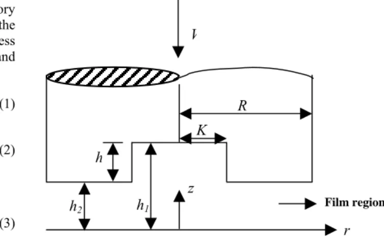
The squeeze film lubrication between circular stepped plates
approaching each other with a normal velocity V
(
dh)
dt
= is shown
in Fig. 1. The lubricant in the film region is considered to be an incompressible Stokes couplestress fluid, and the body forces and body couples are assumed to be absent.
Figure 1. Squeeze film between circular stepped plates.
h
2h
h
1z
r
V
K
R
The two dimensional field equations governing the motion of steady laminar couplestress fluid flow in the film region (in polar coordinates) are obtained from equations (4) and (5) as:
- Equations of motion:
2 2
2 2
2
2 2
2 2
1 1
1
u u p
u w u
r z r r r r z
u r r
r z
µ
ρ ρ
η ρ
⎡ ⎤
∂ + ∂ = − ∂ + ∂ + ∂ + ∂
⎢ ⎥
∂ ∂ ∂ ⎢⎣∂ ∂ ∂ ⎥⎦
⎡∂ ∂ ∂ ⎤
− ⎢∂ + ∂ +∂ ⎥
⎢ ⎥
⎣ ⎦ (6)
2 2
2 2
2
2 2
2 2
1 1
1
w w p
u w w
r z z r r r z
w r r
r z
µ
ρ ρ
η ρ
⎡ ⎤
∂ + ∂ = − ∂ + ⎢∂ + ∂ + ∂ ⎥
∂ ∂ ∂ ⎢⎣∂ ∂ ∂ ⎥⎦
⎡∂ ∂ ∂ ⎤
− ⎢∂ + ∂ +∂ ⎥
⎢ ⎥
⎣ ⎦ (7)
- Equation of continuity:
1
(ru) w 0
r r z
∂ +∂ =
∂ ∂ (8)
where u and w are the velocity components in the r and z direction
respectively.
Use of the following dimensionless scheme:
2 0
, , h , , ,
r z u w Rp
r z u w p
R R R U U U
ε ε
ε ε µ
= = = = = = .
in the equations (6), (7) and (8) gives
2 2
2 3 2
2 2
2
2 2
* 2
2 2
1
1
e e
e
u u p
u w R R u
r z r r r r z
R u
r r
r z
ε ε ε
ε
⎡ ⎛ ⎞ ⎤
∂ + ∂ = − ∂ + ⎢ ⎜∂ + ∂ ⎟+ ∂ ⎥
⎜ ⎟
∂ ∂ ∂ ⎢⎣ ⎝∂ ∂ ⎠ ∂ ⎥⎦
⎡ ⎛ ∂ ∂ ⎞ ∂ ⎤
− ⎢ ⎜⎜∂ + ∂ ⎟⎟+∂ ⎥
⎢ ⎝ ⎠ ⎥
⎣ ⎦
(9)
2 2
4 4 3 2
2 2
2
2 2
* 3 2
2 2
1
1
e e
e
w w p
u w R R w
r z z r r r z
R w
r r
r z
ε ε ε ε
ε ε
⎡ ⎛ ⎞ ⎤
∂ + ∂ = − ∂ + ⎢ ⎜∂ + ∂ ⎟+ ∂ ⎥
⎜ ⎟
∂ ∂ ∂ ⎢⎣ ⎝∂ ∂ ⎠ ∂ ⎥⎦
⎡ ⎛∂ ∂ ⎞ ∂ ⎤
− ⎢ ⎜⎜∂ + ∂ ⎟⎟+ ∂ ⎥
⎢ ⎝ ⎠ ⎥
⎣ ⎦
(10)
1
(ru) w 0
r r z
∂ +∂ =
∂ ∂ (11)
where Re
U
µ ρ
= and *
e
R U R
η ρ
=
Neglecting terms of order ε,ε2,ε3 and ε4 and retaining the terms
independent of ε (dominating terms), one can obtain the following
simplified equations of motion (in dimensional form):
2 4
2 4
u u p
r
z z
µ∂ −η∂ =∂∂
∂ ∂ (12)
0
p z
∂ =
∂ (13)
1
(ru) w 0
r r z
∂ +∂ =
∂ ∂ (14)
The relevant boundary conditions are:
i) At the upper surface z = h
0
u= 2
2 0
u y
∂ =
∂ (15a)
w= −V (15b)
ii) At the lower surface z = 0
0
u= 2
2 0
u y
∂ =
∂ (16a)
0
w= (16b)
The solution of equation (12) subject to the boundary conditions (15a) and (16a) is
2 2
2 cosh
1 2
2 1
2
cosh 2
z h
dp l
u z zh l
h dr
l µ
⎧ ⎡ ⎛ − ⎞⎤⎫ ⎪ ⎢ ⎜ ⎟⎥⎪ ⎪ ⎢ ⎝ ⎠⎥⎪ = ⎨ − + ⎢ − ⎛ ⎞ ⎥⎬ ⎪ ⎢ ⎜ ⎟ ⎥⎪ ⎪ ⎣ ⎝ ⎠ ⎦⎪
⎩ ⎭
(17)
where l η
µ
= is the couplestress parameter.
The volume flux of the lubricant is given by
0
2
h
Q= πr u dz
∫
(18)where 2πr is the circumference of the circle.
On using equation (17) in (18), we have
( , ) 6
r dp
Q s h l
dr
π µ
= − (19)
where ( , ) 3 12 2 24 3tanh
2
h
s h l h l h l
l
⎛ ⎞
= − + ⎜ ⎟
⎝ ⎠
Integration of the continuity equation (14) over the film thickness and the use of boundary conditions (15b) and (16b) gives
2
Q
r V
r π
∂ =
∂ (20)
Integration of equation (20) with respect to r and using the
condition 0Q= at r = 0 gives
2
Q=πV r (21)
The modified Reynolds type equation for determining the pressure is obtained from equations (19) and (21) in the form
6 ( , )
i
i i
dp V r
dr s h l
µ
where 1 1
2 2
, 0 ;
, .
i i
i i
p p h h for r KR
p p h h for KR r R
= = ≤ ≤
= = ≤ ≤
3 2 3
( , ) 12 24 tanh
2
i
i i i i
h
s h l h l h l
l
⎛ ⎞
= − + ⎜ ⎟
⎝ ⎠,
1
p and p2 being the pressure in the region-I
(
0≤ ≤r KR)
and inthe region-II
(
KR≤ ≤r R)
respectively.The relevant boundary conditions for the pressure are
1 2
p =p at r KR= (23a)
2 0
p = at r=R (23b)
The solution of equation (22) subject to the boundary conditions (23a) and (23b) is
2 2 2 2 2
1
1 1 2 2
(1 )
3
( , ) ( , )
K R r R K
p V
s h l s h l
µ ⎛ − − ⎞
= ⎜⎜ + ⎟⎟
⎝ ⎠ (24)
2 2 2 2 2 3 ( ) ( , ) V
p R r
s h l
µ
= − (25)
The load carrying capacity W is obtained in the form
1 2
0
2 2
KR R
KR
W = π
∫
r p dr + π∫
r p dr (26)which in non-dimensional form is
3 4 4
* 2
3 * * *
1 2
2 1
3 ( , ) (1 , )
W h K K
W
R V s H l s l
π µ
⎡ − ⎤
= =⎢ + ⎥
⎢ ⎥
⎣ ⎦ (27)
where * 1
2 h H
h
= and *
2
2l l
h
=
3 2 3 *
* * * * * *
1( , ) 3 3 tanh *
H
s H l H l H l
l ⎛ ⎞ = − + ⎜⎜ ⎟⎟ ⎝ ⎠ 2 3 * * * 2 * 1
(1 , ) 1 3 3 tanh
s l l l m
l
⎛ ⎞
= − + ⎜ ⎟
⎝ ⎠
Writing V dh2
dt
= − in equation (27), the squeezing time for
reducing the film thickness from an initial value h0 of h2 to a final
value hf is given by
0
4 4 4
2
1 1 2 2
3 1
2 ( , ) ( , )
f
h
h
R K K
t dh
W s h l s h l
µ π ⎛ − ⎞
= − ⎜⎜ + ⎟⎟
⎝ ⎠
∫
(28)which in non-dimensional form is
*
1 2
* 0 4 * * * * * *
1 2 2 2 2
3 { ( , , ) ( , ) }
8
f
s h
W h t
t K f h h l f h l dh
b L
µ ⎡ ⎤
= =
∫
⎣ ⎦+ (29)where
3 3 2 2 2
3
1 *
* * * * * * * *
2 2 2 2 *
2 *
* * * *
1 2 2 *
2 *
*
3 3 3 1
( , , ) 1
3 tanh
s
s s s
s s
h
h h h h h h l h
h
h
f h h l h
h l l − ⎡ + + + − ⎛ + ⎞ ⎤ ⎢ ⎜⎜ ⎟⎟ ⎥ ⎢ ⎝ ⎠ ⎥ ⎢ ⎛ ⎛ ⎞⎞⎥ ⎢ ⎥ =⎢ ⎜⎜ ⎜⎜ + ⎟⎟⎟⎟⎥ ⎝ ⎠ ⎢ + ⎜ ⎟⎥ ⎢ ⎜ ⎟⎥ ⎢ ⎜ ⎟⎥ ⎢ ⎝ ⎠⎥ ⎣ ⎦
3 2 3
4 * *
2 2 *
* * * * 2
2 2 *
1
( , )
3 3 tanh
K f h l
h
h l h l
l − = ⎛ ⎞ − + ⎜ ⎟⎜ ⎟ ⎝ ⎠ , * 0 , f f h h h
= * 2
2 0 , h h h = * 0 , s s h h h = * 0 2 . l l h =
Results and Discussion
This paper predicts the influence of couple stresses on the squeeze film characteristics of step bearings on the basis of Stokes couplestress fluid theory. The effect of couple stresses can be observed with the aid of nondimensional couplestress parameter
* 2 2l l h ⎛ ⎞ = ⎜ ⎟ ⎝ ⎠
, where l η
µ
= , which has the dimension of length and
this length can be identified as the chain length of the polar
additives in a non-polar lubricant. Hence, the parameter
l
*provides the mechanism of the interaction of the lubricant with the bearing geometry.
Load Carrying Capacity
The variation of nondimensional load carrying capacity W* as a
function of H* for different values of couple stress parameter l*
with K = 0.7 for circular stepped plates is as shown in Fig. 2. The
dashed curve in the graph corresponds to the Newtonian case. Compared with the Newtonian lubricant case, the effect of couple
stresses increase the load carrying capacity, and this increase in W*
is more accentuated for larger values of l*. An increase of nearly
41% in W*for circular stepped plates is observed in the present
study when l*=0.3 and K =0.7.
1 .0 1 .2 1 .4 1 .6 1 .8 2 .0 2 .2 2 .4 2 .6 2 .8 0 .8 1 .0 1 .2 1 .4 1 .6 W* H* l*
= 0 .0 [N e w to n ia n ] l*
= 0 .1 l*
= 0 .3 l*
= 0 .5
Figure 3 depicts the variation of nondimensional load carrying
capacity W* as a function of H* for different values of K for both
Newtonian lubricants (l*=0) and couplestress lubricants (l*=0.2).
It is observed that W*increases for decreasing value of K and this
increase in W*is more pronounced for larger values of H*.
1 .0 1 .2 1 .4 1 .6 1 .8 2 .0 2 .2 2 .4 2 .6 2 .8 0 .6
0 .7 0 .8 0 .9 1 .0 1 .1 1 .2
W*
H*
l*
= 0 .0 [N e w ton ian ] l*
= 0 .2 K = 0 .5 K = 0 .5 K = 0 .7 K = 0 .7 K = 0 .8 K = 0 .8
Figure 3. Variation of nondimensional load carrying capacity W* with H* for different values of K.
The relative percentage increase in W*,
*
W
R
(
)
* *
* 100
couplestress Newtonian Newtonian
W W
X W
⎛ ⎛ − ⎞ ⎞
⎜=⎜ ⎟ ⎟
⎜ ⎜ ⎟ ⎟
⎜ ⎝ ⎠ ⎟
⎝ ⎠
for different values of K ,
is given in Tab. 1.
Table 1. Variation of RW* and Rt* for different values of l* and K with H*=1.6
and h*f.
K l* RW* Rt*
0.1 2.748 5.072
0.3 23.112 42.941
0.5 0.5 62.916 117.721
0.1 2.655 4.879
0.3 22.335 41.298
0.7 0.5 60.789 113.177
0.1 2.533 4.663
0.3 21.313 39.450
0.8 0.5 57.987 108.064
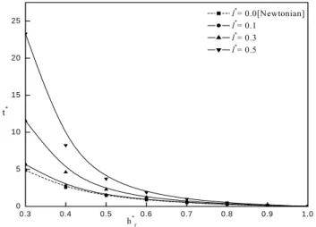
Time-Height Relationship
The most important characteristics of the squeeze film
bearings is the squeeze film time, i.e., the time required for
reducing the initial film thickness
h0of
h2to a final value
f
h
. Figure 4 shows the variation of the nondimensional time
of approach
*t
as a function of
* fh
for different values of
*l
with
K=0.5,
*0.15
s
h =
. It is observed that the presence of
couple stresses provides an increase in the response time
compared to the Newtonian
lubricant case. The relative increasein t*, Rt*
(
)
* *
* 100
couplestress Newtonian Newtonian
t t
X t
⎛ ⎛ − ⎞ ⎞
⎜=⎜ ⎟ ⎟
⎜ ⎜ ⎟ ⎟
⎜ ⎝ ⎠ ⎟
⎝ ⎠
is given in Table 1
for various values of l* and K. It is found an increase of nearly
20% in t*for l*=0.3 and K=0.7. The variation of t* with h*f
for different values of K for both Newtonian (l*=0) and
couplestress lubricants (l*=0.2) is depicted in the Fig. 5. It is
observed that t* increases for decreasing values of K. The variation
of t* with h*f for different values of step height
* s
h with K=0.6
is shown in Fig. 6. It is observed that t*decreases for increasing
values of non-dimensional step heighth*s.
0.3 0.4 0.5 0.6 0.7 0.8 0.9 1.0
0 5 10 15 20 25
t*
h*f
l*= 0.0[Newtonian] l*
= 0.1 l*
= 0.3 l*= 0.5
Figure 4. Variation of non-dimensional time of approach t* with h*f for
different values of l* with K=0.5, h*S= 0.15.
0 .3 0 .4 0 .5 0 .6 0 .7 0 .8 0 .9 1 .0
0 1 2 3 4 5 6 7 8 9
t*
h* f
l*
= 0 .0 [ N e w to n ia n ] l*
= 0 .2 K = 0 .3 K = 0 .3 K = 0 .5 K = 0 .5 K = 0 .7 K = 0 .7
Figure 5. Variation of non-dimensional time of approach t* with h*f for
0 .3 0 .4 0 .5 0 .6 0 .7 0 .8 0 .9 1 .0 0
1 2 3 4 5 6 7 8 9
t*
h*f
l*= 0 .0[N ew ton ian] l*= 0 .2 h*s= 0 .0 h*s= 0 .0 h*
s= 0 .15 h *
s= 0 .15
h*
s= 0 .2 h *
s= 0 .2
Figure 6. Variation of non-dimensional time of approach t* with h*f for
different values of h*Swith K = 0.5.
Conclusions
The squeeze film lubrication between circular stepped bearings with couplestress fluid as lubricant is studied on the basis of Stokes microcontinuum theory for couplestress fluids. On the basis of the theoretical results presented, the following conclusions are drawn:
1. The effect of couple stresses enhances the load carrying capacity significantly. This increase in load is 62% higher in comparison with the corresponding Newtonian case.
2. The relative increase in the load carrying capacity RW* is
found to be a function of K and l*.
3. The relative squeeze film time Rt* is found to be a function
of l* and K and Rt* increases for increasing values of *
l (as
high as 117%) and decreases for increasing values of K.
As it can be seen above, the theoretical results presented here suggest that the squeeze film characteristics between circular stepped plates can be improved by the use of lubricants with microstructure additives, which is in agreement with the experimental observations by Oliver (1988).
Acknowledgements
The authors are thankful to the reviewers for their valuable comments on the earlier draft of the paper. The authors sincerely acknowledge the financial assistance by the University Grants
Commission, New Delhi, India, under the major research project No.F.31-84/2005(SR).
References
Ariman, T., Turk, M. A., and Sylvester, N. D., 1973, “Microcontinuum fluid mechanics-a review”, International Journal of Engineering Science, Vol.11, pp.905-930.
Ariman, T., Turk, M. A., and Sylvester, N. D., 1974, “Application of microcontinuum fluid mechanics”, International Journal of Engineering Science, Vol.12, pp.273-287.
Bujurke, N. M., Achar, P. K., Pai, N. P., 1995, “Computer extended series for squeezing flow between plates”, Fluid Dynamics Research, Vol.16, pp.173-187.
Bujurke, N. M., Jagadeeshwar, M., and Mulimani, B. G., 1987, “Rayleigh step bearing with second-order fluid”, Japanese Journal of Applied Physics, Vol.26, No.12, pp.2121-2126.
Bujurke, N. M., Patil, H. P., and Bhavi, S. G., 1990, “Porous slider bearing with couple stress fluid”, Acta Mechanica, Vol.85, pp.99-113.
Burbidge, A. S., Colin Servais, 2004, “Squeeze flows of apparently lubricated thin films”, Journal of non-Newtonian Fluid Mechanics, Vol.124, pp.115-127.
Cameron, A., 1981, “Basic lubrication theory”, New York, Wiley. Elkouh, A. F., Der-Fa Yang, 1991, “Flow of power-law fluid in a Rayleigh step”, Transactions of the ASME, Vol.113, pp.428-433.
Guha, S. K., 2004, “A theoretical analysis of dynamic characteristics of finite hydrodynamic journal bearings lubricated with coupled stress fluids”, Journal of Engineering Tribology, Vol.218, pp.125-133.
Gupta, P. S., Gupta, A. S., 1977,“Squeezing flow between parallel plates”, Wear, Vol.45, No.2, pp.177.
Hughes, W. F., 1963, “The magnetohydrodynamic finite step slider bearing”, Journal of Basic Engineering, pp.129-136.
Ishizawa, S., 1966, “The unsteady flow between two parallel discs with arbitrary varying gap width”, Bulletin of JSME, Vol.35, pp.533-550.
Jackson, J. D.,1963, “A study of squeezing flow”, Applied Science Research Section A, Vol.11, pp.148-152.
Kragelsky, I.V. and Alisin, V.V., 1981, “Friction, Wear , Lubrication , Tribology Handbook”. Mir Publisher, Moscow.
Lin, J. R., 1998, “Squeeze film characteristics of finite journal bearings: couple stress fluid model”, Tribology Internatioal, Vol.31, No.4, pp.201-207.
Maiti, G., 1973,“Composite and step slider bearings in micropolar fluids”, Japanese Journal of Applied Physics. Vol.12, No.7, pp.1058-1064.
Mak, W. C., Conway, H.D., 1978, “Effects of velocity slip on the elastohydrodynamic lubrication of short porous journal bearings”, International Journal of Mechanical Science, Vol.20, pp.767-775.
Naduvinamani, N. B., Syeda Tasneem Fathima and Hiremath, P. S., 2003, “Hydrodynamic lubrication of rough slider bearings with couple stress fluids”, Tribology International, Vol.36, pp.949-959.
Naduvinamani, N.B., Hiremath, P.S., and Gurubasavaraj, G., 2001, “Squeeze film lubrication of a short porous journal bearing with couple stress fluids”, Tribology International , Vol.34, pp739-747.
Oliver. D.R., 1988, “Load enhancement effects due to polymer thickening in a short journal bearings”, Journal of non-Newtonian Fluid Mechanics, Vol. 30, pp.185-196.
Ramanaiah, G., Dubey, J.N., 1975, “Micropolar fluid lubricated squeeze films and thrust bearings”, Wear, Vol.32, pp.343-350.