NOVEL FRAGMENTATION MODEL FOR PULVERIZED
COAL PARTICLES GASIFICATION IN LOW TEMPERATURE
AIR THERMAL PLASMA
by
Rastko D. JOVANOVI]
*, Dejan B. CVETINOVI], Predrag Lj. STEFANOVI],
Predrag D. ŠKOBALJ, and Zoran J. MARKOVI]
Laboratory for Thermal Engineering and Energy, Vinca Institute of Nuclear Sciences, University of Belgrade, Belgrade, Serbia
Original scientific paper DOI: 10.2298/TSCI151222015J
New system for start-up and flame support based on coal gasification by low temperature air thermal plasma is planned to supplement current heavy oil sys-tem in Serbian thermal power plants in order to decrease air pollutions emission and operational costs. Locally introduced plasma thermal energy heats up and ignites entrained coal particles, thus starting chain process which releases heat energy from gasified coal particles inside burner channel. Important stages dur-ing particle combustion, such as particle devolatilisation and char combustion, are described with satisfying accuracy in existing commercial computer fluid dy-namics codes that are extensively used as powerful tool for pulverized coal com-bustion and gasification modeling. However, during plasma coal gasification, high plasma temperature induces strong thermal stresses inside interacting coal particles. These stresses lead to “thermal shock” and extensive particle fragmen-tation during which coal particles with initial size of 50-100 µm disintegrate into fragments of at most 5-10 µm. This intensifies volatile release by a factor 3-4 and substantially accelerates the oxidation of combustible matter. Particle fragmenta-tion, due to its small size and thus limited influence on combustion process is commonly neglected in modelling. The main focus of this work is to suggest novel approach to pulverized coal gasification under high temperature conditions and to implement it into commercial comprehensive code ANSYS FLUENT 14.0. Pro-posed model was validated against experimental data obtained in newly built pi-lot scale direct current plasma burner test facility. Newly developed model showed very good agreement with experimental results with relative error less than 10%, while the standard built-in gasification model had error up to 25%. Key words: Serbian lignite gasification, low temperature thermal plasma, CFD,
particle fragmentation, modeling validation
Introduction
Primary energy production in Serbia includes the exploitation and use of domestic resources of coal, crude-oil, natural gas, and renewable energy (hydropower, geothermal en-ergy, biodiesel, and fuel wood). In 2010, Serbia has produced 10539 Mtoe of primary enen-ergy, which supplies about 65% of the total energy consumption. The production of coal is domi-nant, which makes 68% of the total domestic primary production, while the rest are related to hydro potential, oil production, fuel wood, and natural gas. Coal is mostly low quality lignite ––––––––––––––
from open pit mines which is dominantly (80% of total consumption) used for power genera-tion in thermal power plants. In the structure of final energy consumpgenera-tion by sector, most en-ergy was consumed in the household sector with 35%, industry 27%, and transport 25%, while all other sectors accounted for 13%. Serbian thermal power plants consume 55000 tons of heavy oil for boilers start up and for pulverized lignite combustion support and stabilization which correspond to almost 0.8% of coal energy consumption for power generation [1].
However, the quality of Serbian lignite coals is declining. The ash and moisture content are increasing while coal volatile content is decreasing. Moreover, significant fluctuations exist in different coal portions used during boiler operation. These phenomena lead to poor flame igni-tion, flame instability, and low temperature level in the furnace. It is necessary to use additional thermal energy input in order to ensure stable combustion process under described conditions.
Existing oil burner system in Thermal power plant “Nikola Tesla”, Obrenovac, Ser-bia, is planned to be supplemented with a new system for combustion support based on pul-verized coal thermo-chemical treatment by low temperature air thermal plasma. In this tech-nology hot air plasma produced in plasma generators is introduced into pulverized coal-air mixture duct. The plasma flame with high thermal energy concentration induces coal gasifica-tion and partial char oxidagasifica-tion, thus producing highly reactive mixture of combustible gases and partially oxidized char particles. This highly combustible mixture is easily ignited at the furnace entry ensuring high flame stability and overall increased combustion efficiency.
The main advantages of novel low temperature thermal plasma system are the fol-lowing: it can be easily implemented in the existing boiler units, eliminates/reduces need for heavy oil start-up/flame support, enables reliable coal flame stabilization, and decreases NOx
and unburnt carbon emissions which is very promising for future implementation in energy technology mitigation measures [2].
In order to fully implement proposed plasma system to full scale boilers it is neces-sary to demonstrate its advantages over conventional systems for boiler start-up and flame support. However, full-scale studies on industrial boilers are very costly, time consuming, and sometimes even unfeasible. Because of this CFD simulation was chosen as already proven tool for pulverized coal chemical processes modeling [3, 4].
Significant efforts in the field of CFD modeling of coal plasma gasification are re-ported in the number of studies. Jankoski [5] numerically simulated the process of pulverized coal chemical treatment for combustion using plasmas. Temperature profiles, coal particles history and major species concentrations at the plasma burner exit were presented and dis-cussed in his work.
Gorokhovski et al. [6] reported results of 1-D and 3-D CFD simulations of plasma aided coal combustion with analysis of involved chemical kinetic and fluid dynamics.
Askarova et al. [7] conducted mathematical modeling in order to investigate igni-tion/combustion behavior of plasma activated pulverized coal particles. They performed both 1-D and 3-D simulations. Species concentrations, velocities, and temperatures of treated pul-verized coal-air mixture were obtained as results of one-dimensional simulation. These data were used as initial step for 3-D CFD simulation, which enabled a comprehensive image of plasma activated coal combustion process in a furnace of a pulverized coal fired boiler.
The main scope of work
tem-perature conditions, i. e. at furnace temperatures in the range of 1300-2000 K. On the other hand, pulverized coal plasma gasification involves phenomena which either do not exist or do not have important role in the common pulverized coal firing, and thus are not accounted for in pulverized coal gasification/ignition CFD models. The most important are: very high tem-peratures (2000-5000 K) and present large variations in physical properties, the electromag-netic field in the plasma, and thermal shock caused by high temperature gradients present in the plasma affected region.
The subject of this paper is 3-D numerical modeling of plasma supported pulver-ized-coal gasification inside pulverized coal-air burner ducts. The aim of this paper is to sug-gest novel numerical model suitable for modeling of a transport and thermo-chemical pro-cesses occurring during coal gasification with low temperature air plasma. Detailed model de-scription will be given in next sections. Model accuracy was verified against experimental da-ta obda-tained from the pilot scale plasma burner built in the Laboratory for Thermal Engineer-ing and Energy, Vinca Institute of Nuclear Sciences, Belgrade, Serbia. Experimental stand and procedure are also described in this work. After its accuracy was established, model was applied to the real scale industrial boiler pulverized coal-air mixture channels in order to es-tablish the most favorable conditions for plasma treatment.
Mathematical model
Although many authors write their own home codes which offer high flexibility in implementing many equations and specificities of the considered problem they have difficul-ties when dealing with real geometries which often require complicated numerical grids. Since reactive flow field investigated in this work is highly 3-D and thus has to be solved on complex 3-D mesh, authors have decided to use commercial CFD solver ANSYS FLUENT 14.0 together with ANSYS GAMBIT 2.3.0 grid generator which can easily handle 3-D geom-etries. Moreover, FLUENT 14.0 offers user to implement its own subroutines written in C programming language. Using these subroutines one can implement transport equations for special cases like thermal plasma coal combustion support. In this way it was possible to ad-just original FLUENT code for thermal plasma gasification modeling.
The reactive flow field was described in Eulerian manner solving Reynolds aver-aged Navier-Stokes (RANS) transport equations for mass, momentum, energy, and reacting species mass fractions. The pulverized coal particles combustion is modeled in a Lagrangian reference frame. Particles trajectories were computed solving the particle momentum equation through the calculated gas field with momentum, mass, and heat transfer between the gas phase and the combusting particles. This transfer between the two phases appears as source/sink terms in the flow field governing equations and was set to occur at every 35 flow iterations. The particle temperature inside reactor was calculated taking into account the heat transfers due to convection, radiation and the heat generated by the char reactions. The turbu-lence was modeled using the standard k-ε turbulence model together with standard wall func-tions. Radiative heat transfer was modeled using discrete ordinates (DO) model. The gas radi-ation absorption coefficient is calculated as function of characteristic cell-size and gas con-centrations [8].
Burning coal particle undergoes the following phenomena during its combus-tion/gasification: inert heating, devolatilisation, and char combustion. The coal particles initial density ρ = 1000 kg/m3, thermal heat capacity, cp = 1100 J/kgK, and heat conductivity,
λ = 0,1 W/mK. Single rate temperature dependent devolatilisation model expressed in
factor A = 3.82·105 1/s and the activation energy E = 7.4·107 J/kmol, which are found to be satisfactory for Serbian lignite coals from Kolubara basin were adopted accord-ing to Jovanović et al. [9]. Although coal volatile matter is composed of several dif-ferent gaseous, the released volatile matter was represented by a single virtual hydro-carbon CxHyOz, where x, y, and z are
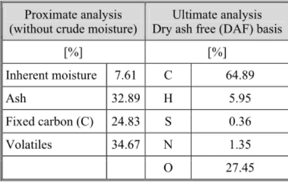
gov-erned by the pre-dried coal ultimate and proximate analysis shown in tab. 1.
The reaction rates between the re-leased gaseous species and the surrounding oxidant are limited either by the turbulent mixing rate of the evolved gas species and oxidizer or by the chemical kinetic rate. The finite rate/eddy dissipation model, which takes into ac-count both phenomena, with the following reaction paths was employed for the gaseous reac-tions modeling:
2 2
2 2
2 2
2 2 2
y
C H O O xCO+ H (a)
2 2 2
1
CO + O CO (b)
2
1
CO CO + O (c)
2 1
H O H O (d)
2
x y z
x z ⎛ ⎞ +⎜ − ⎟ → ⎝ ⎠ → → + → (1)
Chemical kinetic rates for gaseous reactions are expressed by an Arrhenius equation kg = Ag Tbexp(–Eg/RT). The necessary Arrhenius parameters are given in tab. 2.
Table 2. Kinetic rate data of the involved gaseous reactions
A simplified multi-surface reaction mechanism with three global char oxidation re-actions was used to model influence of char combustion/gasification process:
2
2 2
2
2C(s) O 2CO (a)
C(s) H O CO H (b)
C(s) CO 2CO (c)
+ →
+ → +
+ →
(2)
Table 1. Typical Serbian lignite pre-dried coal (from Kolubara basin) proximate and ultimate analysis
Proximate analysis (without crude moisture)
Ultimate analysis Dry ash free (DAF) basis
[%] [%]
Inherent moisture 7.61 C 64.89
Ash 32.89 H 5.95
Fixed carbon (C) 24.83 S 0.36
Volatiles 34.67 N 1.35
O 27.45
Reaction [kmolm–3s–1]
Ag (units vary)
Eg [Jkmol–1]
b [–]
Species
concentration Reference
(1a) 4.4·1011 1.25·108 0 [CxHyOz]0.5[O2]1.25 [10]
(1b) 2.239·1012 1.702·108 0 [CO][O2]0.25[H2O]0,5
[11]
(1c) 5.0·108 1.702·108 0 [CO2]
The overall char consum-ption rate is the summation of these individual surface reaction rates. It was assumed that char reaction rate for each of reac-tions (2a)-(2c) is governed by the slower of the two processes: chemical kinetics or diffusion
of gaseous reactants to the char external surface. The kinetic rate constants of the char reac-tions are defined in Arrhenius form kP = APTPb·exp[EP/(RTP)]. Diffusion limited reaction rate
constant is expressed as kd = C [(TP+ Tg)/2]0.75/dP. The kinetics parameters and overall
diffu-sion-limited coefficients are presented in tab. 3. Particle temperature exponent, b, is equal ze-ro for all char reactions.
Existing fragmentation sub-models in CFD codes
As to the authors knowledge there were very few publications about integration of fragmentation sub-models into CFD codes. Syred et al., [14] implemented simplified percola-tion model of Mitchell and Akanetuk [15] into FLUENT CFD code. Although their model was successfully tested in number of applications it has major obstacles which prevent its use for plasma activated pulverized coal gasification modeling. Namely, their model assumes that fragmentation occurs only during char combustion phase. While this assumption is applicable for common pulverized fuel combustion conditions it was already explained that during plas-ma aided pulverized coal gasification due to high temperature gradients entrained particles undergo thermal shock and can fragment as early as during devolatilisation phase. Moreover, the above mentioned model is purely statistical, assuming that fragmentation starts when 10% of char is consumed and stays in effect till the end of process independently of any physical conditions. In order to implement fragmentation subroutine authors had to rewrite whole combustion model as set of user defined functions. This is due to particle density and diame-ter not being defined independently in the default combustion subroutine incorporated in FLUENT, therefore, it was necessary to intervene in the way FLUENT calculates density. Otherwise, unrealistic increase of particle density is inevitable following dramatic particle size reduction caused by fragmentation [14].
Recently, Kreutzkam et al., [16] developed fragmentation subroutine which can be used together with standard FLUENT’s combustion model. With an implemented user-defined function, particles which fragment are removed from the calculation. With the remov-al, particle variables like position, temperature or velocity for every single tracked particle are stored in a global matrix to be applied to the new injected fragments. For the input of the gen-erated fragments, additional injections have been defined. In the second step, the function loops over all particles and injects three to five new particles at the point, where a single par-ticle stopped in the first step. In this approach the parpar-ticle density is calculated directly by FLUENT solver from the diameter and mass of the new particle.
Although, Kreutzkam et al., [16] model does not require rewriting of FLUENT de-fault combustion model it has serious limitation. Since new particles are injected after every fragmentation step tremendous computing resources may be necessary in order to track all fragmented particles. In their work authors injected 25000 particles at the beginning of calcu-lation procedure, ending with 120000 tracked particles, assuming that each particle fragments only once during its lifetime.
Table 3. Char reaction parameters
Reaction AP
[kgm–2s–1Pa–1] EP [Jkmol–1]
C
[sK–0,75] Reference
(2a) 0.005 7.4·107 5.32·10–12 [12]
(2b) 0.00192 1.47·108 5.77·10–12
[13]
Fragmentation sub-model development and implementation
Due to shortcomings of described fragmentation sub-models authors of this work decided to propose their own fragmentation subroutine which aims to fulfill two main re-quirements:
– proposed subroutine does not require significant increase in computational resources in compare with standard FLUENT combustion model, and
– proposed subroutine is based on physical conditions rather than on statistical theories for particle fragmentation.
In the Lagrangian approach physical properties (position, velocity, diameter, densi-ty, mass, and temperature) of individual particles are tracked with time. It would be ideal to track all individual particles however, due to limited computational resources, this is
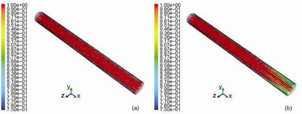
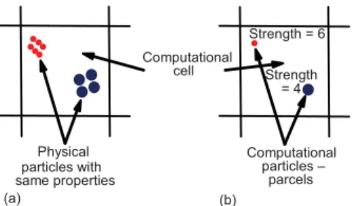
practi-cally impossible. Thus, a smaller number of computational particles are chosen to represent actual physical particles. In this way one compu-tational particle, often termed parcel, contains a number of physical particles with same proper-ties. As example, two different groups of physi-cal particles are shown in fig. 1(a). Particles in each group share same physical features (no overlapping particles are shown for visualization purposes only). These physical particles will be represented by only two computational parcels (one for each group physical particles) in order to save computational resources, fig. 1(b). In or-der to take into account number of physical particles in a single parcel additional variable termed strength is applied to each parcel. Strength is defined inside FLUENT solver as parcel mass flow rate divided by single particle mass and essentially represents number of physical particles in a parcel per second.
According to the experimental research conducted by Messerle and Ustimenko [17] coal particles undergo thermal shock and fragment if particle heating rate is higher than 103-104 ºC/s. In the same work authors investigated fragmentation behavior of low quality coals concluding that coal particles under thermal plasma influence with average diameter up to 100 µm produce 5-10 fragments, while bigger particles (with average diameter up to 250 µm) may give 8-10 fragments. These criteria, in a simplified form that covers both parti-cle diameter ranges, were incorporated in the fragmentation model as a starting approach:
3
P Pold
10
T
T
t
−
≥
∆
(3)Pold P
8
m
m
=
(4)where ∆t is the particle integration time step, TP and TPold are particle temperature values at
the beginning and at the end of particle integration time step, respectively, and mP and mPold
are particle mass values at the beginning and at the end of particle integration time step, re-spectively. Particle time step is calculated based on characteristic cell size in which particle is currently positioned divided by particle velocity.
Figure 1. Computational representation of physical particles
Computational cell
Computational particles –
parcels Physical
particles with same properties
Strength = 6
Strength = 4
The main challenge in fragmentation subroutine development came from the fact that density and diameter are not calculated independently in the default FLUENT combus-tion routine, namely particle mass loss is calculated only with a reduccombus-tion of density, but not diameter. In order to overcome this limitation, it was necessary to alter the way FLUENT cal-culates particle density.
Assuming that particle density does not change due to fragmentation, eq. (4) be-comes:
Pold
P 1/ 3
8 d
d = (5)
where dP and dPold are particle diameters at the beginning and at the end of particle time step,
respectively.
Condition (3) is checked at the start of calculation and every time that particle posi-tion is updated (i. e. at the beginning of every particle time step). If this condition is met FLUENT solver executes user defined fragmentation model. Particle diameter is changed ac-cording to eq. (5), while particle mass is updated acac-cording to eq. (4). Particle density is than calculated based on obtained values for particle mass and particle diameter. In order to ac-count for number of newly created particles it is necessary to change number of particles in-side parcel by modifying parcel strength.
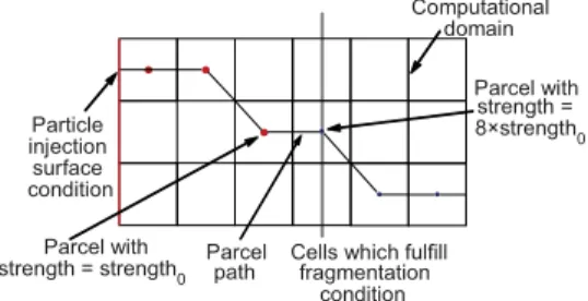
This is performed by employing external function which modifies initial parcel mass at entry into domain. Since parcel mass flow remains same, parcel strength is increased for the number of newly created fragments. Function then searches for fragmentation po-sition on parcel path and applies modified value for parcel strength at that point on-wards, fig. 2.
Implementation of the fragmentation subroutine into FLUENT code required re-writing significant part of default combustion model. Particle laws for inert heating,
devolatilisation and char combustion together with all surface reactions were written as user defined functions and attached to the main FLUENT solver. This was very complicated pro-cedure due to large number of interconnected fluid and particle variables. Developed user de-fined combustion model without fragmentation was compared with standard FLUENT com-bustion model in order to ensure that these quantities were properly incorporated and that there is no significant difference between two models.
Model evaluation
Fragmentation of inert particles was implemented in the first phase of model devel-opment. Particles were tracked through cylindrical channel with inner diameter d = 0.32 m and length l = 3.54 m which are identical to experimental plasma burner channel dimensions shown in the following chapter. Particles were injected from channel inlet surface with mass flow rate m = 0.252 kg/s. Inlet gas mass flow and gas temperature were set to minlet = 0.8 kg/s and T = 1273 K, thus giving particle concentration and residence time equal to those in exper-imental plasma burner channel. Fragmentation condition (3) was neglected at this phase of
Figure 2. Schematically shown fragmentation subroutine to be implemented in suitable algorithm Particle injection surface condition Computational domain
Cells which fulfill fragmentation condition Parcel path Parcel with strength = strength0
Parcel with strength = 8×strength0
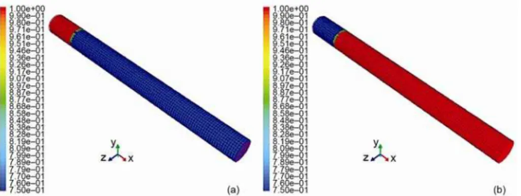
development and instead it was assumed that all particles fragment at 0,4 m from inlet surface (position at which plasma is introduced into experimental burner). The obtained results in terms of particle mass, diameter, and strength change are shown in figs. 3.
Figure 3. Results of inert particles fragmentation modeling in cylindrical channel; particle tracks: (a) colored by particle mass [kg], (b) colored by particle strength [number of particles s–1]
Coal particles devolatilisation modeling was included in the next phase of numerical simulation, while gaseous and char reactions were not incorpo-rated at this stage. The main goal was to show fragmentation process influence on total volatile re-lease dependence on pulverized coal particle size. It can be seen from fig. 4 that if total mass flow rate of injected particles is kept constant, volatile release rapidly decreases with particle size increase.
This can be explained by the fact that overall external area of entrained particles (through which volatiles are released) decreases with particle size increase. Thus, the amount of released volatiles is the biggest in the case of the smallest (dP = 90 µm)
particles, around 64.3% of initial volatile content. This amount drops to about only 1.68% in the case of big, 2 mm particles. On the other hand, fig. 4 clearly shows importance of proper fragmentation phenomenon modeling which becomes more im-portant with particle size increase. Total volatile release increases for only 6% when novel fragmentation model is included in case of 90 µm, while this value increases up to 200% and 400% for 1 mm and 2 mm particles, respectively (fig. 5).
Full combustion model with devolatilisation, fragmentation, volatile and char com-bustion reactions was implemented using set of five different user defined functions in the last stage of model evaluation. Model was tested using the same geometry and for the same oper-ating conditions as in previous development step.
It can be seen that volatile release is much higher than in a previous test case. Com-plete devolatilisation is predicted in case of both 90 µm and 200 µm particles even without
Figure 5. Results of pulverized coal particles devolatilisation modeling in cylindrical channel (no combustion modeling); particle tracks colored by particle volatile mass fraction [kgvolkgvol0–1]; (a) particle diameter d = 1000 µm, (b) d = 2000 µm
fragmentation model included. If fragmentation is considered complete devolatilisation is achieved also in case of 500 µm, while in case of 1 mm particles about 70% of initially psent volatiles is released, fig. 6. This enhanced devolatilisation is caused by additional heat re-leased as a product of involved combustion reaction mechanisms, reactions (1) and (2). Char burnout is presented in fig. 7.
Figure 6. Results of pulverized coal particles combustion modeling in cylindrical channel; dependence of total volatile release on particle size
Figure 7. Results of pulverized coal particles combustion modeling in cylindrical channel; dependence of burnt char mass fraction on particle size
Figure 8. Results of pulverized coal particles combustion modeling in cylindrical channel; particle tracks colored by particle char mass fraction [kgcharlkgchar0–1]; particle diameter d = 90 µm; (a) without fragmentation modeling, (b) with fragmentation modeling
Figure 9. Results of pulverized coal particles combustion modeling in cylindrical channel; particle tracks colored by particle char mass fraction [kgcharlkgchar0–1]; particle diameter d = 200 µm; (a) without fragmentation modeling, (b) with fragmentation modeling
Model assessment
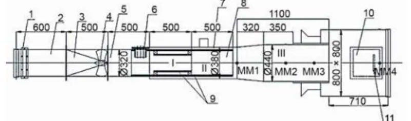
Developed fragmentation model was applied for numerical simulation of pulverized coal gasification inside experimental plasma burner channel pilot facility built in the Labora-tory for Thermal Engineering and Energy, Vinca Institute of Nuclear Sciences, Belgrade, Ser-bia. The main elements of experimental test facility are shown in fig. 11.
Figure 11. Schematic presentation of experimental plasma coal burner pilot facility
Pulverized coal particles are introduced into channel (2) using screw feeder (1). Swirl generator (3) ensures homogeneous mixing of pulverized coal particles and primary air. Plasma generator (6) is mounted on air burner channel (5) which is divided into 3 stages (I, II, and III). The first section of burner channel (5 I) is divided into two thermally insulated (9) coaxial parts. One third of total air-coal mixture stream is introduced through the inner section and ignited by low temperature thermal plasma. The bigger portion of pulverized coal mixture is introduced through outer section and subsequently mixed with and ignited by the already burning inner stream at the beginning of the second channel stage (5 II). Secondary air can be introduced separately of primary stream using additional air fan. Gasification process contin-ues by mixing swirled secondary and primary streams inside third part of burner channel (5 III). Quartz glass window (10) enables visual monitoring of coal gasification process. Various sampling probes can be inserted using openings (MM1, MM2, MM3, and MM4) on channel walls. The main operating
parameters of laboratory stand and their values used in gasification exper-iment presented in this study are given in tab. 4.
Temperature measure-ments during gasification experiment were perfor-med using special multi-channel thermal probes based on high sensitivity K-type thermocouples.
The net measurements consisting of eight thermal probes each (four along horizontal and four along vertical cross-section axis) were mounted at four different channel cross-sections (fig. 11, MM1, MM2, MM3, and MM4).
The four different computational grids: coarse (consisting of 22752 elements), me-dium (consisting of 33970 elements), fine (consisting of 46880 elements), and very fine (con-sisting of 59651 elements) were created in order to conduct grid independency tests. Medium
Table 4. Experimental plasma burner operating conditions
Parameter Operating range Experiment
Primary air mass flow rate 0-2 kg/s 0.8 kg/s
Secondary air mass flow rate 0.2-0.3 kg/s not used at this stage
Plasma mass flow rate 0.01-0.2 kg/s 0.15 kg/s
Plasma generator power input 60-150 kW 100 kW
Primary air temperature 300 K 300 K
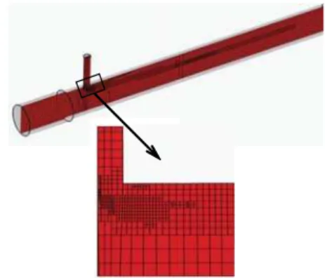
mesh was created decreasing average cell size for about 30% compared with coarse grid. Fine grid was created based on temperature gradient obtained from reactive flow field calculated on coarse grid in a way that each computational cell in high temperature gradient zone was di-vided in four new computational cells, fig. 12. The same procedure was followed for very fine mesh using temperature gradient calculated on fine grid. Since maximal difference in average gas temperature in chosen cross-sections dropped to 2% between fine and very-fine grids it was decided to select fine mesh to validate numerical results with the experimental data from pilot scale plasma burner.
Gas temperature contours in vertical cross-sections at distances z = 1.92 m, 2.46 m, and 3 m from burner inlet surface for cases with default built-in FLUENT combustion model and user written combustion model with novel fragmenta-tion sub-routine are presented in fig. 13.
High temperature region, with tempera-tures about 2000 K is located in thin layer near upper burner wall when gasification is modeled without fragmentation. In this case gas tempera-ture rapidly drops to about 900 K at the end of 1/3 of channel height. It can be clearly seen that size of the high temperature plasma affected zone increases with use of fragmentation. The highest temperature values of about 2000 K are now located near central part of channel upper wall section in circular shaped zone. Tempera-ture slowly drops away from this zone in the contrast with rapid temperature drop present in the previous case. High temperature zone is spread in about 2/3 of channel cross-section. This enlarged high temperature zone favors pul-verized coal gasification, enhancing volatile release and volatile and char oxidation.
Conclusions drawn from temperature profiles are further confirmed by comparing released volatile and CO mass fractions values between standard and user developed combus-tion models. Volatile mass fraccombus-tion in bulk gas for default and user implemented combuscombus-tion models are shown in fig. 14. Maximal volatile mass fraction (about 5%) is located in very small zone just below location at which plasma stream is introduced into burner channel de-fault combustion is used. Zone with maximal volatile yield in bulk gas (about 5%) is much bigger when coal gasification is modeled together with particle fragmentation. This zone elongates to the half of channel length. In both cases volatile fraction decreases downstream from plasma generator position due to involved volatile combustion reactions. Average vola-tile mass fractions at cross-sections z = const. is two times higher when fragmentation is
mod-Figure 12. Adopted computational mesh used for CFD simulations with detailed view
eled in compare with simulations performed without particle fragmentation. Fragmentation in-fluence is most clearly expressed in CO mass fraction distribution. Maximal CO mass fraction is about 6% and 22.5% for default and user modified combustion models, respectively. This difference in CO mass fraction values between two models is result of coal particle conver-sion processes. Namely, fragmentation enhances devolatilisation. Released volatiles burn to CO and release the heat. Released heat increases gas temperature which intensifies char gasi-fication process which results with additional CO and heat.
Figure 14. Comparisons between default combustion model and combustion model with included fragmentation modeling; released volatile mass fraction [kgvolkggas–1] and CO mass fraction [kgCOkggas–1] distribution at central channel plane y = 0 m
Comparison between experimentally measured and numerically obtained (for de-fault and user developed combustion models) temperature values is shown in fig. 15.
Temperature drop along channel axis at distances x/D > 2 originates from heat losses through channel walls. Numerical results ob-tained using standard FLUENT combustion model which does not take fragmentation into account predicts gas temperatures with satis-fying accuracy. This somewhat unexpected agreement between simulation and experi-mental results can be explained by the fact that very fine coal particles with 75% particles having diameter smaller than 500 µm were utilized during gasification trial. Average
rela-tive difference between experimentally and numerically obtained values is in range 20%-25% in this case. Significantly better agreement between measured and numerically obtained re-sults was achieved using user modified combustion model with fragmentation routine. Rela-tive error in this case drops to about 10% which is satisfactory for its application.
Conclusions
Pulverized coal combustion models used in majority of commercially available CFD codes do not include fragmentation phenomena under general assumption that it does not play significant role in the process. Of course, this assumption remains valid for a number of ap-plication and offered combustion models satisfactory represent real physical situation.
Pulverized coal gasification by low temperature air D. C. thermal plasma involves locally high temperature gradients which cause thermal shock and rapid fragmentation of en-trained coal particles that may dramatically enhance devolatilisation process and char burnout.
In order to represent described phenomena novel fragmentation sub-routine was proposed and embedded in FLUENT general purpose CFD solver.
The proposed fragmentation model is based on physical condition for particle frag-mentation unlike few already developed fragfrag-mentation models that can be find in the litera-ture which have statistical nalitera-ture.
Model implementation proved as very challenging task since it involved rewriting of complete FUENT particle combustion model using set of user defined functions written in C programming language. However, developed model does not require any increase in computa-tional resources during calculation when compared with standard combustion model. This was accomplished by altering number of particles in parcel rather than increasing number of tracked parcels.
Model was developed using step by step procedure starting from modeling of the fragmentation of inert particles at the beginning to modeling of the fragmentation of combust-ing particles includcombust-ing models for devolatilisation, volatile, and char combustion.
At the final stage model was validated against experimental data obtained from ex-perimental plasma burner channel built in the Laboratory for Thermal Engineering and Ener-gy, Vinca Institute of Nuclear Sciences, Belgrade, Serbia.
Presented results clearly pointed out importance of fragmentation process on overall pulverized coal gasification process using low temperature air thermal plasma.
Fragmentation influence is smaller than it may be expected mainly due to small par-ticle sizes used during gasification experiment. However, based on presented model evalua-tion for particles with different sizes, it is expected that fragmentaevalua-tion modeling will play sig-nificant role in plasma gasification modeling inside real scale burner channels due to bigger particles which exist in full scale burner channels.
Acknowledgments
The authors would like to express their appreciation for the efforts of the Ministry of Education, Science and Technological Development of the Republic of Serbia in supporting and promoting this work through scientific projects referenced III42010 and TR33050.
Nomenclature
A – pre-exponential factor (units vary) b – temperature exponent, [–]
C – mass diffusion limited rate constant, [sK–0,75] cp – specific heat capacity, [Jkg–1K–1]
d – diameter, [m]
E – activation energy, [Jkmol–1]
k – kinetic or diffusion rate, [kgm–2s–1Pa–1] l – length, [m]
m – mass, [kg]
m – mass flow rate, [kgs–1]
R – gas constant (= 8,314), [Jkmol–1K–1] T – temperature, [K]
∆t – discrete phase (particle) integration time step, [s]
z – longitudinal Cartesian co-ordinate, [m] Greek symbols
λ – heat conductivity, [Wm–1K–1]
ρ – density, [kgm–3] Subscripts
d – diffusion g – gaseous phase
inlet – inlet into computational domain old – value from previous iteration P – particle
0 – initial stage 1 – final stage
References
[2] Cvetinović, D., et al., Ghg (Greenhouse Gases) Emission Inventory and Mitigation Measures for Public District Heating Plants in the Republic of Serbia, Energy, 57 (2013), Aug., pp. 788-795
[3] Jovanović, R., et al., Turbulent Two‐Phase Flow Modeling of Air‐Coal Mixture Channels with Single Blade Turbulators, American Institute of Physics, Proceedings, Aip Conference, Vol. 936, 2007, pp. 300-303
[4] Williams, A., et al., Modelling Coal Combustion: The Current Position, Fuel, 81 (2002), 5, pp. 605-618 [5] Jankoski, Z., Improvement of Coal Combustion Efficiency and Decrease of Harmful Emission under the
Influence of Plasma – Modelling, Proceedings, 31st EPS Conference on Plasma Phys., Vol. 28g, p. 4063, London, 2004
[6] Gorokhovski, M. A., et al., Enhancement of Pulverized Coal Combustion by Plasma Technology,
Com-bustion Science and Technology, 179 (2007), 10, pp. 2065-2090
[7] Askarova, A. S., et al., Plasma-Supported Coal Combustion in Boiler Furnace, Transactions on Plasma
Science, 35 (2007), 6, pp. 1607-1616
[8] ***, ANSYS, Inc. ANSYS FLUENT 14.0 Theory Guide Release 13.0; 2011
[9] Jovanović, R., et al., Sensitivity Analysis of Different Kinetic Factors for Numerical Modeling of Serbi-an Lignite Devolatilization Process, International Journal of Heat and Mass Transfer, 72 (2014), May, pp. 489-500
[10]Jones, W. P., Lindstedt, R. P., Global Reaction Schemes for Hydrocarbon Combustion, Combustion and
Flames, 73 (1988), 3, pp. 233-249
[11]Westbrook, C. K., Dryer, F. L., Simplified Reaction-Mechanisms for the Oxidation of Hydrocarbon Fuels in Flames, Combustion Science and Technology, 27 (1981), 1-2, pp. 31-43
[12]Field, M., Rate of Combustion of Size-Graded Fractions of Char from a Low-Rank Coal between 1200 K and 2000 K, Combustion and Flame, 13 (1969), 3, pp. 237-252
[13]Smoot, D., Pratt, D., Pulverised-Coal Combustion and Gasification Theory and Applications for
Contin-uous Flow Processes, Plenum Press, New York, USA, 1979
[14]Syred, N., et al., Development of Fragmentation Models for Solid Fuel Combustion and Gasification as Subroutines for Inclusion in CFD Codes, Fuel, 86 (2007), 14, pp. 2221-2231
[15]Mitchell, R., Akanetuk, A., The Impact of Fragmentation on Char Combustion during Pulverized Coal Combustion, Symposium International on Combustion, 26 (1996), 2, pp. 3137-3144
[16]Kreutzkam, B., et al., Improved Numerical Prediction of Ash Formation and Deposition Using a Novel Developed Char Fragmentation Model, Fuel, 98 (2012), Aug., pp. 103-110
[17]Messerle, V. E., Ustimenko, A. B., Solid Fuel Plasma Gasification, Advanced Combustion and Aerothermal Technologies, Springer, Dordrecht, The Netherlands, 2007, pp 141-156
![Figure 5. Results of pulverized coal particles devolatilisation modeling in cylindrical channel (no combustion modeling); particle tracks colored by particle volatile mass fraction [kg vol kg vol0 –1 ];](https://thumb-eu.123doks.com/thumbv2/123dok_br/16396635.193166/9.918.198.728.219.433/pulverized-particles-devolatilisation-cylindrical-combustion-particle-particle-fraction.webp)