Numerical Simulation and Structural
Optimization of the Inclined Oil/Water
Separator
Liqiong Chen1☯, Shijuan Wu1, Hongfang Lu1
*, Kun Huang1☯, Lijie Zhao2
1School of Petroleum Engineering, Southwest Petroleum University, Chengdu, Sichuan, China,2College of Geosciences, State Key Laboratory of Petroleum Resources and Prospecting, China University of Petroleum, Beijing, China
☯These authors contributed equally to this work. *[email protected]
Abstract
Improving the separation efficiency of the inclined oil/water separator, a new type of gravity separation equipment, is of great importance. In order to obtain a comprehensive under-standing of the internal flow field of the separation process of oil and water within this sepa-rator, a numerical simulation based on Euler multiphase flow analysis and the realizablek-ε two equation turbulence model was executed using Fluent software. The optimal value ranges of the separator’s various structural parameters used in the numerical simulation were selected through orthogonal array experiments. A field experiment on the separator was conducted with optimized structural parameters in order to validate the reliability of the numerical simulation results. The research results indicated that the horizontal position of the dispenser, the hole number, and the diameter had significant effects on the oil/water separation efficiency, and that the longitudinal position of the dispenser and the position of the weir plate had insignificant effects on the oil/water separation efficiency. The optimal structural parameters obtained through the orthogonal array experiments resulted in an oil/ water separation efficiency of up to 95%, which was 4.996% greater than that realized by the original structural parameters.
Introduction
The changes in crude oil components and operating conditions resulting from oilfield develop-ment have created problems with oilfield production and crude oil gathering, transportation, and storage. The inability of conventional oil/water separators to adapt to today’s high water content is a major issue that could be effectively solved by converting horizontal separators into inclined separators and, thereby, improving separation efficiency.
In 2006, relevant studies were performed on the inclined free water separator in China’s Daqing Oilfield. Indoor simulations and field experiments were conducted, resulting in the development of aF2.0 × 20 m inclined separator, which was applied in 2009 [1].
OPEN ACCESS
Citation:Chen L, Wu S, Lu H, Huang K, Zhao L (2015) Numerical Simulation and Structural Optimization of the Inclined Oil/Water Separator. PLoS ONE 10(4): e0124095. doi:10.1371/journal. pone.0124095
Academic Editor:Xiao-Dong Wang, North China Electric Power University, CHINA
Received:December 16, 2014
Accepted:February 25, 2015
Published:April 13, 2015
Copyright:© 2015 Chen et al. This is an open access article distributed under the terms of the
Creative Commons Attribution License, which permits unrestricted use, distribution, and reproduction in any medium, provided the original author and source are credited.
Data Availability Statement:All relevant data are within the paper and its Supporting Information files.
Funding:This research is supported by Science and Technology Innovation Foundation of CNPC (2012D-5006-0602) and Graduate Innovation Foundation of SouthWest Petroleum University (SGIFSWPU). The funders had no role in study design, data collection and analysis, decision to publish, or preparation of the manuscript.
In 2008, the Southwest Petroleum University proposed a design concept for an inclined-plate, gas-liquid separator. Studies have shown that this separator has a simple structure, good separation effects, and a short separation time [2].
Researchers have conducted a plethora of studies on the inclined oil/water separator. How-ever, due to the large number of factors that influence oil/water separation and the diversity of separator structures, a comprehensive set of design theories and methods has not been devel-oped. The design of the inclined oil/water separator, according to empirical data alone, often cannot achieve the best separation effects. Therefore, in order to improve the efficiency of oil/ water separation, comprehensive studies on the internal flow field of inclined oil/water separa-tors and the motion of oil droplets are necessary [3–5].
In recent years, an increasing number of scholars have applied computational fluid dynam-ics (CFD) to studies on oil/water separation and have used CFD software to optimize the struc-ture of oil/water separation equipment [6,7]. He Limin from the China University of
Petroleum used the volume of fluid (VOF) model to study the oil/water two-phase flow and ob-tained the critical particle size range for separation equipment [8,9]. Hou Xianrui from Dalian Maritime University used the Mixture model to simulate the effects of the inlet component, the baffle, and the coalescing component on the separation performance of gravity oil/water sepa-ration equipment [10]. Zhang Li from Tianjin University used the Laminar model to simulate the effects of the inlet component and baffle on the separation performance of gravity oil/water separation equipment and optimized the structure of oil/water separation equipment based on the simulation results [11].
In this study, a mathematical model was created based on basic inclined separator theory. Fluent software was used to execute a numerical simulation of an inclined separator. Based on the simulation results, an orthogonal array of experiments was performed in order to optimize the structure of the inclined separator, and a field experiment was executed in order to validate the separation efficiency of the optimized separator.
Basic Theory
Separation Principle
The inclined oil/water separator is an oil/water separation device that uses the buoyancy sepa-ration method; the sepasepa-ration principle of this separator is shown inFig 1. After a large volume of liquid enters the device, the oil phase gathers in the upper portion of the separator, and the water phase gathers in the lower portion of the separator. Next, gravity separation occurs in the oil phase gathering section, and buoyancy separation occurs in the water phase gathering sec-tion. Because the water phase comprises the majority of the liquid, buoyancy separation is the primary separation process of the produced liquid [1].
Main components
The inclined oil/water separator primarily consists of the separation tank, dispenser, oil outlet, water outlet, oil weir, and water weir; its schematic diagram is shown inFig 2.
Currently, most separator dispensers are uniformly distributed round holes with equal diameters.
The weir plates are mostly used to regulate the oil/water interface within the separation tank. The horizontal positions of the oil and water weirs in the oil/water separator often range between 0.5 D and 1.5 m, where D is the diameter of the separator.
Separation efficiency
The separation performance of an oil/water separator is often represented with the separation efficiency,, which is defined as
¼1 Cd
Ci 1
whereCdis the water outlet oil content;Ciis the inlet oil content.
Mathematical Model
Based on Euler multiphase flow analysis, the realizablek-two equation turbulence models
was used to perform a numerical simulation of the oil and water separation process of an in-clined separator. This necessitated a mathematical model [12,13].
Fig 1. The separation principle of the inclined oil/water separator.
doi:10.1371/journal.pone.0124095.g001
Fig 2. The schematic diagram of the inclined oil/water separator.
The flow control equations for oil and water separation are the continuity and momentum equations. The universal control equation for turbulent incompressible fluids is
@ðrFÞ
@t þ rðruFÞ ¼ rðGgradðFÞÞ þS 2
whereρis thefluid density, kg/m3);Fis a universal variable that can represent velocity and
temperature;uis the velocity vector, m/s);Γis the generalized diffusion coefficient;Sis a
gen-eralized source term.
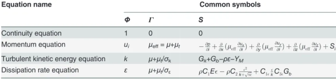
The relationships of the continuity, momentum, turbulent kinetic energy, and dissipation rate equations with common symbols are shown inTable 1.
Case Study
Basic data for the separator
The handling capacity of the inclined separator analyzed in this study was 300 m3/d, with a res-idence time of 6 min and an oil content of 10%. The diameter of the mixture inlet was 70 mm, the diameter of the water outlet was 50 mm, and the diameter of the oil outlet was 50 mm [13]. The concrete geometrical dimensions of the established model are shown inTable 2.
Inlet boundary conditions
The inlet was defined as the velocity inlet. The flow velocity at the inlet was 0.9 m/s (based on the actual conditions, the corresponding volume flow rate was 300.00 m3/d), and the velocity at the inlet was assumed to be uniformly distributed. The turbulent intensity at the inlet was 4.49%. The hydraulic diameter was 70.00 mm.
Table 1. The concrete forms of the symbols in the universal control equations for turbulence.
Equation name Common symbols
Φ Γ S
Continuity equation 1 0 0
Momentum equation ui μeff=μ+μt @@piþ
@ @xðmeff
@ux @iÞ þ
@ @yðmeff
@uy @iÞ þ
@ @zðmeff
@uz @iÞ þSi
Turbulent kinetic energy equation k μ+μt/σk Gk+Gb−ρε−YM
Dissipation rate equation ε μ+μt/σε rC1E rC2 2
kþpffiffiffinþC1
kC3Gb
wherei=x,y,z;μeffis the effective viscosity, Pa·s;μis the dynamic viscosity, Pa·s;μtis the turbulent
viscosity, Pa·s;ux,uy,uzare the velocity components in thex,y, andzdirections, m/s;pis thefluid
pressure, Pa;Sx,Sy,Szare the source terms, which have different expressions under different conditions;k
is the turbulent kinetic energy per unit mass, m2/s2;σkis the Prandtl number for turbulent kinetic energy,
dimensionless, whose value is 1.0;Gkis the production term for turbulent kinetic energy caused by the
average velocity gradient, N/ (m2·s);Gbis the production term for turbulent kinetic energy due to buoyancy,
N/ (m2·s);εis the rate of dissipation of turbulent kinetic energy per unit mass, m2/s3;YMis the dilatation
dissipation, kg/ (m·s3);σεis the turbulent Prandtl number for dissipation rate, dimensionless, whose value is
1.2;C1is a dimensionless constant;Eis the time-average strain rate, s-1;νis the coefficient of molecular dynamic viscosity, m2/s;C1ε,C3ε,C2are empirical constants, dimensionless, with values ofC1ε= 1.44,
Outlet boundary conditions
The free outflow boundary condition was applied at the outlet. Volume flow rate fraction at oil outlet is 10%, and volume flow rate fraction at water outlet is 90%.
Wall boundary conditions
The no-slip boundary condition was used on the wall of the separator; thus, the wall was static. The fluid and turbulent velocities on the wall were equal to zero. The wall toughness was set as 0.15 mm.
Meshing of the model
The structure of the inclined oil/water separator simulation model was large and complex, and adaptive meshing was adopted in Gambit. In order to ensure the precision and adaptability of the meshing, the mesh density was set to 2.5 mm × 2.5 mm. The entire computational domain consisted of 483,612 cells, and the dispenser mesh consisted of 5,149 cells.
Physical parameters
The medium used for the purposes of this simulation consisted of a mixture of water and crude oil; the water content was 90%. The density and dynamic viscosity of water are 1000 kg/m3and 1 mPa·s, respectively, and the density and dynamic viscosity of crude oil are 870 kg/m3and 51 mPa·s, respectively.
Numerical Simulation Results
Separation efficiency
In order to study the separation performance of the inclined oil/water separator, numerical simulations were conducted at varying inclinations, ranging from 0° to 30°. Statistics regarding the water volume content at the oil outlet, the oil volume content at the water outlet, and the oil/water separation efficiency of the model at varying inclinations are shown inS1 Table.
According toS1 Table, when the inclination ranged from 0° to 12°, the oil/water separation efficiency increased as the inclination increased; when the inclination ranged from 15° to 25°, the oil/water separation efficiency decreased as the inclination increased; and when the Table 2. The geometrical dimensions of the model.
Basic parameters Dimension Basic parameters Dimension
Length of the separation tank (m) 7.78 Diameter of the liquid inlet (m) 0.07
Diameter of the separation tank (m) 0.44 Length of the oil outlet (m) 0.1
Volume of the separation tank (m3) 1.18 Diameter of the water outlet (m) 0.05
Length of the dispenser (m) 0.7 Length of the water outlet (m) 0.1
Diameter of the dispenser (m) 0.07 Height of the oil weir (m) 0.8D
Hole number of the dispenser 7 Position of the oil weir (m) 1.0D
Hole diameter of the dispenser 0.02 Height of the water weir (m) 0.5D
Hole spacing 3.0d Position of the water weir (m) 1.0D
Longitudinal position of the dispenser 0.5D Long radius of the head (m) 0.22
Horizontal (x) position of the dispenser 75%Le Short radius of the head (m) 0.11
Note: D represents the diameter of the separator body; d represents the hole diameter of the dispenser; and Lerepresents the length of the major
separation region of the separator, namely the distance between the weirs.
inclination was greater than 25°, the oil/water separation efficiency decreased significantly as the inclination increased.
Oil and water volume phase distributions
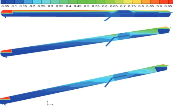
Through numerical simulations, the distributions of oil and water in the separator were ob-tained. The volume distributions of oil in the axial sections for some of the calculation models are shown inFig 3.
As shown inFig 3, the two phases near the separator dispenser mixed vigorously, and the isoline of the oil/water interface exhibited obvious bends. In addition, as the inclination in-creased, the“dead oil”and“dead water”within the separator reduced gradually; the inclined oil/water separator exhibited a significant reduction in“dead oil”and“dead water”compared to the conventional horizontal oil/water separator. Furthermore, as the inclination increased, the separator’s oil/water interface fluctuated greatly; when the inclination increased to 18°, the oil/water interface fluctuated considerably, and“swirling flow”occurred in the upper region. The fluctuations in the oil/water interface could cause the separated oil and water phases at the interface to mix.
Droplet trajectories
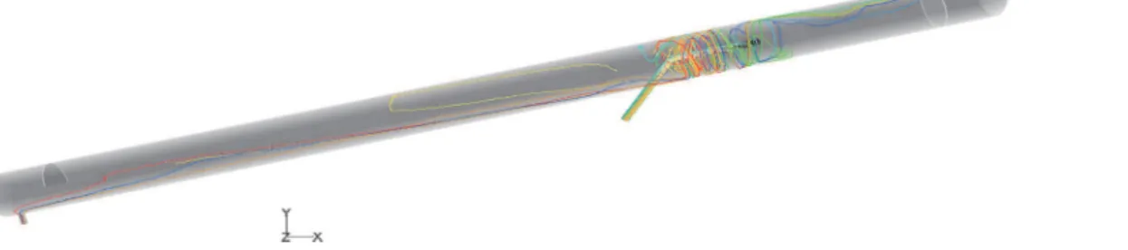
The effect of flow fields on droplet motion depends on the trajectories of those droplets. The droplet trajectories within the oil/water separator at an inclination of 12° were obtained through numerical simulations, as shown inFig 4. In addition, a separator with a length/diam-eter ratio of 10 was simulated in order to study the effect of the length/diamlength/diam-eter ratio on droplet trajectories, as shown inFig 5.
According toFig 4andFig 5, when the length/diameter ratio was equal to 10, some of the oil droplets that entered the separator were not separated, and the swirling flow structure of the liquid droplets at the dispenser was complex. When the length/diameter ratio was equal to 15, only a small portion of the oil droplets that entered the separator were not separated, and the Fig 3. Oil and water volume distributions at different inclinations.(A) Inclination = 0°; (B) Inclination = 12° and (C) Inclination = 18°.
separation effect was satisfactory. Thus, a separator with a length/diameter ratio of 15 and a 12° inclination could meet the requirements and obtain a desired oil/water separation effect.
Velocity field distribution
The velocity vectors within the inclined oil/water separator are shown inFig 6.
According toFig 6, after flowing through the dispenser, the oil and water phases sprayed onto the lower wall of the dispenser at high rates. After the impact, swirls were generated be-tween the dispenser and the wall of the separation tank so that the oil and water phases passed through the dispenser region at high speeds. Mild swirls were also generated after collision with the weir.
Structural Optimization
A large number of structural parameters affect the separation performance of an inclined oil/ water separator, and any structural change could affect the efficiency of the separator. In order to prevent complicated experiments and improve efficiency without compromising applicabili-ty, orthogonal array experiments were used to study the effects of the main structural parame-ters on the oil/water separation efficiency. Through horizontal comparison, the optimal structural parameters for the inclined oil/water separator were obtained.
Orthogonal array experiments
(1) Influencing factors and their levels. An inclined oil/water separator primarily consists of the separation tank, dispenser, oil outlet, water outlet, oil weir, and water weir. In this study, the effects of eleven factors, including the weir height, weir position, hole diameter and spacing of the dispenser, horizontal and longitudinal positions of the dispenser, and the structure of the oil outlet, on separation efficiency were analyzed, and an orthogonal array at five levels, whose factors and levels are shown inS2 Table, was designed [14–16].
Fig 4. The droplet trajectories within a separator with a length/diameter ratio of 15.
doi:10.1371/journal.pone.0124095.g004
Fig 5. The droplet trajectories within a separator with a length/diameter ratio of 10.
This experimental design consisted of eleven factors with five levels for each factor. There could be 511experimental conditions for a comprehensive experimental design; however, this would be impractical. Thus, aL50(511) orthogonal array was selected, which consisted of fifty
simulations (S3 Table).
(2) Analysis of the results. Fifty simulations were performed for eleven factors at five els. The averages and ranges of the separation efficiencies for the various factors at different lev-els are shown inS4 Table.
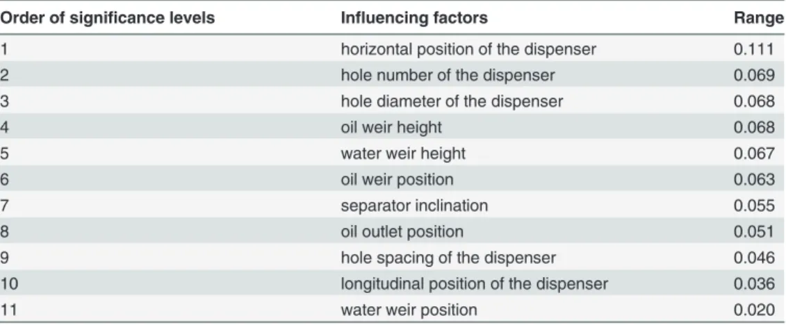
The significance of the various structural parameters on the oil/water separation efficiency was determined through a range analysis of the numerical simulation results. A large range in-dicated that the oil/water separation efficiencies for a certain factor at different levels were sig-nificantly different and that the factor had a significant effect on the oil/water separation efficiency. A small range indicated that this factor had a small effect on the oil/water separation efficiency. The significance levels of the various factors on the oil/water separation efficiency in descending order are shown inTable 3. (Note: The higher the significance level number, the less important the corresponding influencing factor is.)
According toTable 3, the horizontal position, hole number, and hole diameter of the dis-penser had significant effects on the oil/water separation efficiency; the longitudinal position of the dispenser and the position of the water weir had insignificant effects on the oil/water sepa-ration efficiency; and the other factors had effects that fell between those extremities.
(3) Effects of the structural parameters on separation efficiency. The changes in the fac-tor levels had significant effects on the oil/water separation efficiency; the study of these effects Fig 6. The velocity vectors for a 12° inclination.
doi:10.1371/journal.pone.0124095.g006
Table 3. Range analysis.
Order of significance levels Influencing factors Range
1 horizontal position of the dispenser 0.111
2 hole number of the dispenser 0.069
3 hole diameter of the dispenser 0.068
4 oil weir height 0.068
5 water weir height 0.067
6 oil weir position 0.063
7 separator inclination 0.055
8 oil outlet position 0.051
9 hole spacing of the dispenser 0.046
10 longitudinal position of the dispenser 0.036
11 water weir position 0.020
is of great importance in separator optimization. Numerical simulations were performed under various conditions, such as different inclination and oil weir parameters; only one variable was used in each simulation. For example, in the analysis of the effect of inclination on separation efficiency, the inclination alone was changed. The obtained optimal parameter values are shown inS5 Table(Note: X represent separation efficiency).
Structural optimization
In order to obtain the optimal structural parameters of the inclined oil/water separator, the fac-tor levels that demonstrated the highest separation efficiencies were combined with the struc-tural parameters that demonstrated the highest separation efficiencies, as shown inFig 7. The results are shown inTable 4.
The model with the optimal structural parameters obtained through computational analysis was not included in the orthogonal array of fifty experiments. Since the fifty simulations com-prised only a fraction of the comprehensive experiments, a validation experiment was neces-sary to analyze other possible optimal structural parameters and examine the reproducibility of the optimal structural parameters. In addition, the results had to be compared to the results of the fifty simulations in order to determine the quality of the optimal structural parameters ob-tained through computational analysis.
A numerical simulation was executed for the inclined oil/water separator shown in
Table 4under the same conditions mentioned above. The result was compared to the first three
simulation results obtained through range analysis in order to determine the optimal structural parameters of the inclined oil/water separator, as shown inTable 5.
According to the validation experiment, the separation efficiency for the optimal structural parameters obtained through the computational model was 95.0%, which was lower than that of the optimal structural parameters obtained through range analysis. This was primarily due to the errors or incomplete factors considered in the simulations. However, the difference in Fig 7. The block flow diagram for selecting optimal parameters.
doi:10.1371/journal.pone.0124095.g007
Table 4. Optimal structural parameters obtained through computational analysis.
Inclination Oil weir height
Water weir height
Oil weir position
Water weir position
Dispenser Oil outlet
position Hole
diameter Hole spacing
Hole number
Horizontal position
Longitudinal position
12° 0.8D 0.4D 0.5D 2.0D 2.0cm 3.0d 8 0.80Le 0.5D 0.8D
separation efficiency was found to be insignificant, indicating that the fifty simulations were typical. The water content of the oil outlet in the model obtained through computational analy-sis was only 39.67% but was as high as 79.15% in the model obtained through range analyanaly-sis. Despite the insignificant difference in separation efficiency, the difference in the water content of the oil outlet was significant. Due to the water content of the oil outlet and the oil content of the water outlet, the optimal structural parameters obtained through computational analysis was selected as the optimal structural model of the inclined oil/water separator simulated in this study.
The comparison of the separation efficiency of the inclined oil/water separator before and after structural parameter optimization is shown inTable 6.
As shown inTable 6, after optimization of the original structural parameters of the inclined oil/water separator, the oil/water separation efficiency improved by 4.996%, and the oil outlet water content decreased from 57.50% to 39.67%.
The flow field within the inclined oil/water separator with optimized structural parameters was analyzed in order to study the distribution. The oil and water volume distributions within the separator before and after structural parameter optimization are shown inFig 8.
As indicated by the oil and water volume distributions before and after structural parameter optimization, the“dead oil”and“dead water”volumes within the separator decreased signifi-cantly at a 12° inclination. In addition, the area affected by swirls in the region between the dis-penser and the oil weir decreased, and the swirl intensity decreased significantly after structural parameter optimization. Furthermore, the oil volume content of the oil outlet increased significantly.
According to this information, the separation performance of the inclined oil/water separa-tor under equal conditions improved after structural parameter optimization.
Field Experiment
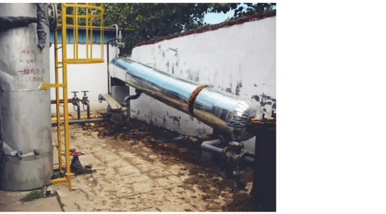
In order to validate the accuracy of the numerical simulation and validate the improved separa-tion resulting from structural parameter optimizasepara-tion, a field experiment was performed for comparison. An inclined oil/water separation device was manufactured based on the optimized model parameters (Fig 9), installed at Metering Station 20# in Block XX of an oilfield, and compared to the inclined oil/water separator without structural optimization used in Metering Station 15# in the same block.
Table 5. A comparison between the result of the validation experiment and the first three groups of the simulation results.
Experiment No. Water content at the oil outlet Oil content at the water outlet Oil/water separation efficiency
Range analysis Experiment 4 44.31% 0.50% 95.0%
Experiment 14 79.15% 0.46% 95.4%
Experiment 31 49.36% 0.50% 95.0%
Computational analysis Validation experiment 39.67% 0.50% 95.0%
doi:10.1371/journal.pone.0124095.t005
Table 6. Comparison of the separation efficiencies before and after optimization of structural parameters.
Item Water content at the oil outlet Oil content at the water outlet Separation efficiency
Before the optimization of structural parameters 57.50% 0.95% 90.48%
After the optimization of structural parameters 39.67% 0.50% 95.0%
Experimental scheme
Many factors affect oil/water separation efficiency. Due to the limitations of the objective con-ditions, conducting experiments on the effects of numerous structural parameters on oil/water separation efficiency would have been inconvenient. Therefore, in order to validate the Fig 8. Oil volume distributions.(A) Before optimization and (B) After optimization.
doi:10.1371/journal.pone.0124095.g008
Fig 9. The field experiment on the inclined separator.
accuracy of the simulation results, the field experiment was only used to study the effects of in-clination and residence time on oil/water separation efficiency.
A field experiment was conducted to investigate the oil/water separation of the liquid pro-duced by Oil Production Crew Twelve at inclinations ranging from approximately 0° to 15° with a settling time of 6 min. In order to analyze the effect of inclination on oil/water separa-tion efficiency, the experimental results were compared to the numerical simulasepara-tion results as well as the results of the separation experiment of the inclined oil/water separator used at Me-tering Station 15#. After the optimal inclination was determined, the amount of liquid used in the separator was altered in order to study the effect of residence time on oil/water separation efficiency and indicate the optimal residence time for field applications.
Samples were obtained from the liquid inlet, oil outlet, and water outlet every two hours for each experiment; three samples were obtained from each source. The water contents of the three groups of samples were measured and averaged. The separation efficiency was calculated for each separator. The water contents of the samples were represented by volumetric water content for comparison with the numerical simulation results.
Analysis of the experimental results
(1) Inclination-separation efficiency. Based on the numerical simulation results, a field experiment was conducted on the inclined oil/water separator at inclinations of 0°, 9°, 12°, and 15° at the Metering Station. The changes in inclination yielded the oil/water separation efficien-cies shown inFig 10(S6 Table).
According toFig 10, the oil/water separation efficiency increased as the inclination in-creased for the same incoming liquid residence time. When the inclination ranged between ap-proximately 9° and 15°, the oil/water separation efficiency changed slightly; when the
inclination was equal to 12°, the oil/water separation was most effective, with a separation effi-ciency of 96.84%.
Fig 10. Inclination-separation efficiency.
When the inclination ranged from 0° to 15°, the separation efficiency of the inclined oil/ water separator with optimized structural parameters improved under equal conditions. When the inclination was equal to 12°, the separation efficiency increased by 4.64%, or from 92.35% to 96.84%.
(2) Residence time-separation efficiency. Residence time has an important effect on sep-aration efficiency. When selecting the residence time, various factors should be considered. A shorter residence time is desirable as it satisfies the separation requirement. In order to study the effect of residence time on the separation efficiency of the inclined oil/water separator, the inclination was maintained at 12°, and the amount of liquid in the separator was altered in the field experiment.
According toFig 11(S7 Table), as the residence time increased, the oil/water separation ficiency increased rapidly. When the residence time reached 7 min, the oil/water separation ef-ficiency increased rapidly to greater than 97%, and the content of the water outlet decreased to 0.23%. As the residence time increased to greater than 7 min, the oil/water separation efficiency increased slightly. Therefore, a further increase in residence time would have an insignificant effect on the improvement of oil/water separation efficiency.
According toFig 10andFig 11, there were minor errors in the experimental and simulation data, but the changes in the separation efficiency resulting from the variations in inclination and residence time were basically consistent. This indicated the feasibility of the optimization of the structural parameters of the oil/water separator and the prediction of its separation effi-ciency through numerical simulations indicating that the structural parameter optimization of the oil/water separator.
Conclusions
In this paper, the inclined oil/water separator, which is used to improve the oil/water separa-tion efficiency for oilfields at the high water cut stage, was studied. Numerical simulasepara-tions were
Fig 11. Residence time-separation efficiency.
executed in order to analyze the distribution of oil and water in the separator and the effects of structural parameters on oil/water separation performance. Orthogonal array experiments were conducted to study the effects of structural parameters on oil/water separation efficiency, and optimal structural parameter values were obtained. The numerical simulations were vali-dated through a field experiment, and, thus, a basis for the design and widespread application of this type of separator was provided. Through these experiments, the following conclusions were drawn.
1. A direct understanding of the oil and water distribution and flow field within the separator was obtained through numerical simulations. The separation efficiency of the inclined sep-arator was higher than that of the conventional horizontal sepsep-arator under the same conditions.
2. The structural parameters had different effects on the oil/water separation efficiency. The horizontal position, hole number, and hole diameter of the dispenser had significant effects on the separation efficiency, whereas the longitudinal position of the dispenser and the water weir position had insignificant effects on the separation efficiency.
3. Orthogonal array experiments were conducted to study the effects of the structural parame-ters on the oil/water separation efficiency, and optimal structural parameparame-ters were obtained. After optimization of the structural parameters, the oil/water separation efficiency increased by 4.996% to a value of 95%.
4. A field experiment was conducted on the inclined oil/water separator at Metering Station 20# in Block XX of an oilfield. The results indicated that the inclined oil/water separator had a high handling capacity and a significant separation effect. After comparing these re-sults to those of the numerical simulation, some differences were found, but the effects of the structural parameters on the separation efficiency were consistent in both data sets. Therefore, optimizing the structure of the oil/water separator and predicting its separation efficiency would be feasible.
Supporting Information
S1 Table. Statistics concerning the separation characteristics at different inclinations. (DOC)
S2 Table. An array of the influential factors and their levels. (DOC)
S3 Table. Orthogonal experiments and results. (DOC)
S4 Table. The statistics concerning the results of the range analysis. (DOC)
S5 Table. Optimal values for the parameters. (DOC)
S6 Table. The effect of inclination on oil/water separation efficiency. (DOC)
Author Contributions
Conceived and designed the experiments: LQC KH. Performed the experiments: KH. Analyzed the data: SJW. Contributed reagents/materials/analysis tools: SJW HFL. Wrote the paper: SJW HFL LJZ.
References
1. Liu YH. The study of high efficiency inclined separator for free-water. M.Sc. Thesis, Tianjin University. 2009.
2. Wang HM, Liang Z. Design of the inclined plate gravity gas-liquid separators. Chem Eng & Mach. 2009; 36(1): 13–16.
3. Deng ZA, Chen TK, Luo YS, Wang HJ, Zhu YQ. Motion characteristics of liquid drops in water-washing flow field of oil-water separator. China Petrol Mach. 2006; 34(5): 18–21.
4. Liu XM, Tan RH, Liu YM. Mathematical model and numerical simulation of turbulent for hydrocyclonic separation. Fluid Mach. 2006; 34(10): 13–16.
5. Frising T, Noïk C, Dalmazzone C. The liquid/liquid sedimentation process: from droplet coalescence to technologically enhanced water/oil emulsion gravity separators: a review. J Disper Sci Technol. 2006; 27(7): 1035–1057.
6. Andresen PAK, Arntzen R., Sjøblom J. Stability of model emulsions and determination of droplet size distributions in a gravity separator with different inlet characteristics. Colloid Surface A. 2000; 170(1): 33–44.
7. Klasson KT, Taylor PA, Walker JF. Jr, Jones SA, Cummins RL, Richardson SA. Modification of a cen-trifugal separator for in-well oil-water separation. Sep Sci Technol. 2005; 40(1–3): 453–462.
8. Lv YL, He LM, Wang GD, Ni LY. Numerical simulation of flow field inside gravitational separator with dif-ferent internals. China Petrol Mach. 2008; 36(2): 12–16.
9. Wang GD, He LM, Lv YL, Chen ZY. Study on oil-water separating behavior of gravity separator. Acta Petrolei Sinica. 27(6): 112–115.
10. Hou XR. The numerical simulation on properties of gravity-type oil-water separator. M.Sc. Thesis, Da-lian Maritime University. 2011.
11. Zhang L. Research on the hydrodynamics of a primary oil-water separator. M.Sc. Thesis, Tianjin Uni-versity. 2005.
12. Lu YJ, Xue DS. A mathematical model for gravity oil/water separation. Acta Petrolei Sinica. 1999; 15 (3): 34–40.
13. Liu S, Su QW, Huang K, Li XZ, Jiang Y. Numerical simulation of flow field of the inclined oil-water sepa-rator. J Sw Petrol Univ (Sci Technol Edit). 2012; 34(6): 147–152.
14. Gao XF, Shi WD, Zhang DS, Zhang QH, Fang B. Optimization design and test of vortex pump based on CFD orthogonal test. T Chinese Soc Agr Mach. 2014; 45(5): 101–106.
15. Jia C, Zhang K, Zhang QY, Xu K. Research on multi-factor optimization of underground laminated salt rock storage group based on orthogonal experimental design. Rock Soil Mech. 2014; 35(6): 1718–
1726.