www.atmos-meas-tech.net/6/2207/2013/ doi:10.5194/amt-6-2207-2013
© Author(s) 2013. CC Attribution 3.0 License.
Atmospheric
Measurement
Techniques
Geoscientiic
Geoscientiic
Geoscientiic
Geoscientiic
Measurements on pointing error and field of view of Cimel-318 Sun
photometers in the scope of AERONET
B. Torres1,2, C. Toledano1, A. Berj´on3, D. Fuertes1, V. Molina1, R. Gonzalez1, M. Canini4, V. E. Cachorro1, P. Goloub2, T. Podvin2, L. Blarel2, O. Dubovik2, Y. Bennouna1, and A. M. de Frutos1
1Group of Atmospheric Optics, Valladolid University, Valladolid, Spain
2Laboratoire d’Optique Amosph´erique – UMR8518, Universit´e des Sciences et Technologies de Lille,
Villeneuve d’Ascq, France
3Izana Atmospheric Research Center, Spanish Meteorological Agency, Tenerife, Spain 4CIMEL Electronique, Paris, France
Correspondence to:B. Torres (benjamin@goa.uva.es)
Received: 23 February 2013 – Published in Atmos. Meas. Tech. Discuss.: 25 March 2013 Revised: 16 July 2013 – Accepted: 17 July 2013 – Published: 30 August 2013
Abstract.Sensitivity studies indicate that among the diverse error sources of ground-based sky radiometer observations, the pointing error plays an important role in the correct re-trieval of aerosol properties. The accurate pointing is spe-cially critical for the characterization of desert dust aerosol. The present work relies on the analysis of two new mea-surement procedures (cross and matrix) specifically designed for the evaluation of the pointing error in the standard in-strument of the Aerosol Robotic Network (AERONET), the Cimel CE-318 Sun photometer. The first part of the analysis contains a preliminary study whose results conclude on the need of a Sun movement correction for an accurate evalua-tion of the pointing error from both new measurements. Once this correction is applied, both measurements show equiva-lent results with differences under 0.01◦in the pointing error estimations. The second part of the analysis includes the in-corporation of the cross procedure in the AERONET routine measurement protocol in order to monitor the pointing error in field instruments. The pointing error was evaluated using the data collected for more than a year, in 7 Sun photometers belonging to AERONET sites. The registered pointing error values were generally smaller than 0.1◦, though in some in-struments values up to 0.3◦ have been observed. Moreover, the pointing error analysis shows that this measurement can be useful to detect mechanical problems in the robots or dirt-iness in the 4-quadrant detector used to track the Sun. Specif-ically, these mechanical faults can be detected due to the sta-ble behavior of the values over time and vs. the solar zenith
angle. Finally, the matrix procedure can be used to derive the value of the solid view angle of the instruments. The method-ology has been implemented and applied for the characteriza-tion of 5 Sun photometers. To validate the method, a compar-ison with solid angles obtained from the vicarious calibration method was developed. The differences between both tech-niques are below 3 %.
1 Introduction
The AErosol RObotic NETwork (AERONET, Holben et al., 1998) program was started by the National Aeronautics and Space Administration (NASA) in the 1990s, in collabora-tion with PHOTONS (Laboratoire d’Optique Atmospherique – LOA, University of Lille), as a federation of networks with regional or national extent deployed on ground in the form of stations for monitoring atmospheric aerosols. AERONET aims at providing reliable monitoring of global aerosol op-tical and microphysical properties, to facilitate the charac-terization of the aerosol properties, the validation of satellite products related to the aerosol as well as the synergy with other instrumentation (lidar, surface radiation, in situ aerosol, etc.).
AERONET instrument is the CE-318 manufactured by Cimel Electronique. This is an automatic Sun and sky radiometer, equipped with 8 or 9 spectral channels covering the spectral range 340–1640 nm. It performs both direct Sun measure-ments and sky radiance observations in the almucantar and principal plane configurations (Holben et al., 1998).
The AERONET inversion algorithm, described in Dubovik and King (2000) (also Dubovik et al., 2000, 2002, 2006), provides the aerosol information from two kinds of measurements: spectral data of direct Sun radiation extinc-tion (i.e., aerosol optical depth) and angular distribuextinc-tion of sky radiance. The latter contains essential information for retrieving the aerosol phase function and optical aerosol properties. Using this information, important aerosol optical and microphysical parameters, such as the particle size distribution (Nakajima et al., 1983, 1996) and complex refractive index or single scattering albedo (Dubovik and King, 2000; Dubovik et al., 2006), are derived.
The work of Dubovik et al. (2000) describes an accuracy analysis of the AERONET inversion code considering differ-ent error sources. Among the differdiffer-ent error sources, a pos-sible azimuth angle error during the pointing process is also accounted for. Precisely, one of the most important results of the study is that an accurate azimuth angle pointing is criti-cal for the characterization of desert dust aerosol. The zenith pointing accuracy, as analyzed by Torres (2012) is shown to be critical for the principal plane retrievals.
However, an evaluation of the pointing error in the Cimel CE-318 Sun photometers has not been done yet. The present work analyzes the first results of two new measurements (also called “scenarios” following the Cimel terminology), denominated “cross” and “matrix” and integrated in the CE-318, which have been developed for a characterization of the pointing error. As will be shown, these measurements will not be only useful to characterize the azimuth pointing error, but they will also be used to estimate the zenith pointing er-ror whose perturbations in the inversion procedure are men-tioned above. The continuous monitoring of this pointing ac-curacy can also be used to monitor instrument performance in the field.
Finally, the matrix measurement allows calculating the field of view (FOV) of the Sun photometer. This character-istic is of great importance in any Sun photometer, but the need for an accurate determination (beyond the manufac-turer’s specifications) arises from the fact that the field of view can be used to calibrate the radiance channels using the vicarious method (Li et al., 2008). Both field and laboratory measurements of the FOV can be used as a calibration check for quality assurance.
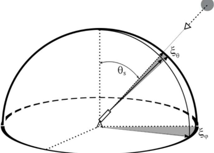
Fig. 1.Figure used to describe the pointing error. Dashed vector pointing towards the Sun represents the correct pointing, while solid line represents a biased pointing. Shading areas are the projection of this error in spherical coordinates:ξϕandξθ.
2 Theoretical basis
2.1 Pointing error
2.1.1 Definition
Pointing error (see Fig. 1) is defined as the angle between the Sun position (correct pointing) and the erroneous point-ing direction. As Sun photometers are moved by two motors, azimuth and zenith axes, the value of the pointing error,2ξ, is normally given in spherical coordinates:
2ξ=2ξ(ξϕ, ξθ). (1)
Unfortunately, the procedures conceived to calculate the pointing error generateξϕandξθ but not the “total” pointing error2ξ. So, the relation betweenξϕ,ξθ and2ξ should be obtained. Note, here, that if the pointing error is sufficiently small, it can be considered as an infinitesimal displacement (given in spherical coordinates) and therefore the relation in Eq. (1) could be defined as
2ξ=2error(ξϕ, ξθ)=ξθθˆ+sinθsξϕϕˆ
2ξ=
q
ξθ2+sinθs2ξϕ2.
(2)
To calculate the general relation of Eq. (1), the concept of scattering angle needs to be defined.
2.1.2 Scattering angle
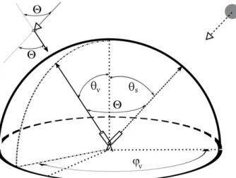
Fig. 2.Figure used to describe the scattering angle in terms of solar position and the observation angle.
observed by a detector. In our particular case, where the de-tector is a ground-based Sun photometer, the Sun can be con-sidered to be in the infinite and the scattering angle is equiv-alent to the angle formed by the directions of the Sun and the observation from the detector; see Fig. 2.
Then, the relation between the scattering angle, the so-lar position and the observation angle can be written as in Vermeulen (1996):
cos(2)=cos(θs)cos(θv)+sin(θs)sin(θv)cos(ϕv−ϕs), (3)
where2is the scattering angle,ϕvandθvare the observation
azimuth and zenith angle, andθs the solar zenith angle. In
the representation system, the solar azimuth angle (ϕs) can
be taken as the azimuth origin and its value set to zero. 2.1.3 Pointing errors described in terms of the
scattering angle
Revising both definitions, pointing error and scattering angle, it is easy to observe how the pointing error can be re-defined as the scattering angle of the erroneous pointing direction. If
ξϕ andξθ are the spherical coordinates of the pointing error, using Eq. (3), their relation with the scattering angle can be written as
cos(2ξ)=cos(θs)cos(θs+ξθ)
+sin(θs)sin(θs+ξθ)cos(ξϕ),
(4) which expresses the exact relation of the total pointing error in terms ofξϕandξθ. If we develop cos(θs+ξθ)and sin(θs+ ξθ), then
cos(2ξ)=cos(θs)[cos(θs)cos(ξθ)−sin(θs)sin(ξθ)] (5)
+sin(θs)cos(ξϕ)[cos(θs)sin(ξθ)+sin(θs)cos(ξθ)] (6)
=cos(θs)2cos(ξθ)−sin(θs)cos(θs)sin(ξθ) (7)
+sin(θs)cos(θs)sin(ξθ)cos(ξϕ). (8)
If again we only consider small errors, sin(ξθ)can be ap-proximated, rejecting terms from the third derivative, asξθ, and cos(ξθ)eliminating terms from the fourth derivative as 1−ξθ2
2. The same is valid forξϕ, obtaining
cos(2ξ)=cos2(θs)−cos2(θs) ξθ2
2 −sin(θs)cos(θs)ξθ
+sin(θs)cos(θs)ξθcos(ξϕ)
+sin2(θs)(1+ ξθ2ξϕ2
4 −
ξθ2
2 −
ξϕ2
2)
(9)
and then
cos(2ξ)=1+sin(θs)cos(θs)sin(ξθ)(cos(ξϕ)−1)
−(cos2(θs) ξθ2
2 +sin
2(θ s)
ξθ2
2)
−sin2(θs) ξϕ2
2 +sin
2(θ s)
ξθ2ξϕ2
4 cos(2ξ)=1−
ξθ2
2 −sin
2(θ s)
ξϕ2
2
−sin(θs)cos(θs) ξθξϕ2
2 +sin
2(θ s)
ξθ2ξϕ2
4 ,
(10)
and at this point, if we consider again only those terms until the second order, the last two terms in Eq. (10) can be elimi-nated. On the other hand, if we also approximate cos(2ξ)as 1−2
2
ξ 2 , then
1−2
2
ξ 2 =1−
ξθ2
2 −sin
2(θ s)
ξϕ2
2
H⇒22ξ=ξθ2+sinθ2ξϕ2,
(11)
recovering the expression in Eq. (2).
Taking into account that the pointing errors will not be larger than 1◦, all the approximations made (which rejected terms from the third order) are valid and, therefore, point-ing errors can be separated into their azimuth and zenith components.
The first tests done in order to characterize the pointing error, presented in the next section, confirmed this result: the zenith component of the error,ξθ, was constant and the az-imuth one,ξϕ, was also constant if it was multiplied by sinθs.
Therefore, the pointing error can be seen as a consistent mag-nitude, intrinsic to every photometer, which can be defined as the scattering angle between the sunbeam and the direction in which its detector is pointing.
In order to make the description easier,ξθ andξϕ, which are related to the two motor movements (zenith and azimuth), will be denoted from now on as zenith and azimuth error, respectively. On the other hand, total vertical and horizon-tal error will be denoted 2ξθ =ξθ and 2ξϕ=sinθsξϕ,
2.2 Field of view of the Sun photometers
2.2.1 Definition
Ideally, the solid angle in a radiance measurement is sup-posed to be infinitesimal. However, the solid angle is finite in the Sun photometers, and this fact could cause some distur-bances in the radiance value.
According to the Cimel company, manufacturer of the Sun photometer Cimel-318, the value of the field of view1in the current Sun photometers is 1.2◦while in the old versions it was 2.4◦. The field of view is an important characteristic of the Sun photometers: in radiance measurements, a large field of view can yield undesired averaging of radiances at sky re-gions near the Sun in which the change of radiance with the scattering angle is steep. On the other hand, the direct solar irradiance measurements get biased by the amount of aureole radiation that is assumed to be direct solar radiation. An in-vestigation on this particular topic in the frame of AERONET has been recently published (Sinyuk et al., 2012).
2.2.2 Vicarious
The so-called vicarious calibration method (Li et al., 2008) provides a radiance calibration given that an irradiance cali-bration and the solid view angle are known. The radiance (L) can be defined as
L= dE
dcos(θ ), (12)
whereEis the irradiance,the solid angle andθ is the an-gle between the surface normal direction and the specified (incidence or view) direction.
For small solid angles at normal incidence, the radiance can be approximated as
L=E
. (13)
The solid view angle of the instrument is just related to the geometry, provided that the irradiance (used for direct Sun observations) and the radiance (used for scattered sky radiance measurement) channels are measured with the same optical components, as is the case for the last generation of Cimel Sun/sky radiometers. The different electronic amplifi-cation used in each case must be taken into account. All the necessary information to derive the solid angle is indicated by Li et al. (2008, see Eq. 9).
In the cited work by Li et al. (2008), the authors derive the solid view angle from a set of irradiance and radiance calibrations, the latter made using an integrating sphere with known radiance output. In this work, we will apply the vi-carious method to derive the field of view. This estimation
1Note that the relation between the solid angle [sr] and field of view [radian] can be expressed as:=2π(1−cosθ )beingθ the field of view divided by two.
is based on the AERONET direct Sun and radiance calibra-tions; therefore it is independent of the geometrical measure-ments (in the laboratory or using the Sun as a source) of the field of view that are described in the next section. A compar-ison of results from 3 instruments will be presented to carry out a first consistency check between methods.
3 New procedures: matrix and cross
Two new procedures, matrix and cross, have been developed with the aim of evaluating the pointing quality of the Sun photometers. The description of both of them, as well as the different implementations accomplished in order to make them operative, are presented in this section.
Before describing the new procedures, it is necessary to briefly explain how the Cimel Sun photometer points at the Sun during its automated operation. The photometer robot has origin positions in both the zenith and azimuth mo-tors. These are found with the so-called PARK procedure, or scenario. Once the parking position is achieved, the instru-ment tries to find the Sun following an astronomical calcula-tion (GOSUN scenario) based on site coordinates and time. Due to incorrect leveling or robot orientation this position is usually not perfect. Finally a 4-quadrant detector is used (TRACK scenario) to find the exact solar position. The 4-quadrant must be previously adjusted (initially by the man-ufacturer) so that the instrument finds the position of max-imum signal on the detector while pointing at the Sun or a solar simulator, which is assumed to be the optical axis of the system. The adjustment can be lost due to several rea-sons: incorrect manipulation for example during transport, dirtiness on the 4-quadrant window, deficient alignment dur-ing maintenance, etc.
Other causes of a bad pointing can be also related to the mechanical performance of the tracking robot, which can have some slack in the motors or loose screws, or even arise from incorrect instrument setup, for instance if some cable does not allow free instrument movement. However, these last cases result in not finding the Sun at all within the field of view and are therefore easy to detect.
Fig. 3.Explanation of the matrix procedure in the subfigure on the left. On the right, a measurement taken at the Lille site on 22 Septem-ber 2010 at 12:47:07 LT.
3.1 Matrix measurement
3.1.1 Description
The matrix measurement starts with go-sun and track proce-dures (pointing at the Sun), and afterwards the Cimel moves towards the right1ϕ=1◦ and down 1θ= −1◦ (1). From this point it starts scanning the area around the Sun, going from down to up and right to left as plotted in Fig. 3 (on the left). As we can see in the figure, each data point represents a 0.1◦ movement to the left from1ϕ=1◦ to1ϕ= −1◦, which results in 21 measurements. In each of these measure-ments the Cimel covers all the zenith angles from1θ= −1◦ to1θ=1◦in 0.1◦ steps, while keeping the azimuth angle fix, and records a total of 21 measurements. An example of a matrix measurement is given in Fig. 3 (on the right) taken at the Lille site on 22 September 2010 at 12:47:07 LT.
Time is recorded for each measurements, right–left move-ment. That sequence lasts around 10 s; therefore every piece of data is obtained more or less every half a second. The total time used for the whole matrix measurement is 3.5 min. 3.1.2 Sun correction in matrix procedure
The image produced by the matrix (Fig. 3 on the right) seems to be wrong at first glance. The cause of this strange result is the Sun movement during the matrix measurement. In or-der to illustrate how the Sun movement affects our measure-ments, we show a brief study of how fast the Sun moves in angular terms at middle latitudes. For this test, we used the algorithm presented by Reda and Andreas (2004), which
1Hereafter the azimuth displacement of the Sun photometer mo-tor will be called1ϕ, the zenith one being represented as1θ.
5 10 15 20
0 0.002 0.004 0.006 0.008 0.01
Hour
Angle variation [degrees/sec]
zenith azimuth
5 10 15 20
0 0.002 0.004 0.006 0.008 0.01
Hour
Angle variation [degrees/sec]
zenith azimuth
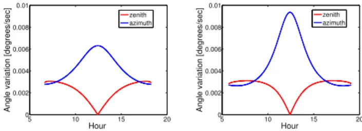
Fig. 4.Azimuth and zenith absolute Sun variations per second at the Valladolid site during the winter on the left, and during the summer on the right.
will be later used to discount the solar movement in the whole pointing error study. Using the mentioned algorithm, in Fig. 4, the zenith and azimuth absolute Sun variation per second at the Valladolid site (middle-latitude station) are rep-resented, for the winter, in the subfigure on the left, and for the summer in the subfigure on the right.
The zenith variation never gets higher than 0.003◦s−1, reaching this value at sunrise and at sunset, and its mini-mum at noon being 0◦s−1. Looking at the figures, it does not show a seasonal variability. On the other hand, the azimuth variation is much higher and season-dependent: the variation reaches its maximum of 0.01◦s−1 at noon in the summer. Its minimum of 0.003◦s−1takes place at dawn and at sun-set (same value as the maximum of solar variation). With all these data, we can estimate that the bias introduced during the matrix measurement at a middle-latitude station is be-tween 0◦and 0.6◦in the zenith and between 0◦and 2◦in the azimuth.
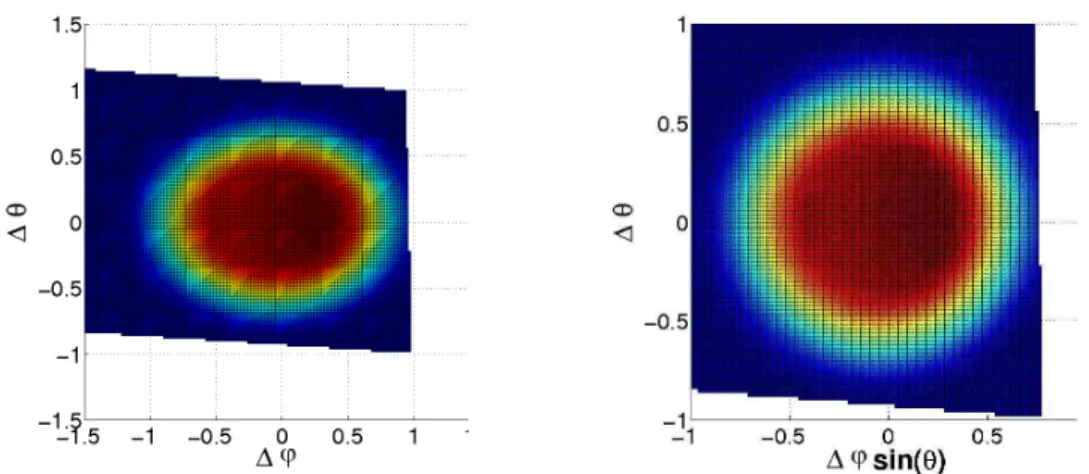
Fig. 5.Subfigure on the left shows a matrix measurement taken at the Lille site on 22 September 2010 at 12:47:07, corrected for the Sun displacement. Subfigure on the right displays the same measurement but with the azimuth displacement multiplied by sin(θs).
Fig. 3 is plotted in Fig. 5, on the left; note that in the figure on the right,1ϕsin(θs)is put instead of1ϕ. The fact that in
the first plot an ellipse appears while the second one shows a sphere confirms what we have already settled: even though the Sun photometer motor does the steps by1ϕ, the hori-zontal Sun photometer pointing error should be evaluated in terms of1ϕsin(θs).
3.2 Cross measurement
3.2.1 Description
The Sun cross measurement starts tracking the Sun and then it moves downwards,1θ= −4◦. From this point, it moves up recording data for every step of 0.2◦ (measurement 0). Once it gets to1θ=4◦it repeats the movements but back-wards (measurement 1). Afterback-wards, it points to the Sun again and moves right,1ϕ=4◦. From there, it moves left recording data every 0.2◦, as well, until1ϕ=4◦ (measure-ment 2), and then it repeats the move(measure-ment to the right until
1ϕ=4◦again (measurement 3). The data obtained between
−2◦ and 2◦ in both axes are measured with low gain (Sun channel 1) like in the matrix measurement, and the rest of the data are recorded with a higher gain (aureole) channel. Nevertheless, the relevant part of the measurement is the first set of data.
3.2.2 Sun correction in cross procedure
Cross measurements need a correction due to the solar dis-placement too. Checking the timing recorded in the data files, from the beginning of the two track procedures (considering tracking time as the time recorded in the 0 and 2 measure-ments) until the end of measurements 1 and 3, the Sun pho-tometer uses approximately 40 s. The correction is especially critical for azimuth angles during the summer season, when a bias of 0.4◦would appear otherwise. The cross measurement
−20 −1 0 1 2 2000
4000 6000 8000 10000 12000 14000
Angle [°]
Digital Counts scen 3 scen 2 scen 1 scen 0
−20 −1 0 1 2 2000
4000 6000 8000 10000 12000 14000
Angle [°]
Digital Counts scen3 scen2 scen1 scen0
Fig. 6.On the left, cross measurements taken at the Valladolid site on 5 August 2010 at 13:41. The subfigure on the right shows the same measurement after applying a Sun movement correction on the data.
done at the Valladolid site on 5 August 2010 at 13:41 is shown in Fig. 6 with and without the Sun movement cor-rection. In the example, the necessity of this correction can be seen, especially for measurement 3 (green line), which is the second measurement of the azimuth cross, as previously indicated.
4 Pointing error estimations
4.1 Methodology
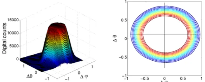
Fig. 7.Figure on the left, matrix measurement done at the Valladolid site on 5 August 2010 at 13:41 with a SZA of 54.77, on the right its contour map for levels from 20 % to 80 % of its maximum value (every 5 %).
The value of the pointing error is then estimated by calcu-lating all the centers and averaging them. A similar procedure is followed for the cross measurements. Using the data from measurements 0 and 1 (related to1θ) and measurements 2 and 3 (related to 1ϕ), the data is interpolated at different heights of its maximum value, in this case from 20 % to 80 % with steps of 10 %. It is important to emphasize again that the azimuth pointing estimation should be done as1ϕsin(θs),
and consequently after the calculation of the centers (done in terms of1ϕ resulting in ellipses instead of circles in the matrix analysis), every single point is multiplied by sin(θs)
to obtain the pointing error estimation. 4.2 Preliminary results
The first tests with the matrix and cross measurements were done in Valladolid during summer 2010 with photometer #353, and in Lille during the early autumn 2010 with tometers #042 and #047. We also did some tests with pho-tometers #420 and #143 in Valladolid during the autumn. Ta-ble 1 includes the dates and the description of all the data collected. Therefore, for these first tests, data were collected using 5 different Sun photometers.
The measurements from #047 are split because two differ-ent robots were used during the measuremdiffer-ent; when it was installed on the first robot, it showed some disagreements which are discussed separately. Once the photometer was set on the second robot, the disagreements disappeared.
The photometer number #420 was studied in 4 periods be-cause we deliberately misaligned its tracking system: num-bers (2) and (3) correspond to those measurements with the biased track system, while numbers (1) and (4) represent the tests when the photometer came to the calibration center and before it was sent back to its field site, once the tracking sys-tem was re-adjusted.
Tables 2 and 3 contain the average and the standard devi-ation of the pointing error for all the data except for that of photometer #047(1), which due to its aforementioned prob-lems is analyzed apart. We have not included the tests with #420(2)and #420(3)either, since their tracking system was
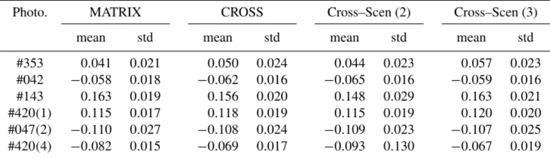
deliberately misaligned, and they will be also studied later. Table 2 shows the results obtained for the horizontal point-ing error (azimuth pointpoint-ing error multiplied by sin(θs)) and
Table 3 for vertical pointing error (or zenith pointing error). The same scheme is used for both tables: the column on the left presents the results obtained by the matrix, the sec-ond column the result obtained by the cross, while the third and four columns present the results for every cross branch individually.
The two procedures provide practically the same pointing errors with absolute differences under 0.01◦between them. This is a very important result as the measurements are inde-pendent and the methodology followed to calculate the point-ing error was done separately. Another important result is that the Sun photometers point toward the Sun with an er-ror under 0.1◦ except for photometer #143, whose tracking system seems to be biased 0.2◦in both axes.
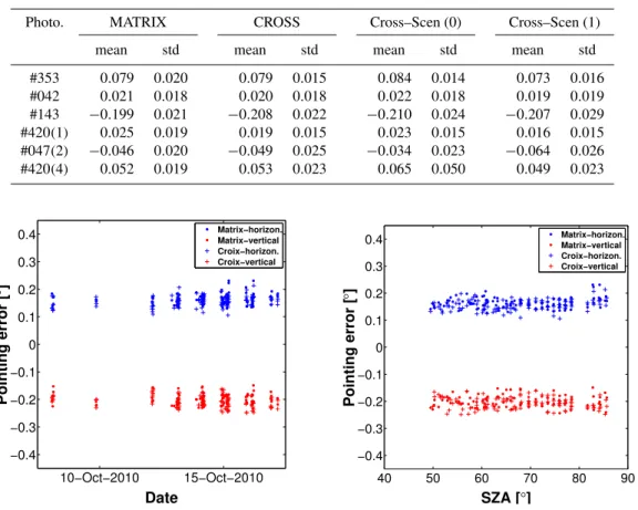
Using the results of this photometer (with the highest er-ror), the estimated pointing error of every single piece of data is plotted in Fig. 8 vs. date, on the left, and vs. the solar zenith angle (SZA) on the right in order to check whether there is any pointing error dependence on those parameters. The re-sults do not show any dependence either on the date or on the solar zenith angle.
However, the data range for both components of the point-ing error is around 0.07–0.08. The result is not surprising as in Tables 2 and 3 the standard deviation was 0.020–0.025 for all the photometers. This high dispersion could be ex-plained by the mechanical characteristic of the Cimel-318 robot which has a minimum step of 0.05◦ in azimuth and zenith. Note that the dispersion is also given in horizontal and vertical terms. As the solar zenith angles used for the measurements are very high there is almost no difference be-tween the two components. However, as the dispersion is a function of the azimuth and zenith components of the motor, it should be understood in these terms; therefore, we would expect the horizontal dispersion to get reduced for short so-lar zenith angles, which is already noticeable in Fig. 8 (blue points in the figure on the right) when SZA=50◦.
4.2.1 Detection of robot problems: #047
Looking at the values of photometer #047(1)in Table 4, there is no agreement between the matrix and cross results and not even between the two branches of the cross measure (mea-surement (2) and mea(mea-surement (3) for2ξϕ and measurement
(0) and measurement (1) for2ξθ). Moreover, standard
Table 1.Summary of the cross and matrix measurements done in the preliminary result tests.
Station Photometer Starting date Ending date Valid measur.
Valladolid #353 04/08/2010 06/08/2010 19 Lille #042 22/09/2010 24/09/2010 38 Valladolid #143 08/10/2010 17/10/2010 110 Lille #047(1) 09/10/2010 12/10/2010 107 Valladolid #420(1) 18/10/2010 18/10/2010 34 Lille #047(2) 21/10/2010 28/10/2010 65 Valladolid #420(2) 26/10/2010 01/11/2010 65 Valladolid #420(3) 02/11/2010 08/11/2010 91 Valladolid #420(4) 09/11/2010 11/11/2010 27
Table 2.Summary of the horizontal pointing error (2ξϕ=ξϕsin(θs), given in degrees) for several Sun photometers in the preliminary result tests.
Photo. MATRIX CROSS Cross–Scen (2) Cross–Scen (3)
mean std mean std mean std mean std
#353 0.041 0.021 0.050 0.024 0.044 0.023 0.057 0.023 #042 −0.058 0.018 −0.062 0.016 −0.065 0.016 −0.059 0.016 #143 0.163 0.019 0.156 0.020 0.148 0.029 0.163 0.021 #420(1) 0.115 0.017 0.118 0.019 0.115 0.019 0.120 0.020 #047(2) −0.110 0.027 −0.108 0.024 −0.109 0.023 −0.107 0.025 #420(4) −0.082 0.015 −0.069 0.017 −0.093 0.130 −0.067 0.019
4.2.2 Misalignment tests
Finally, the study of the instrument in which we deliberately misaligned its tracking system, number #420, is shown in Ta-ble 1: #420(2)and #420(3). The center estimations for both periods are represented in Fig. 10. Before the Sun photome-ter was installed, on the morning of 27 October 2010, the tracking system was misaligned (#420(2)). In order to inves-tigate an even higher pointing error, it was misaligned again during the afternoon of that day. This change is noticeable in Fig. 10 (on the left) where the pointing error values are differ-ent in the morning and in the afternoon on 27 October 2010. To conclude, in the right part of Fig. 10, the evolution of the pointing error on the following days is shown. There is a to-tal agreement for matrix and cross center estimations in this case, as well. Therefore, even when the tracking system is highly biased (values up to 0.5◦) the method is still valid. 4.2.3 Pointing error monitoring in the field
The previous analysis suggested that matrix and cross mea-surements are both valid methods to estimate the pointing errors as well as good indicators of different issues, such as robot problems or dirtiness in the quadrant detector (Tor-res, 2011). After this, the cross measurement was proposed (within AERONET annual calibration workshop) to be inte-grated as a part of the AERONET standard measurement pro-tocol, with a little modification: in order to be more precise
the cross spans from−2◦to 2◦, with 0.1◦steps. Matrix mea-surement was discarded for field operation because a lot of memory is needed to record the data.
In order to integrate the cross measurement in the mea-surement protocol, the Cimel company designed a new E-eprom (5.20 h) that adds 2 cross measurements per day to the usual measurement protocol. These are all CE-318NE (“ex-tended” model with 1640 nm channel). Note that the point-ing measurements in previous sections with the matrix and cross measurements were based on the 1020 nm Sun channel exclusively. Cimel Sun photometers have 2 optical channels (with 2 collimator tubes). Depending on the Cimel models, the sky measurements are taken with the second optical chan-nel (standard model) or with the same optical chanchan-nel (ex-tended model), given that ex(ex-tended models use the second channel for near infrared measurements at 1640 nm wave-length. The 4-quadrant detector is unique though; therefore the parallelism between tubes may play a role. The choice of an extended Cimel model for these measurements allows evaluating the pointing in both physical channels and pro-vides an estimation of the parallelism between the two opti-cal axes. This gives an estimation of the pointing error of the sky measurements in standard Cimels.
Table 3.Summary of the vertical pointing error (2ξθ=ξθ) of several Sun photometers in the preliminary result tests.
Photo. MATRIX CROSS Cross–Scen (0) Cross–Scen (1)
mean std mean std mean std mean std
#353 0.079 0.020 0.079 0.015 0.084 0.014 0.073 0.016 #042 0.021 0.018 0.020 0.018 0.022 0.018 0.019 0.019 #143 −0.199 0.021 −0.208 0.022 −0.210 0.024 −0.207 0.029 #420(1) 0.025 0.019 0.019 0.015 0.023 0.015 0.016 0.015 #047(2) −0.046 0.020 −0.049 0.025 −0.034 0.023 −0.064 0.026 #420(4) 0.052 0.019 0.053 0.023 0.065 0.050 0.049 0.023
10−Oct−2010 15−Oct−2010 −0.4
−0.3 −0.2 −0.1 0 0.1 0.2 0.3 0.4
Date
Pointing error [
°
]
Matrix−horizon. Matrix−vertical Croix−horizon. Croix−vertical
40 50 60 70 80 90 −0.4
−0.3 −0.2 −0.1 0 0.1 0.2 0.3 0.4
SZA [°]
Pointing error [
°
]
Matrix−horizon. Matrix−vertical Croix−horizon. Croix−vertical
Fig. 8.Estimated center for matrix and cross measurements variation with the date (left) and with the SZA (right) for photometer #143.
09−Oct−2010 11−Oct−2010
−0.2 −0.1 0 0.1 0.2
Date
Pointing error [
°
]
Matrix−horizon. Matrix−vertical Croix−horizon. Croix−vertical
Fig. 9.Estimated center for matrix and cross measurements for pho-tometer #047.
(“extended” model with 1640 nm channel). As an example, Fig. 11 shows the pointing error derived from crosses dur-ing 2012 for Sun photometer #627 in both physical chan-nels, corresponding to the UV visible and infrared chanchan-nels,
respectively. The two channels have different pointing axes and both of them stay within the prescribed specifications.
The pointing error observations derived from cross mea-surements have been shown to be very stable over time; therefore they would allow (a) correction of the pointing in the sky radiances, which could improve the inversion-derived products, and (b) detection of mechanical problems, as was already indicated in Sect. 4.2.1. In Fig. 12, the time series of pointing error in the zenith and zenith directions is shown for instrument #383. In the analyzed period the instrument was deployed at several sites (Autilla, Valladolid and Iza˜na). A mechanical problem of the first robot used at Autilla is clearly highlighted by the azimuth pointing error. The prob-lem is solved after the change of mounting robot. The in-stallation in Valladolid shows very low and stable pointing errors. The last period in Iza˜na seems to present some defi-ciency in the azimuth direction, very likely due to some robot problem again.
Table 4.Summary of the horizontal pointing error (2ξϕ=ξϕsin(θs)) and vertical pointing error (2ξθ =ξθ), both given in degrees, of photometer #047.
Photo. Error MATRIX CROSS Cross–Scen (2) Cross–Scen (3)
mean std mean std mean std mean std
#047(1) 2ξϕ −0.220 0.101 −0.125 0.102 −0.233 0.112 −0.020 0.095
Cross–Scen (0) Cross–Scen (1)
mean std mean std mean std mean std
#047(1) 2ξθ −0.061 0.017 −0.059 0.019 −0.055 0.019 −0.064 0.020
27−Oct−2010 31−Oct−2010
−0.6 −0.4 −0.2 0 0.2 0.4 0.6
Date
Pointing error [
°
]
Matrix−horizon. Matrix−vertical Croix−horizon. Croix−vertical
03−Nov−2010 06−Nov−2010
−0.6 −0.4 −0.2 0 0.2 0.4 0.6
Date
Pointing error [
°
]
Matrix−horizon. Matrix−vertical Croix−horizon. Croix−vertical
Fig. 10.Estimated center for matrix and cross measurements during the tests with the tracking system of Sun photometer #420.
−0.2 −0.1 0 0.1 0.2
−0.2 −0.1 0 0.1 0.2
Azimuth [°]
Zenith [
°
]
Visible Infrared
Photo#627
Fig. 11.Zenith and azimuth pointing error derived from cross mea-surements for Sun photometer #627 during 2012.
one existing in AERONET for aerosol optical depth mea-surements (fully described in Smirnov et al., 2000). To elim-inate from the analysis the different errors reported during the cross measurement (e.g., robot issues in Sun photome-ter #383; Fig. 12) automatically, the maximum differences
allowed between the branches, left–right and up–down, dur-ing the pointdur-ing error calculation has been 0.02◦(note that the final value of the pointing error is the average of these branches).
01−Mar−2012 01−Aug−2012 01−Jan−2013 −0.75
−0.5 −0.25 0 0.25 0.5 0.75
Date
Poiting error [
°
]
Zenith−1020nm
Azimuth−1020nm
Robot#1 Robot#2
Autilla Valladolid Izana
Photo#383
Fig. 12.Time series of zenith and azimuth pointing error derived from cross measurements for Sun photometer #383 during 2012.
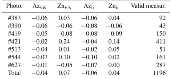
Table 5.Pointing error statistics for the 7 analyzed photometers in the azimuth (Az) and zenith (Zn) directions. The data are provided for the two physical channels, visible and infrared, in order to check also the parallelism between them.
Photo. Azvis Znvis Azir Znir Valid measur.
#383 −0.06 0.03 −0.06 0.04 92
#390 −0.06 −0.06 −0.08 −0.06 43
#419 −0.05 −0.08 −0.08 −0.09 150
#421 −0.02 0.24 −0.04 0.14 411
#513 −0.04 0.01 −0.02 0.05 51
#544 −0.07 0.10 −0.10 0.02 161
#627 −0.01 −0.05 −0.07 0.00 287
Total −0.04 0.07 −0.06 0.04 1196
5 Field of view calculations
5.1 Matrix measurements in field photometers
Nakajima et al. (1996) propose a method to estimate the field of view from similar measurements to the matrix pro-cedure. In this article, the field of view of the solar radiome-ter PREDE (standard instrument of the Skynet network) is calculated from a set of measurements similar to the matrix procedure. Basically, the field of view is obtained as follows:
F.O.V.=
Z Z
1A
E(x, y)
E(0,0)dxdy, (14)
wherex andy (in radians) are the polar coordinates that de-termine the position of the optical axis with respect to the position of the Sun.E(x, y)is the irradiance measurement at any point andE(0,0)is the irradiance at the center of the Sun.
In order to use Eq. (14) it is necessary to evaluate the measurementE(0,0)and, therefore, to know previously the
Table 6.Values of the field of view (in degrees) calculated during the preliminary tests using the Sun as a light source.
Photo. F.O.V std
#353 1.30 0.02 #042 1.27 0.03 #143 1.14 0.02 #047(2) 1.30 0.02 #420(1) 1.32 0.02 #420(2) 1.32 0.02 #420(3) 1.32 0.03 #420(4) 1.32 0.03
pointing error. Ifxcandycare the estimated pointing errors
(horizontal and vertical, respectively), then Eq. (14) can be expressed as
F.O.V.=X
i,j
E(xi, xj)1S(i, j )
E(xc, yc)
, (15)
wherei represents the variation in the horizontal (azimuth increment multiplied by sinθs) axes andj in the zenith one.
Using the photometers described in Table 1, in Table 6 calculated values for the field of view are represented. Pho-tometer #047 in its first part is not represented due to its robot problems. The values for the 5 photometers vary between 1.13◦and 1.32◦, which means a discrepancy of 10 % for the Cimel specified value of 1.2◦.
The different periods of miscalibration are considered sep-arately in photometer #420. The value obtained does not de-pend on the pointing accuracy.
5.2 Matrix measurements with a laser beam in the laboratory
Laser source
Mirror 1
Mirror 2
Lens 1 Lens 2
Sun photometer
Fig. 13.Optic design to measure the FOV of Sun photometers with a laser beam.
source, we have used a laser beam in the laboratory which has been previously expanded and collimated in order to get an almost punctual source2at infinity (see Fig. 13). We have introduced a spatial filter using an aperture of 12 µm situated in the focal plane of the microscope objective lens (lens 1 in Fig. 13 withf =16 mm). The collimator lens had a focal length of 30 cm, producing an expanding relation of about 1:20. After the beam is expanded, only the part limited by the entrance pupil of the photometer, which has a diameter around 5 mm, is used. Consequently, with both systems, ex-pander and optical filter, the uniformity of the beam is guar-anteed as well as the absence of coherence noise (speckle).
The utilization of a punctual source results not only in the value of the field of view (following the methodology given by Nakajima et al., 1996, and summarized in Eq. 14) but also with the opportunity to estimate the shape of the response of the field of view in the Sun photometer.
Figure 14 shows an example of a matrix measurement in photometer #143 using the laser beam in the laboratory. We can observe that the response of the field of view is practi-cally cylindrical and that the fall is straight, indicating that in the optical system of the Sun photometer the limit illumina-tion and full illuminaillumina-tion are the same.
Comparing this representation with the one obtained in Fig. 7 where the Sun was used as the source, we see that in that case the fall was softer due to the angular size of the Sun.
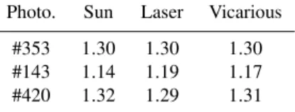
The experiences with the laser beam are quite recent and we have only measured three photometers: #143, #353 and #420. The result of the tests are in accordance with those ob-tained in the field (using the Sun as a source) with differences under 5 % as shown in Table 7. The FOV calculations from the vicarious method are also represented in Table 7, and the results agree better than 3 % with respect to the other tech-nique for both light sources.
2The angular size of any source can be estimated as the quotient between the size of the source, in this case 12 µm, and the focal length of the lens, which was 30 cm in the one used. With these data the angular size was about 0.0023◦in our experiments.
−1
0
1
−1
0
1
0
1000
2000
3000
4000
∆φ
∆θ
Digital counts
Fig. 14.Example of a matrix measurement using a laser beam with photometer #143
Table 7.Comparison of the field of view results (given in degrees) obtained using the Sun and a laser beam as a source.
Photo. Sun Laser Vicarious
#353 1.30 1.30 1.30 #143 1.14 1.19 1.17 #420 1.32 1.29 1.31
6 Discussion
As commented in the Introduction, the work of Dubovik et al. (2000) concludes that a possible error in the azimuth angle during the pointing process is critical for the characterization of desert dust aerosol. The study was done simulating only almucantar measurements and considering 1◦as a pointing error. After the tests shown here, such a value for the pointing error is unrealistic and an update to this work should be done considering the results obtained here.
In the work of Torres (2012), almucantar and principal plane measurements are simulated and inverted, afterwards, introducing vertical and horizontal pointing errors (2ξθ =ξθ
and2ξϕ=sinθsξϕ, respectively) of values 0.2
◦, 0.4◦and 1◦.
The analysis of the extreme case3of 0.4◦(also described in Torres et al., 2013) shows that this value of the point-ing error produces differences between 15 % and 20 % in the size distribution retrievals using principal plane geome-try. The differences in the almucantar simulations are signifi-cantly smaller: around 10 %. This type of error also produces variations in the optical parameters: thus, absolute errors up to 0.02 are found in the retrievals of the single scattering albedo for both geometries. Finally, we want to indicate that horizontal errors did not introduce any variations for both geometries.
According to the results presented here, the typical point-ing errors found in AERONET photometers stay within the range of tolerated uncertainties and would have no significant impact on the inversion-derived products. However in some cases larger errors have been detected that would yield biased retrievals, especially in the case of vertical error in the princi-pal plane geometry. Therefore the monitoring of the pointing performance in the case of Sun/sky radiometers shows up as a necessary task to maintain the data quality.
7 Conclusions
The pointing error of the Cimel-318 Sun photometer has been determined through the use of two new measurement procedures: cross and matrix. However, the raw data pro-duced by these new measurements have been shown to be insufficient for a correct evaluation of the pointing error, and a correction to account for Sun movement during the mea-surement had to be implemented.
The methodology proposed in this work was applied to several Sun photometers in a preliminary study. The results revealed that both measurement procedures, cross and ma-trix, are equivalent, with differences in the evaluation of the pointing error below 0.01◦. For this reason, and due to the large amount of memory that is needed to record the data of matrix measurements, only the cross procedure has been in-tegrated as part of the AERONET standard protocol for field measurements.
The analysis of the first results has indicated that, in gen-eral, the value of the pointing error in AERONET Sun pho-tometers is smaller than 0.1◦, though in some instruments values up to 0.3◦have been registered. Moreover, the point-ing error has been shown to have a stable behavior over time and is not dependent on the solar zenith angle. These features can be used to detect other problems during the measurement process, such as mechanical malfunction in the robots or dirt-iness in the 4-quadrant detector.
Using the matrix procedure, the field of view of five Sun photometers has been characterized obtaining values
3For most of the photometers with a field of view of 1.2◦this extreme value would be 0.35◦pointing error. However, the fact that some photometers analyzed here presented a value of the field of view around 1.3◦motivates us to enlarge the threshold up to 0.4◦.
between 1.13◦ and 1.32◦. The maximum discrepancy with respect to the Cimel specification (1.2◦) was 10 %. To ver-ify this technique, a second test in the laboratory has been applied on three Sun photometers using a laser beam as a punctual source. The results of these tests are in accordance with those obtained using the Sun as a source with differ-ences under 5 %. The use of the laser beam has also allowed us to certify that the shape of the response of the field of view is practically cylindrical, indicating that in the optical system of the Sun photometer, the limit illumination and the full il-lumination are the same.
Finally, the field of view of the same three Sun photome-ters have been also calculated using the so-called vicarious method. Differences under 3% were found with respect to the other technique for both Sun and laser source.
Acknowledgements. We thank the AERONET, PHOTONS, RIMA
and WRC staff for their scientific and technical support. Financial support was provided by the Spanish CICYT (CGL2009-09740 and CGL2011-23413, CGL2011-13085-E). The research leading to these results has received funding from the European Union Seventh Framework Programme (FP7/2007-2013) under grant agreement no. 262254 [ACTRIS]. We also thank the Environmental Council of the CyL Regional Government (Consejer´ıa de Medio Ambiente, Junta de Castilla y Le´on) for supporting this research.
Edited by: M. King
The publication of this article is financed by CNRS-INSU.
References
Dubovik, O. and King, M.: A flexible inversion algorithm for re-trieval of aerosol optical properties from Sun and sky radiance measurements, J. Geophys. Res. Atmos., 105, 20673–20696, doi:10.1029/2000JD900282, 2000.
Dubovik, O., Smirnov, A., Holben, B., King, M., Kaufman, Y., Eck, T., and Slutsker, I.: Accuracy assessments of aerosol optical properties retrieved from Aerosol Robotic Network (AERONET) Sun and sky radiance measurements, J. Geophys. Res. Atmos., 105, 9791–9806, doi:10.1029/2000JD900040, 2000.
Dubovik, O., Holben, B., Eck, T., Smirnov, A., Kaufman, Y., King, M., Tanre, D., and Slutsker, I.: Variability of absorption and optical properties of key aerosol types observed in world-wide locations, J. Atmos. Sci., 59, 590–608, doi:10.1175/1520-0469(2002)059<0590:VOAAOP>2.0.CO;2, 2002.
Holben, B., Eck, T., Slutsker, I., Tanre, D., Buis, J., Setzer, A., Vermote, E., Reagan, J., Kaufman, Y., Nakajima, T., Lavenu, F., Jankowiak, I., and Smirnov, A.: AERONET – A feder-ated instrument network and data archive for aerosol character-ization, Remote Sens. Environ., 66, 1–16, doi:10.1016/S0034-4257(98)00031-5, 1998.
Li, Z., Blarel, L., Podvin, T., Goloub, P., Buis, J.-P., and Morel, J.-P.: Transferring the calibration of direct solar irradiance to diffuse-sky radiance measurements for CIMEL Sun-diffuse-sky radiometers, Appl. Opt., 47, 1368–1377, doi:10.1364/AO.47.001368, 2008. Nakajima, T., Tanaka, M., and Yamauchi, T.: Retrieval of the
optical-properties of aerosols from aureola and extinction data, Appl. Opt., 22, 2951–2959, 1983.
Nakajima, T., Tonna, G., Rao, R., Boi, P., Kaufman, Y., and Hol-ben, B.: Use of sky brightness measurements from ground for remote sensing of particulate polydispersions, Appl. Opt., 35, 2672–2686, doi:10.1364/AO.35.002672, 1996.
Reda, I. and Andreas, A.: Solar position algorithm for so-lar radiation applications, Sol. Energy, 76, 577–589, doi:10.1016/j.solener.2007.01.003, 2004.
Sinyuk, A., Holben, B. N., Smirnov, A., Eck, T. F., Slutsker, I., Schafer, J. S., Giles, D. M., and Sorokin, M.: Assessment of error in aerosol optical depth measured by AERONET due to aerosol forward scattering, Geophys. Res. Lett., 39, L23806, doi:10.1029/2012GL053894, 2012.
Smirnov, A., Holben, B., Eck, T., Dubovik, O., and Slutsker, I.: Cloud-screening and quality control algorithms for the AERONET database, Remote Sens. Environ., 73, 337–349, doi:10.1016/S0034-4257(00)00109-7, 2000.
Torres, B.: Pointing errors in sky radiance measurements from sun-photometers. Influence on inversion-retrieved aerosol properties, Observations and modeling of aerosol and clouds properties for climate studies, Paris, France, 2011.
Torres, B.: Study on the influence of different error sources on sky radiance measurements and inversion-derived aerosol products in the frame of AERONET, Ph.D. thesis, Universidad de Valladolid, 2012.
Torres, B., Dubovik, O., Toledano, C., Berjon, A., Cachorro, V. E., Lapyonok, T., and Goloub, P.: Sensitivity of aerosol retrieval to geometrical configuration of ground-based sun/sky-radiometer observations, Atmos. Chem. Phys. Discuss., 13, 6851–6921, doi:10.5194/acpd-13-6851-2013, 2013.