105 DOI: 10.21279/1454-864X-16-I1-018
© 2015. This work is licensed under the Creative Commons Attribution-Noncommercial-Share Alike 4.0 License.
COMPARISON BETWEEN FORMULAS OF MAXIMUM SHIP SQUAT
Petru Sergiu SERBAN 1
Valeriu Nicolae PANAITESCU 2
1 PhD Student, Department of Navigation and Naval Transport, “Mircea cel Bătrân” Naval Academy,
Constanța, Romania, [email protected]
2 Prof. emeritus, PhD, Department of Hydraulics, Hydraulic Machines and Environmental Engineering,
Politehnica University Bucharest, Romania
Abstract: Ship squat is a combined effect of ship’s draft and trim increase due to ship motion in limited navigation conditions. Over time, researchers conducted tests on models and ships to find a mathematical formula that can define squat. Various forms of calculating squat can be found in the literature. Among those most commonly used are of Barrass, Millward, Eryuzlu or ICORELS. This paper presents a comparison between the squat formulas to see the differences between them and which one provides the most satisfactory results. In this respect a cargo ship at different speeds was considered as a model for maximum squat calculations in canal navigation conditions.
Keywords: ship squat, formula, channel configuration, cargo ship.
INTRODUCTION
A phenomenon that occurs on vessels in
channels, rivers, canals and harbors is ship
squat, which may be defined as the sinkage and/or trimming of the ship due to pressure changes along the ship length in shallow waters. The trim change can be explained by hydrodynamic interactions between the ship and the bottom due to speed and pressure distribution change. The squat effect is directly related to ship dimensions, its speed and water depth; therefore, it interests port and waterway designers as much as masters and naval architects [1].
Ship squat phenomenon has been the subject of studies in many ways for a long time. In general, most researches rely on empirical formulas, experimental tools or numerical (Computational Fluid Dynamics) techniques, among which the first two types are more widely used [2].
Squat formulas have been developed for estimating maximum squat for vessels operating in restricted and open water conditions with satisfactory results. Some have been measured on real ships and some on models [3].
Scientific research on ship squat was started by Constantine (1960), which studied the phenomenon for subcritical, critical and
supercritical speeds. In subcritical domain, Tuck
(1966) demonstrated that in open water conditions of constant depth, the sinkage and trimming of the vessel varies linearly with depth Froude number. This theory was developed by others, such as Beck (1975) for dredged channels, Naghdi and Rubin (1984), Cong and Hsiung (1991), Jiang and
Henn (2003) or Gourlay (2008) [4].
Current researches on this phenomenon are limited to experiments on scale models for an
accurate mathematical expression of ship squat. The literature presents various formulas of squat,
the most commonly used being those of Barrass
(2004), Millward (1992), Norrbin (1986), Hooft
(1974) and Romisch (1989) [5].
FORMULAS FOR CALCULATING SHIP SQUAT
PIANC1 (1997) classifies restricted navigation
areas in unrestricted channels, restricted channels and canals. Figure 1 is a schematic of these three types of entrance channels for ocean-going or deep draft ships. The main channel considerations are proximity of the channel sides and bottom, as represented by the channel depth
h and cross-sectional configuration [6].
Figure 1. Schematic channel types [6]
Unrestricted channels can be classified as relatively large areas without side restrictions, but with shallow waters. The second type of channel is the restricted channel with an underwater trench that is typical of dredged channels. The restricted channel is a cross between the canal and unrestricted channel type. The trench acts as a canal by containing and influencing the flow around the ship and the water column above the
hT allows the flow to act as if the ship is in an
unrestricted channel. The last type of channel is the canal. This kind of channel is representative of channels in rivers with emergent banks [6].
1 Permanent International Association of Navigation
106 DOI: 10.21279/1454-864X-16-I1-018
© 2015. This work is licensed under the Creative Commons Attribution-Noncommercial-Share Alike 4.0 License. PIANC (1997) lists three empirical equations for
predicting ship squat that apply to canals. This
includes equations of Huuska (1976), Barrass
(1979, 1981) and Romisch (1989). Eryuzlu et al.
equation (1994) is also applicable for unrestricted shallow water, but requires values for block
coefficient CB greater than 0.8.
In PIANC equations were used the following assumptions:
a. For ships with difference in bow and stern drafts it was used the medium draft when calculating ship squat and area of mid-ship cross-section.
b. In Barrass’s equation, unrestricted channel
conditions exist when the channel width (W)
is greater than 8 times the ship’s breadth (B).
Although not stated in PIANC (1997), the cross-sectional area of the unrestricted channel was considered to be equal to 8*B*h.
c. If the length between perpendiculars and block coefficient are not known for the ship whose squat is calculated, there can be used typical values given in PIANC (1997) [7]. The report of PIANC Working Group 30 included 11 empirical formulas and a graphical method from 9 different authors to predict ship squat. These were based on physical models experiments and on site measurements for various vessels, channels and load conditions.
Formulas included pioneering work of Tuck, Tuck
and Taylor, Beck et al., and more recent
researches of Hooft, Dand, Eryuzlu and Hausser,
Romisch or Millward [8].
PIANC recommends two stages for waterways and channels design. The first phase is the "concept" design where a quick response is needed. Working Group 30 report recommended
at this stage to use ICORELS formula. The
second step is the "detail" design phase where it is necessary for more accurate predictions and comparisons. For this step, Working Group 30
recommended ICORELS, Huuska, Barrass and
Eryuzlu et al. formulas.
All these formulas give squat predictions at bow
Sb, except Romisch's formula, which gives the
squat prediction also at stern Ss for all channel
types. Barrass's formula calculates squat at stern
for unrestricted channels and for restricted channels and canals depending on the block
coefficient CB. Each formula has some constraints
that should be satisfied before being applied. If these formulas are used in conditions other than those for which they were developed, there should be given special attention [8].
In 2005, PIANC MarCom formed Working Group 49, who was in the process of review these formulas to achieve an updated design for channels. It has several changes from the
previous report. Barrass continued to develop and
improve its formula, which can calculate bow and
stern squat. Ankudinov et al. proposed a formula
developed for Maritime Simulation and Ship Maneuverability (MARSIM 2000), which calculates the maximum squat based on an average sinkage point and vessel trim in shallow water. It is one of the most detailed and intricate formulas for predicting ship squat. The tests carried out in St. Lawrence channel on VLCC led to the creation of a formula based on measurements performed by Stocks et al. Briggs developed a program using FORTRAN to calculate squat using most of these formulas.
The most representative formulas are shown below. Some of these trusted formulas are often validated; others are based on more recent research. Table 1 summarizes the channel configurations and parameter constraints for these formulas according to the individual testing conditions. The user should always be mindful for the original constraints. Some of these constraints are very restrictive (especially for the newer vessels coming on line) as they are based on the limited set of conditions tested in physical models by the individual researchers. This does not mean that the particular formula would not be applicable if the constraints are exceeded by a reasonable amount [6].
Table 1. Channel configurations and parameter constraints for squat formulas Channel
configuration Constraint type
Formulas U R C CB B/T h/T hT/h Lpp/B Lpp/T
Barrass X X X 0.5-0.85 1.1-1.4
Eryuzlu et al. X X ≥ 0.8 2.4-2.9 1.1-2.5 6.7-6.8
Huuska/Guliev X X X 0.6-0.8 2.19-3.5 1.1-2.0 0.22-0.81 5.5-8.5 16.1-20.2 ICORELS X 0.6-0.8 2.19-3.5 1.1-2.0 0.22-0.81 5.5-8.5 16.1-20.2
Hooft X
Yoshimura X X X 0.55-0.8 2.5-5.5 ≥ 1,2 3.7-6.0
Romisch X X X 2.6 1.19-2.25 8.7 22.9
107 DOI: 10.21279/1454-864X-16-I1-018
© 2015. This work is licensed under the Creative Commons Attribution-Noncommercial-Share Alike 4.0 License.
Millward X 0.44-0.83 1.25-6.0 14.9-23.2
ICORELS2
ICORELS formula for bow squat is one of the formulas outlined in the PIANC Working Group 30 report. It was developed only for open or unrestricted channel, which is why it should be used with caution for restricted channels or
canals. Similar to equations of Hooft and Huuska,
is defined as:
, (1),
where CS = 2.4, is ship's displacement volume,
Fnh is Froude number calculated with depth h, Lpp
is ship length between perpendiculars.
The Finnish Maritime Administration (FMA)
uses this formula with different values of CS,
based on the block coefficient, CB:
• CS = 1.7, for CB < 0.7; • CS = 2.0, for 0.7 ≤ CB < 0.8;
• CS = 2.4, for CB ≥ 0.8.
It is recommended to use the value of CS =
2.0 for large container ships which today can have CB < 0.7 [6].
Barrass
Barrass's formula is one of the simplest and easy to use and can be applied to all channel configurations. Being based on his research from 1979, 1981 and 2004, the maximum bow or stern
squat Smax is determined by the ship's block
coefficient and speed.
. (2)
According to Barrass, the block coefficient CB
determines where the squat is produced, at bow
or stern. Full-form ships with CB > 0.7 tend to
squat by the bow, whereas fine-form ships with
CB < 0.7 tend to squat by the stern. The CB = 0.7
is a situation of "even keel" when squat occurs equally at fore and aft. This formula is based on regression analysis of more than 600 laboratory and prototype measurements.
The coefficient K is defined by blockage factor S,
as follows:
. (3)
A value of S = 0.10 is equivalent to a wide river
(or unrestricted channel). For the value of K = 1,
the denominator of the fraction in Smax equation
remains 100. If S < 0.10 K's value should be set to
1. For restricted channels, values of S = 0.25 and
K = 2 are obtained and the denominator is 50.
Thus, the effect of K is to constantly change the
denominator with values between 50 and 100.
2 International Commission for the Reception of Large Ships
The constraints of this equation are 1.10 ≤ h/T ≤
1.4 and 0.10 ≤ S ≤ 0.25.
In unrestricted channels, for even keel vessels when in static conditions, the squat can be estimated at the other end of the ship (either bow
or stern) using Smax equation. Thus, if the CB
indicates a bow squat, this formula will give stern squat and vice versa:
. (4)
Yoshimura
Ohtsu et al. proposed the following formula to
calculate squat SB. This formula is derived from
Yoshimura's equation for unrestricted channels typical in Japan. The ranges of parameters when this formula can be applied are listed in Table 1.
In 2007, Ohtsu proposed a small change on ship
speed VS (now is Ve) to include the term S for
squat prediction in restricted channels and canals:
• Ve = Vs – unrestricted
• Ve = – restricted, canal.
This prediction of squat SB is generally close to
the average of most PIANC formulas for predicting bow squat, regardless the type of the vessel:
.
(5)
Eryuzlu
One of the most recent series of tests on physical models and field measurements was led by Eryuzlu et al. for cargo ships and bulk carriers with bulbous bows, in restricted and unrestricted channels. The tests were carried out on the
self-propelled models with bulbous bows. Eryuzlu
formula for bow squat SB is defined as:
. (6)
Kb is a correction factor for channel width W
relative to ship’s breadth B, as follows:
(7)
.
For unrestricted channels it should be used Kb =
1, regardless of the effective width Weff because
the channel has no limiting effects on the flow and pressures on the vessel hull [8].
Huuska/Guliev
Finnish professor Huuska expanded Hooft's
108 DOI: 10.21279/1454-864X-16-I1-018
© 2015. This work is licensed under the Creative Commons Attribution-Noncommercial-Share Alike 4.0 License. restricted channels and canals by adding a
correction factor for channel width KS, developed
by Guliev. In general, this formula should not be used for Fnh > 0.7.
Huuska/Guliev formula is defined as:
. (8)
where = CB*Lpp*B*T.
Figure 2.Huuska/GulievK1 versus S [6]
The squat constant CS = 2.4 is usually used as a
mean value in this formula. The value of Ks for
restricted channels and canals is determined from:
(9)
,
with a corrected blockage factor s1 defined as s1
= (As/Ac)*K1, As is mid-ship cross-section area
equal to 0.98*B*T and Ac is canal’s cross section
area. Additional information about the calculation
of K1 coefficient is found in PIANC (1997).
The correction factor K1 is given by the Huuska
diagram of K1 versus S in Figure 2 for various
ratios hT/h. For unrestricted channels there should
be used hT = 0 and for canals hT = h.
Romisch
Romisch developed squat formulas for both bow and stern based on experiments on ship models in all three channel configurations. Its empirical formulas are the most difficult to use, but offers
better predictions of bow squat SB and stern squat
SS as follows:
SB = CV CF K∆T T, (10)
SS = CV K∆T T, (11)
where CV is a correction factor of ship speed, CF
is a correction factor of body shape and K∆T is a
correction factor for squat at critical speed of the
ship. CF value is equal to 1 for stern squat.
These coefficients values are:
, (12)
, (13)
. (14)
Ship’s critical speed Vcr is the speed which cannot
be exceeded due to the equality between the continuity equation and Bernoulli's law. For
unrestricted channels, ship’s critical speed Vcr is
defined as:
. (15)
For economic reasons, the maximum speed of
vessels is typically 80% of the critical velocity Vcr
(m/s). This varies depending on channel configuration as follows:
(16)
The three parameters for wave celerity C, Cm and
CmT (m/s) are defined as:
. (17)
The average water depth hm (m) is a standard
hydraulic parameter that is used in canals and restricted channels, which is defined as:
, (18)
where Wtop (m) is the projection of channel width
on the surface of the channel equal to:
. (19)
The relevant water depth hmT (m) is used for
restricted channels and is defined as:
. (20)
The correction factors KU, KC and KR for
unrestricted channels, restricted channels and canals are defined as follows:
(21)
(22)
(23)
It has to be noted that KR for restricted channels
is a function of KU and KC coefficients. Table 2
presents a list of KC coefficient values as a
function of 1/S [6].
Table 2. Romisch’s KC coefficient versus 1/S [6]
1/S 1 6 10 20 30
KC 0.0 0.52 0.62 0.73 0.78 1.0
Soukhomel and Zass
Under conditions of limited depth, squat phenomenon is widening, especially when the
109 DOI: 10.21279/1454-864X-16-I1-018
© 2015. This work is licensed under the Creative Commons Attribution-Noncommercial-Share Alike 4.0 License.
depth and T is ship’s draft. Current design
practice uses a series of empirical formulas for
determining the medium sinkage (sm), stern
sinkage (sAP), bow sinkage (sFP) and ship’s trim t.
Soukhomel and Zass proposed the following relationship:
for h/T≥ 1.4, ; (24)
for h/T < 1.4, ; (25)
where, for 3.5 ≤ ≤ 9, U is
ship speed in m/s and T is medium draft [9].
For ships with reduced breadth is assumed that
sAP > sFP and stern sinkage is calculated with the
following relationships:
for 3.5 ≤ < 5, sAP = 1.5sm ; (26)
for 5.0 ≤ < 7, sAP = 1.25sm ; (27)
for 7.0 ≤ < 9, sAP = 1.1sm. (28)
Hooft
Hooft used the form proposed by Tuck and Taylor:
(29)
(30)
where Cz = 1.4 ... 1.53 and Cθ = 1 for various
forms of vessels [9].
Millward
Millward developed an expression for bow sinkage calculation, in shallow but unrestricted
waters, valid for 0.44 ≤ CB ≤ 0.83 and for ratios
Lpp/h = 6 ... 12,
(31)
and another one based on Tuck’s interpretation:
. (32)[9]
All formulas give reasonable predictions of ship squat and can be used with confidence in waterways and channel design.
SQUAT CALCULATION FOR CARGO SHIP To see which formula gives satisfactory results and what are the differences between them there was considered a cargo ship with dimensions specified in Table 3 for which maximum squat was calculated when sailing with 8 knots in a canal with vertical sides.
Table 3. Main dimensions of cargo ship Ship type ∆
[tdw] Lpp
[m] B [m]
T
[m] CB
Cargo ship 7800 118 17.1 7.76 0.667
For this study it was chosen a rectangular cross-section canal having dimensions close to a real
one. It has a width W = 123 m and a depth h = 10
m (Figure 3) therefore, the value h/T = 1.289 is in
the limits for this ratio.
From all squat formulas presented in Table 1 and taking into consideration the constraints of each
one, only those of Barrass, Huuska/Guliev,
ICORELS, Soukhomel and Zass and Millward can be applied for maximum squat calculation on this kind of ship, but only the first two can be used for canal conditions.
Figure 3. Rectangular cross-section canal[3]
The depth Froude number is needed and for the considered speed is given by:
(33)
where Vs is ship’s speed in m/s, g = 9.806 m/s2 is
the gravitational acceleration and h is water depth.
Since Fnh≤ 0.70, it is acceptable for all methods.
For k coefficient from Soukhomel and Zass
formula it was calculated a value of 0.001676. After calculations were made the results presented in Table 4 came up.
Table 4. Squat results
Formula @ 8 knots
Barrass 0.40842 m
Huuska/Guliev 0.52909 m
ICORELS 0.34186 m
Soukhomel and Zass 0.32401 m
Millward 0.29301 m
One can notice the different values of maximum squat determined with most commonly used formulas.
The Barrass formula is relatively easy to apply and gives reasonable estimates. In order to
determine the blockage factor S, mid-ship
cross-sectional area AS and canal’s cross-section area
AC must be calculated. Therefore,
m2 (34)
m2 (35)
and the blockage factor is given by
. (36) For this type of canal, the maximum squat
110 DOI: 10.21279/1454-864X-16-I1-018
© 2015. This work is licensed under the Creative Commons Attribution-Noncommercial-Share Alike 4.0 License.
higher than the one calculated using Millward’s,
about 0.8 times lower than Huuska/Guliev and
almost 1.2 times bigger than ICORELS and
Soukhomel and Zass. Therefore, we conclude
that Barrass’s formula takes very much into
consideration canal configuration and ship speed. The Huuska/Guliev formula is more complicated to use than others, but not as difficult as the Romisch. It is very similar to the ICORELS formula, but includes a correction factor for restricted channels and canals.
The first step is to calculate the correction factor
K1 that is used in the corrected blockage factor
s1. Since hT = h for this case, which is similar to a
canal, one can use the graph from Figure 2 to get
the value of K1 = 1.0. The second step is to
calculate the corrected blockage factor s1 =
0.105725. The third step is to calculate the
correction factor for channel width Ks, which
depends on the value of s1. The first equation for
Ks is used since s1 > 0.03 and results Ks =
1.547653. The fourth step is to calculate the ship’s
displacement volume = 10443.97 m3.
Huuska/Guliev formula varies with Froude depth
number, thus with speed. Also ship’s
displacement volume and blockage factor S are
significant parameters. Barrass and Huuska/
Guliev formulas consider as variables ship’s dimensions, canal configuration and speed but such a difference in ship squat values could result
from the fact that in Huuska/Guliev formula the
constraint of Lpp/T ratio couldn’t be satisfied.
ICORELS squat value cannot be reliable for the described conditions because it was developed only for open or unrestricted channel, which is why it should be used with caution for canals.
Similar result with ICORELS are obtained using
Soukhomel and Zass formula because both take
into account ship dimensions (Lpp, B, T), speed
and water depth but neither this was designed for canals.
On the other hand, Millward disregards any
blockage factor and considers as variables ship
dimensions (Lpp, B, CB) and speed by using depth
Froude number. The result is different from the others because the expression for bow squat calculation was also developed for shallow and unrestricted waters.
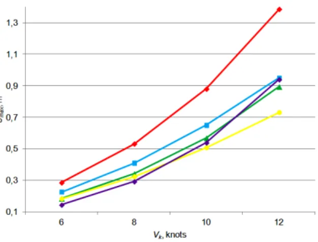
For a better observation of the difference between formulas, ship squat was calculated for other speeds: 6, 10 and 12 knots. The speed wasn’t further increased because at 14 knots, depth Froude number already exceeds the limit of 0.70. The results were compiled in Figure 4 were it can be seen that all formulas give an increasing trend for squat because it varies with speed.
Figure 4. Comparison of empirical squat formulas
Generally, Soukhomel and Zass squat has the
smallest values because the formula was designed for unrestricted channels and this is not
the case. It has similar values with ICORELS and
Millward until 10 knots. Then the differences between them are obvious and at 12 knots Millward’s formula give the biggest value of the three. These formulas are used in conditions other than those for which they were developed, so they should be given special attention.
Huuska/Guliev formula has the highest values of all and one could take them for granted because it
was designed for canal conditions, butin this case
Lpp/T ratio constraint wasn’t fulfilled, so the values
cannot be reliable.
Barrass formula overestimates ship squat and due to its simplicity is better to use it for the "concept" phase of waterways design. Moreover, using bigger squat values than real ones can be considered a precautionary measure in terms of navigation safety in shallow waters.
CONCLUSIONS
Restricted waters impose significant effects on ship navigation. Ship squat is a phenomenon that occurs every time vessels are underway but is visible when navigation conditions are restricted, like shallow and narrow waters.
111 DOI: 10.21279/1454-864X-16-I1-018
© 2015. This work is licensed under the Creative Commons Attribution-Noncommercial-Share Alike 4.0 License. certain constraints based on the field and laboratory data used in their development. It is up to the user to chose when applying these formulas as they give a range of squat values.
Squat calculations were made for an underway cargo ship with various speeds in canal conditions to see the differences between formulas. Some of these didn’t offer reliable results because they weren’t designed for
canal conditions, but those who were, gave good results. Huuska/Guliev formula gives the highest values
compared to real squat, while Barrass values are close to reality but still overestimated.
Under keel clearance for the cargo vessel exceeds 1 m for all considered formulas and speeds, except the Huuska/Guliev at 12 knots whose values cannot be reliable. For shallower depths Barrass’s formula should be considered for squat calculation, since bigger values of squat are obtained. Thus, it is taken a precautionary measure for navigation in shallow and narrow waters. In reality ship squat is smaller, but for safety of navigation it is necessary to calculate and take into account its maximum possible value.
Maximum squat determination for shallow and/or narrow waters remains an important issue for safety of navigation. Masters should know before entering such areas, where and how much the draft will increase to take actions for countering this phenomenon.
BIBLIOGRAPHY
[1] Șerban S., Katona C., Panaitescu V. N., Case study of ship to ship interaction using NTPRO 5000 navigational simulator, “Mircea cel Bătrân” Naval Academy Scientific Bulletin, Vol. XVII, 2014, Issue 2, 31-35.
[2] Zou L., Larsson L., Numerical predictions of ship-to-ship interaction in shallow water, Ocean Engineering,
vol. 72, 2013, 386 – 402.
[3] Șerban S., Toma A., The analysis of squat and underkeel clearance for different ship types in a canal,
“Mircea cel Bătrân” Naval Academy Scientific Bulletin, Vol. XV, 2013, Issue 1, 74 – 78.
[4] Delefortrie G., Vantorre M., Eloot K., Verwilligen J., Lataire E., Squat prediction in muddy navigation
areas, Ocean Engineering, vol. 37, 2010, 1464 – 1476.
[5] Briggs M. J., Ship squat predictions for ship/tow simulator, Coastal and Hydraulics Engineering Technical
Note 72, 2006.
[6] Briggs M. J., Vantorre M., Uliczka K., Prediction of Squat for Underkeel Clearance, Handbook of Coastal
and Ocean Engineering, Los Angeles, 2010, 723 – 774.
[7] Briggs M., Maynord S., Charleston Harbor Ship Motion Data Collection and Squat Analysis, US Army
Engineer Research and Development Center, Coastal and Hydraulics Engineering Technical Notes, section IX, 2004.
[8] Briggs M. J., Kopp P. J., Ankudinov V., Silver A. L., Ship Squat Comparison and Validation Using PIANC,
Ankudinov and BNT Predictions, 2nd International Conference on Ship Maneuvering in Shallow and Confined
Water: Ship to Ship Interaction, Norway, 59 – 70.

![Figure 2. Huuska/Guliev K 1 versus S [6]](https://thumb-eu.123doks.com/thumbv2/123dok_br/17223063.244052/4.893.90.420.175.546/figure-huuska-guliev-k-versus-s.webp)
![Table 3. Main dimensions of cargo ship Ship type ∆ [tdw] L pp [m] B [m] T [m] C B Cargo ship 7800 118 17.1 7.76 0.667](https://thumb-eu.123doks.com/thumbv2/123dok_br/17223063.244052/5.893.86.753.139.1161/table-main-dimensions-cargo-ship-ship-type-cargo.webp)