www.ajer.org
Research Paper Open Access
Microcontroller based new single-phase transformer less inverter
for grid-tied photovoltaic system with constant common mode
voltage
Nadia Afrin
1, Monirul Islam
2, Anarul Islam
31Dept. of EEE, Pabna University of Science and Technology(PUST),Bangladesh. 2
Dept. of EE, University of Malaya (UM), Malaysia. 3Dept. of CSE, Khulna University (KU), Bangladesh
ABSTRACT
-
Recently, transformerless inverters are becoming more attractive for grid-tied photovoltaic (PV) system because of high efficiency and low cost. Unfortunately, leakage current may flow through the whole grid-tied PV system due to fluctuating common mode (CM) voltage that depends on the topology structure and control strategy. Therefore, to meet the safety regulations, leakage current of transformerless PV inverter has to be addressed carefully. In this paper, a new microcontroller based transformerless topology with low leakage current is proposed for grid-tied PV system. A 16-bit dSPIC microcontroller is implemented to control the proposed topology. The proposed circuit structure and detail operation principle are presented in this paper. One additional switch with conventional full-bridge inverter and a diode clamping branch ensure the disconnection of PV module from the grid at the freewheeling mode and clamp the short-circuited output voltage to the half of DC input voltage. Therefore, the CM leakage current is minimized considerably. Meanwhile, MOSFET switches have been used in the proposed inverter to improve the efficiency at light-load condition. Finally, a prototype has been developed to verify the theoretical analysis and the experimental results show that the performance of the proposed inverter is as expected. It is found that the maximum efficiency and European efficiency of the proposed inverter is 98% and 97.52%, respectively.Keywords
-
Common mode voltage; Converter; Grid connected; Leakage current; Photovoltaic; Transformer less.I.
Introduction
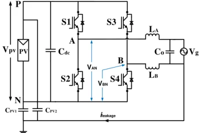
Transformerless grid-tied inverter has many advantages such as high efficiency, low cost, smaller size, and weight. However, there is a galvanic connection between the power grid and the PV module due to the omission of transformer. As a result, a resonant circuit can be formed and a high frequency voltage fluctuation between the solar array and the ground that depends on the topology structure and control strategy, can electrify this resonant circuit. Thus a leakage current iLeakage may induce due to the fluctuating CM voltage across the parasitic capacitor, flowing through the loop involving the inverter bridge, output filter, parasitic capacitors (Cpv1 and Cpv2), and the power grid [1-3]. Consequently, the grid current harmonics and total system losses are increased. A person, who touch the PV array and connected to the ground, may be conducted by the capacitive current. In the meantime, conducted and radiated interference will be brought in by the ground current [1, 4]. The instantaneous CM voltage and leakage current in the conventional full-bridge inverter shown in Figure 1 is defined as follows [5]:
1 2
C M A N B N
V V V (1)
C M P V C M
d V i
d t
c
(2)
V
gV
pvS1
S3
S2
S4
L
AL
BC
oA
B
N
P
PV
C
dcVAN
VBN
CPV1 CPV2
ileakage
Figure 1: leakage current and parasitic capacitance in transformerless grid connected PV system
(1) Bipolar sinusoidal pulse width modulated (SPWM) full-bridge inverter: Bipolar SPWM modulation can be used to address the problem of leakage current in the conventional full-bridge inverter. This inverter can keep the CM voltage constant during the whole grid period. The main drawback of this inverter is the two-level output voltage. Consequently, the current ripples across the filter inductors are increased, results large inductor size, high losses and low efficiency. As well, it is difficult to maintain a good synchronization among the gate pulses of the power switches [2].
(2) Unipolar sinusoidal pulse width modulated full-bridge inverter: Unipolar SPWM is the most popular modulation implemented in full-bridge topology, because it shows a lot of benefits in comparison to bipolar SPWM such as lower current ripple at high frequency, better efficiency, lower electromagnetic interferences emission, etc. However, when unipolar SPWM is employed to the conventional full-bridge inverter; in active mode, the CM voltage VCM is equal to 0.5Vpv but in the freewheeling mode VCM is equal to Vpv or 0 depending on the bridge-leg mid-points (point A and B in Fig. 1) coupled to the positive or negative terminal of the DC input. Therefore, the CM voltage of conventional full-bridge inverter fluctuates with high frequency which leads to high leakage current [2, 21, 22].
Vg
Vpv
S1 S3
S2 S4
LA
LB Co
Cdc2
A
B
N P
S5
PV
S6 Cdc1 D7
D8
(a)
Vg
Vpv
S1 S3
S2 S4
LA
LB A
B
N P
S5
PV Cdc1 Co
S6
Vg
Vpv
S2 S4
LB
Co
A
B
N
S5
D2 D1
D4 D3
Cdc2
PV
(c)
Vg
Vpv
S1
S2 S4
LA
LB
A
B
N P
PV C
dc
D2
S3
Co
D2
S5 S5
(d)
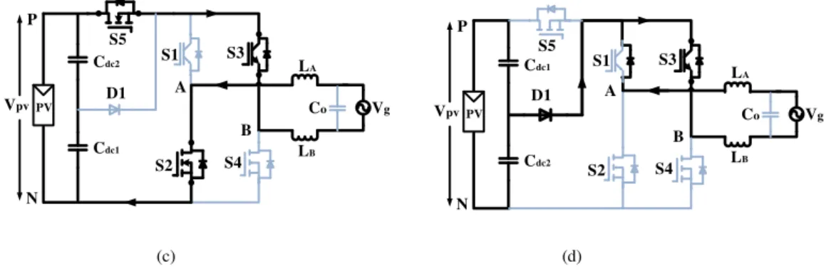
Figure 2: Some existing transformerless topologies for grid-tied PV inverter (a) H6 topology proposed in [5] (b) HERIC topology proposed in [16] (c) HB-ZVR topology proposed in [14] (d) H6 type topology proposed in [13].
In order to solve the problem of leakage current, the PV module should be separated from the grid during the freewheeling period and a lot of depth researches have been conducted from different countries. Most of the topology proposed in the literature is based on the structure of the freewheeling path, where a new freewheeling path has been created [5-18].
In this paper, a new structure of transformerless inverter for grid-tied PV system is proposed by adding an extra switch and a diode clamping branch with the conventional full-bridge inverter. The proposed inverter ensures the decoupling of PV module from the grid during the freewheeling period and the clamping of freewheeling voltage to the half of DC input voltage. As a result, the CM mode voltage is kept constant during the whole operation period and the induced leakage current is minimized to zero. In addition, unipolar SPWM can be employed to the proposed topology with three-level output voltage. The efficiency of the proposed inverter, H6 inverter and HERIC inverter are calculated and compared. Finally, a 1kW prototype is built and tested. The experimental results verify the theoretical analysis.
II.
H5 TOPOLOGY
2.1 Circuit configuration and operation principleAn explicit inverter topology proposed in [17]is called H5 topology which is shown in Figure 3. It is made up by adding an extra switch S5 with the full-bridge inverter. Unipolar SPWM has been applied to control this topology with three-level output voltage. This topology can meet the condition of eliminating CM leakage current. In the positive half cycle of grid current, switch S5 and S4 are commutated with switching frequency. During the zero voltage vectors, S5 and S4 are turned-off and freewheeling current flows through S1 and the anti-parallel diode of S3. In the negative half cycle, S5 and S2 are commutated with switching frequency and the freewheeling current flows through S3 and the anti-parallel diode of S1. A fluctuation of CM voltage can be observed with this topology because the freewheeling voltages are not clamped at the mid-point of DC input voltage. As a result, leakage current may not be fully eliminated with this topology.
Vg
Vpv
S1 S3
S2 S4
LA
LB Co
A
B
N P
S5
(a)
(b)
Figure 4: Waveform of VAN, VBN, and VCM of H5 topology: (a) simulation result (b) experimental result
2.2 CM voltage and leakage current of H5 topology
The CM voltage and the leakage current for H5 topology can be calculated using equation (3) and (4) as follows:
2
B N A N C M
V V
V (3)
C M P V C M
d V i
d t
c
(4)
Figure 4 shows the simulated and experimental waveform of CM voltage and leakage current of H5 topology. It can be seen that a fluctuation of CM voltage is presented. Since there is no clamping circuit to clamp the freewheeling voltage; as a result, a fluctuation of CM voltage and non-negligible leakage current is observed with this topology. Therefore, it is important to clamp the freewheeling path voltage to the mid-point of DC bus to keep CM voltage constant.
Vg
Vpv
S1 S3
S2 S4
LA
LB
Co
Cdc2
A
B
N P
S5
PV
D1 Cdc1
(a)
Vg
S1
iref
S2
S3
S4
S5
(b)
In order to clamp the freewheeling path voltage to the mid-point of DC bus, a unidirectional clamping branch made up by a diode and a capacitor dividor is added to the conventional H5 topology and the high-frequency IGBT switches from each phase leg are replaced by MOSFET switches which is shown in Figure 5(a). As a result, the PV module is decoupled during freewheeling period and also the CM voltage is clamped to half of DC input voltage. LA, LB, and Co constructs the LC type filter coupled to the grid. This topology can achieve three-level output voltage with unipolar SPWM.
1.2. Operation principle analysis
Grid tied photovoltaic system generally operates at unity power factor. Figure 5(b) shows the waveform of the switching pattern for the proposed topology. The operation principle of the proposed topology is very similar to the H5 topology, which is shown in Figure 6. Consequently, four operational modes are proposed that produce the output voltage states of +VPV, 0, and –VPV.
Mode 1 is the active mode in the positive half cycle of grid current. When S1, S4 and S5 are turned-on, the voltage VAN = VPV and VBN = 0, thus VAB = VPV and the CM voltage become:
1 1
0
2 2 2
P V
C M A N B N P V
V
V V V V (5)
Mode 2 is the freewheeling mode in the positive half cycle of grid current as shown in Fig. 6(b). The freewheeling current flows through S1 and body-diode of S3. In this mode, the CM voltage is clamped to the half of DC input voltage through diode D1, thus VAN = VBN = VPV/2 and VAB = 0. The CM voltage could be as follows:
1 1
2 2 2 2 2
P V P V P V
C M A N B N
V V V
V V V
(6)
Mode 3 is the active mode in the negative half cycle of grid current. Like as mode 1, when S2, S3 and S5 are turned-on, the voltage VAN = 0 and VBN = VPV, thus VAB = -VPV and the CM voltage is,
2 1 1 0 2 2 P VC M A N B N P V
V
V V V V (7)
Mode 4 is the freewheeling mode in the negative half cycle of grid current. When S5 and S2 are turned-off, the freewheeling current flows through S3 and body diode of S1 and the freewheeling path voltage is clamped to the mid-point of DC bus through D1. In this mode, VAN = VBN = VPV/2, thus VAB = 0 and the CM voltage become,
1 1
2 2 2 2 2
P V P V P V
C M A N B N
V V V
V V V
(8)
As analysis above, the CM voltage remains constant during the four commutation modes of the proposed inverter and equals to VPV/2. As a result, the inverter hardly generates any CM leakage current. However, if the freewheeling path voltage (VAN≈ VBN) is less than VPV/2, the diode D1 is forward bised and the freewheeling current flows from DC link to the freewheeling path. In contrast, if the freewheeling path voltage (VAN≈ VBN) is greater than VPV/2, the diode D1 is reverse bised. As a result, the CM voltage is not clamped at the mid-point of DC bus. Vg Vpv S1 S3 S2 S4 LA LB Co A B N P S5 PV Cdc1 Cdc2 D1 Vg Vpv S1 S3 S2 S4 LA LB Co A B N P S5 PV Cdc D1
Vg
Vpv
S1 S3
S2 S4
LA
LB
Co
A
B
N P
S5
PV
Cdc1
Cdc2
D1
Vg
Vpv
S1 S3
S2 S4
LA
LB
Co
A
B
N P
S5
PV
Cdc2
Cdc1
D1
(c) (d)
Figure 6: Operation principle of the proposed topology: (a) active mode and (b) freewheeling mode in the positive half cycle of grid current (c) active mode and (d) freewheeling mode in the negative half cycle of grid current
IV.
SIMULATION AND EXPERIMENTAL RESULTS
In order to verify the theoretical analysis, a 1kWp PV array is simulated by MATLAB/Simulink software, having the frame of panels connected to the ground with the parasitic capacitance of 75nF. As well, a 1kW proposed inverter prototype is built and tested in our laboratory. The detail components and parameters are given in Table 1.
Table 1: Specification of the prototype
Inverter Parameter Value
Input Voltage 400VDC
Grid Voltage / Frequency 230V / 50Hz
Rated Power 1000 W
AC output current 4.2A
Switching Frequency 20kHz
DC bus capacitor 470µF
Filter capacitor 2.2µF
Filter Inductor LA, LB 1mH
PV parasitic capacitor Cpv1, Cpv2 75nF
MOSFET switches IPW60R041C6
IGBT switches STGW30NC120HD
(a)
(b)
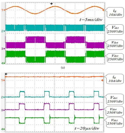
Figure 8: Drain-source voltage of the switches S2, S4, and S5 at (a) Grid cycle (b) PWM cycle
(a)
are in agreement with the theoretical analysis made in section 3 and also the gate drive voltages are kept constant at the desired level. The voltage across drain to source of the MOSFET switches is shown in Figure 8. It can be seen that under symmetric transient condition, the switching voltage across the switches is clamped to the half of input voltage. As a result, the switching losses are reduced considerably.
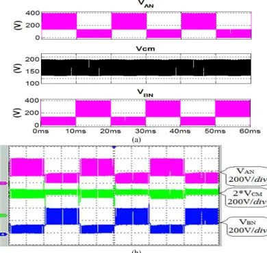
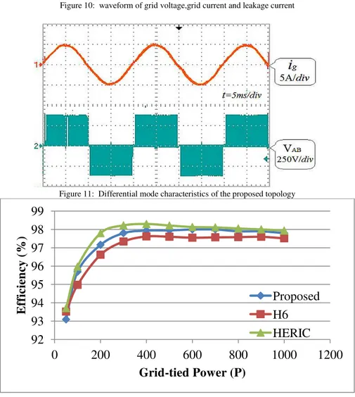
Figure 9 shows the simulated and experimental waveform of voltage VAN, VBN, and VCM. As seen in Figure 9(a), the CM mode voltage is kept constant at 200V which is the half of the DC input voltage. The experimental waveforms are similar to the simulation results which are shown in Figure 9(b). As a result, the generated leakage current is very low as shown in Figure 10. The peak value and RMS value of CM leakage current is measured less than 20mA and 8mA, respectively. These peak and RMS values are lower in magnitude corresponding to the German standard VDE0126-1-1.
Figure 10: waveform of grid voltage,grid current and leakage current
Figure 11: Differential mode characteristics of the proposed topology
Figure 12: Efficiency comparison between the proposed topology, HERIC topology and H6 topology
92
93
94
95
96
97
98
99
0
200
400
600
800
1000
1200
E
ff
icie
n
cy
(%
)
Grid-tied Power (P)
waveform of differential output voltage is shown in Figure 11. It can be seen that the proposed inverter has three-level output voltage as +VPV, 0, and -VPV. It designates that the proposed topology is modulated with unipolar SPWM having excellent
differential mode characteristics. The efficiency comparison curve of the proposed topology, HERIC topology and H6 topology are illustrated in Figure 14. Note that the presented efficiency diagram covers the total device losses and the output filter losses but it does not include the losses for the control circuit. It is clear that the efficiency of the proposed topology is higher than the H6 topology and almost same to the HERIC topology. The European efficiency of the proposed topology, H6 topology and HERIC topology are 97.51, 97.15, and 97.83 respectively, which are calculated in equation (10).
5 % 1 0 % 2 0 % 3 0 % 5 0 % 1 0 0 %
0 .0 3 0 .0 6 0 .1 3 0 .1 0 0 .4 8 0 .2
E U
(10)
V.
CONCLUSION
In this paper, a new single phase transformerless inverter for grid connected PV system is presented. The proposed inverter has some advantages as: (1) the CM voltage of the proposed topology is clamped to the half of DC input voltage; as a result, leakage current is well suppressed, (2) it can achieve three-level output voltage by employing unipolar SPWM with good differential-mode characteristics, (3) no dead time is required at grid zero crossing instant which reduces the total harmonic distortion (4) the output current shows that the proposed inverter can convert the solar power into high quality ac power which constitutes an attractive feature. The maximum efficiency and European efficiency of the proposed inverter is measured 98% and 97.8%, which make it very attractive. Therefore, it can be concluded that the proposed inverter is very suitable for single-phase grid connected PV system.
REFERENCE
[1] Z. Li, S. Kai, F. Lanlan, W. Hongfei, and X. Yan, "A Family of Neutral Point Clamped Full-Bridge Topologies for Transformerless Photovoltaic Grid-Tied Inverters," IEEE Transactions on Power Electronics, vol. 28, pp. 730-739, 2013.
[2] I. Patrao, E. Figueres, F. González-Espín, and G. Garcerá, "Transformerless topologies for grid-connected single-phase photovoltaic inverters," Renewable and Sustainable Energy Reviews, vol. 15, pp. 3423-3431, 9// 2011. [3] M. Islam, S. Mekhilef, and M. Hasan, "Single phase transformerless inverter topologies for grid-tied photovoltaic
system: A review," Renewable and Sustainable Energy Reviews, vol. 45, pp. 69-86, 2015.
[4] M. Islam and S. Mekhilef, "H6-type transformerless single-phase inverter for grid-tied photovoltaic system," IET Power Electronics, vol. 8, pp. 636-644, 2015.
[5] R. Gonzalez, J. Lopez, P. Sanchis, and L. Marroyo, "Transformerless Inverter for Single-Phase Photovoltaic Systems," IEEE Transactions on Power Electronics, vol. 22, pp. 693-697, 2007.
[6] H. Xiao, X. P. Liu, and K. Lan, "Zero-Voltage-Transition Full Bridge Topologies for Transformerless Photovoltaic Grid-Connected Inverter," IEEE Transactions on Industrial Electronics, vol. PP, pp. 1-1, 2014.
[7] S. H. Lee, K. T. Kim, J. M. Kwon, and B. H. Kwon, "Single-phase transformerless bi-directional inverter with high efficiency and low leakage current," IET Power Electronics, vol. 7, pp. 451-458, 2014.
[8] L. Zhang, K. Sun, Y. Xing, and M. Xu, "H6 Transformerless Full-Bridge PV Grid-tied Inverters," IEEE Transactions on Power Electronics, vol. PP, pp. 1-1, 2013.
[9] W. Yong and L. Rui, "Novel High-Efficiency Three-Level Stacked-Neutral-Point-Clamped Grid-Tied Inverter,"
IEEE Transactions on Industrial Electronics, vol. 60, pp. 3766-3774, 2013.
[10] G. Bin, J. Dominic, L. Jih-Sheng, C. Chien-Liang, T. LaBella, and C. Baifeng, "High Reliability and Efficiency Single-Phase Transformerless Inverter for Grid-Connected Photovoltaic Systems," IEEE Transactions on Power Electronics, vol. 28, pp. 2235-2245, 2013.
[11] J. Baojian, W. Jianhua, and Z. Jianfeng, "High-Efficiency Single-Phase Transformerless PV H6 Inverter With Hybrid Modulation Method," IEEE Transactions on Industrial Electronics, vol. 60, pp. 2104-2115, 2013.
[12] Y. Bo, L. Wuhua, G. Yunjie, C. Wenfeng, and H. Xiangning, "Improved Transformerless Inverter With Common-Mode Leakage Current Elimination for a Photovoltaic Grid-Connected Power System," IEEE Transactions on Power Electronics, vol. 27, pp. 752-762, 2012.
[13] W. Yu, J.-S. Lai, H. Qian, and C. Hutchens, "High-efficiency MOSFET inverter with H6-type configuration for photovoltaic nonisolated AC-module applications," IEEE Transactions on Power Electronics, vol. 26, pp. 1253-1260, 2011.
[14] T. Kerekes, R. Teodorescu, P. Rodriguez, G. Vazquez, and E. Aldabas, "A New High-Efficiency Single-Phase Transformerless PV Inverter Topology," IEEE Transactions on Industrial Electronics, vol. 58, pp. 184-191, 2011. [15] X. Huafeng, X. Shaojun, C. Yang, and H. Ruhai, "An Optimized Transformerless Photovoltaic Grid-Connected
Inverter," IEEE Transactions on Industrial Electronics, vol. 58, pp. 1887-1895, 2011.
[16] D. Schmidt, D. Siedle, and J. Ketterer, "Inverter for transforming a DC voltage into an AC current or an AC voltage," ed: EP Patent 1,369,985, 2009.
Zero-Crossing Distortion," International Journal of Renewable Energy Research (IJRER), vol. 2, pp. 140-146, 2012.
[19] M. Islam, S. Mekhilef, and F. M. Albatsh, "An improved transformerless grid connected photovoltaic inverter with common mode leakage current elimination," in 7th IET International Conference on Power Electronics, Machines and Drives (PEMD 2014), 2014, pp. 1-6.
[20] M. Islam and S. Mekhilef, "An improved transformerless grid connected photovoltaic inverter with reduced leakage current," Energy Conversion and Management, vol. 88, pp. 854-862, 2014.
[21] X. Huafeng and X. Shaojun, "Leakage Current Analytical Model and Application in Single-Phase Transformerless Photovoltaic Grid-Connected Inverter," IEEE Transactions on Electromagnetic Compatibility, vol. 52, pp. 902-913, 2010.
![Figure 2: Some existing transformerless topologies for grid-tied PV inverter (a) H6 topology proposed in [5] (b) HERIC topology proposed in [16] (c) HB-ZVR topology proposed in [14] (d) H6 type topology proposed in [13]](https://thumb-eu.123doks.com/thumbv2/123dok_br/17100977.237445/3.892.257.645.138.468/existing-transformerless-topologies-inverter-topology-proposed-topology-proposed.webp)