MELTING OF A PHASE CHANGE MATERIAL IN A
HORIZONTAL ANNULUS WITH DISCRETE HEAT SOURCES
by
Mohammad MASTIANIa*, Abdolrahman DADVANDb, Hooshyar MIRZAEIb, Seyed Sahand SEBTIb, and Sina KASHANIc
a Department of Ocean and Mechanical Engineering, Florida Atlantic University,
Boca Raton, Fla., USA
b Department of Mechanical Engineering, Urmia University of Technology, Urmia, Iran c Department of Mechanical Engineering, Gorgan Branch, Kordkoy Center
Islamic Azad University, Golestan, Iran
Original scientific paper DOI: 10.2298/TSCI121024094M
Phase change materials have found many industrial applications such as cooling of electronic devices and thermal energy storage. This paper investigates numer-ically the melting process of a phase change material in a 2-D horizontal annulus with different arrangements of two discrete heat sources. The sources are posi-tioned on the inner cylinder of the annulus and assumed as constant-temperature boundary conditions. The remaining portion of the inner cylinder wall as well as the outer cylinder wall is considered to be insulated. The emphasis is mainly on the effects of the arrangement of the heat source pair on the fluid flow and heat transfer features. The governing equations are solved on a non-uniform O type mesh using a pressure-based finite volume method with an enthalpy porosity technique to trace the solid and liquid interface. The results are obtained at Ra = 104 and presented in terms of streamlines, isotherms, melting phase front, liquid fraction, and dimensionless heat flux. It is observed that, depending on the arrangement of heat sources, the liquid fraction increases both linearly and non-linearlywith time but will slow down at the end of the melting process. It can also be concluded that proper arrangement of discrete heat sources has the great potential in improving the energy storage system. For instance, the arrangement C.3 where the heat sources are located on the bottom part of the inner cylinder wall can expedite the melting process as compared to the other arrangements. Key words: discrete heating, cylindrical annulus, phase change material,
thermal energy storage
Introduction
Continuous increasing of energy consumption in recent decades has led to the dra-matic depletion and scarcity of fossil fuel resources as well as a rise in global warming emis-sion. The abovementioned reasons are significant driving forces behind paying more attention to the renewable energy sources such as wind power, solar energy, and so forth as alternatives to the conventional energy sources. To achieve this goal, energy storage system as a proper option to provide reliable energy has been developed in recent years. There are three types of thermal energy storage: sensible heat, latent heat, and thermo-chemical heat. Latent heat stor-age system has received considerable attention within years because of its high energy storstor-age ––––––––––––––
density and its ability to provide heat at a constant temperature.This implies that a latent heat storage system requires a much smaller weight and volume of material to store a certain amount of energy as compared to a sensible heat storage system. Therefore, it has increasing-ly found many applications such as food storage, heating and cooling in buildings (domestic applications), and refrigerators.
By choosing the suitable storage materials known as phase change materials (PCM), large amount of heat can be absorbed or released during the melting or solidification process-es, respectively. Fundamentally, there have been numerous investigations on phase change process. Alternate melting-freezing heat transfer in composite slabs of single and composite PCM was studied by Gong and Mujumdar [1]. The numerical results indicated that using mul-tiple composite PCM greatly enhances heat flux. A comprehensive study on thermal energy storage using solid-liquid phase change was conducted by Zalba, et al. [2]. The study was structured in three parts: materials, heat transfer, and applications. Assis, et al. [3] studied ex-perimentally and numerically melting of the PCM in spherical geometry. The PCM as one of the most efficient ways of storing solar energy were studied by Kenisarin and Mahkamov [4]. They also studied the properties of various PCM and methods of heat transfer enhancement. The melting of the PCM inside a sphere using n-octadecane for both constrained and uncon-strained melting was investigated by Tan [5]. Sharma, et al. [6] investigated the available thermal energy storage technology as well as a wide range of PCM application. The con-strained melting of PCM in a spherical capsule was investigated numerically and experimen-tally by Tan, et al. [7]. Various characteristics of two mechanisms of heat transfer namely conduction and convection in different regions of the sphere were studied at different times. Ismail and Moraes [8] investigated the effects of different PCM as well as variation of the sur-face temperature, material, and diameter of the spherical and cylindrical shells on the solidifi-cation duration of PCM. Cabeza, et al. [9] presented a review of the recent publications on the use of PCM in building.
On the other hand, several researches were carried out to investigate the melting process of PCM in different types of horizontal annulus. Ng, et al. [10] simulated the con-vection-dominated melting of a PCM in a horizontal annulus heated isothermally from the inside wall using the finite element method. Melting of a pure PCM in a horizontal annulus of arbitrary cross-section was studied numerically by Khillarkar, et al. [11]. Numerical study of melting inside concentric and eccentric horizontal cylindrical annuli was conducted by Darzi, et al. [12].
Cylindrical annulus containing a fluid with discrete heat sources has increasingly found many engineering applications such as nuclear reactors, thermal energy storage, cooling of microelectronic equipments, and food storage to name a few. Discrete heat sources play an important role in the flow field structure and heat transfer characteristics. Heat transfer en-hancement can be controlled by the size, arrangement, strength and location of the discrete heat sources.
2-D square cavity with two and three discrete heat source-sink pairs was carried out by Deng [15]. Kadiyala and Chattopadhyay [16] optimized the location of three heat sources on the vertical wall of a square cavity with natural convection using genetic algorithms combined with artificial neural networks. Natural convection in a square enclosure with a non-uniform (linearly varying temperature) isothermal heat source located at the center of the bottom wall was numerically studied by Saravanan and Sivaraj [17]. Some engineering applications in-volve all the mechanisms of heat transfer, i. e., convection, conduction and radiation simulta-neously. In such cases, it is necessary to consider the conjugate heat transfer to accurately analyze their thermo-fluid characteristics [18-21]. The convection heat transfer in a porous cavity with discrete heat sources has attracted a great deal of attention from researchers due to its wide range of applications [22-25].
Although most of the previous works on the natural convection heat transfer induced by discrete heat sources have been restricted to particular geometries such as square and rec-tangular cavities, very few is, nonetheless, available on the natural convection in cylindrical annulus using discrete heat sources [26, 27]. Beside, to the best of our knowledge, no attempt has been made as yet to study the effects of different arrangements of discrete heat sources on the melting characteristics to explore the conditions for heat transfer enhancement in a hori-zontal cylindrical annulus. The objective of this paper is to investigate numerically the melt-ing process of a PCM and the ensumelt-ing flow filed structure in a 2-D horizontal cylindrical an-nulus with various arrangements of two discrete heat sources. Particular attention is paid to finding the best arrangements of discrete heat sources from the viewpoint of heat transfer en-hancement, hence accelerating the melting process.
Mathematical formulation
The schematic of the enclosure configuration as well as the co-ordinate system em-ployed in the present study is shown in fig. 1(a). The physical model under consideration is the melting of paraffin in a 2-D horizontal cylindrical enclosure with the radius ratio ro/ri of 3,
where ro and ri are the radii of the inner and outer cylinders, respectively. The constant
tem-perature heat sources are placed on the inner cylinder. The sources are considered as π/4 rad i-ant circular arcs.
Governing equations
The flow is considered unsteady, laminar, and incompressible. As shown in tab. 1, all the thermo-physical properties of the fluid are assumed constant, except the density varia-tion in the buoyancy term, which is modeled by the Boussinesq approximavaria-tion.
Table 1. Thermophysical properties of PCM
The governing equations including conservation of mass, momentum, and energy are:
( ) ( )
0
u v
t x y
ρ ρ ρ
∂ +∂ +∂ =
∂ ∂ ∂ (1)
PCM ρ
[kgm–3] μ [Pa·s]
cp
[Jkg–1 K–1]
k [Wm–1K–1]
α [m2s–1]
β [K–1]
L
[Jkg–1] Pr
Fusion point [°C]
2
( ) ( ) ( )
x
u u uv p u u
S
t x y x x x y y
ρ ρ ρ µ µ
∂ +∂ +∂ =−∂ + ∂ ∂ + ∂ ∂ +
∂ ∂ ∂ ∂ ∂ ∂ ∂ ∂ (2)
(
)
2
( ) ( ) ( )
m y
v uv v p v v
g T T S
t x y y x x y y
ρ ρ ρ
µ µ ρ β
∂ +∂ +∂ =−∂ + ∂ ∂ + ∂ ∂ + − +
∂ ∂ ∂ ∂ ∂ ∂ ∂ ∂ (3)
( ) ( ) ( )
h
h uh vh T T
k k S
t x y x x y y
ρ ρ ρ
∂ +∂ +∂ =∂ ∂ + ∂ ∂ −
∂ ∂ ∂ ∂ ∂ ∂ ∂ (4)
In the energy eq. (4), h is the specific enthalpy, which is the sum of sensible enthal-py:
ref
s ref pd T
T
h =h +
∫
c T (5)and the latent enthalpy (heat):
L L
h =f (6)
The latent heat fL in eq. (6) varies between zero for solid and L for liquid. Therefore, f is:
s l s l s l s 0 1 T T T T
f T T T
T T
T T
<
−
= < < −
>
(7)
The source terms in the momentum and energy eqs. (2)-(4) are expressed:
2 2
x 3 y 3 h
(1 ) (1 ) [ ( )]
, ,
C f C f L f
S u S v S
t f f ρ ε ε − − ∂ = = =− ∂
+ + (8)
where the term C(1 – f)2/(f 3 + ε) is used to ensure gradual decrease in the velocities from a fi-nite value in the liquid to zero in full solid in the computational cells, which are changing phase. Here, ε is a small constant used to avoid division by zero, and C is a constant, which reflects the morphology of the melting front. In the present study, ε and C are set equal to 10–3 and 106, respectively.
The results of the present study are expressed in terms of non-dimensional numbers and parameters defined:
*
3 *
* *
h m o i m i
*
h m o i
0
( )(
Ra ) , Nu , ,
r
g T T r r T T T r r
T r
T T r r
r β νa = − − ∂ − − = =− = = − − ∂
In addition, the stream function is used to represent the flow field, which is defined:
,
u v
y x
y y
∂ = −∂ =
Boundary conditions
The no-slip boundary condition is enforced on the walls of the annulus. In addition, the temperature of the sources on the inner cylinder is kept constant at above the melting point of the PCM, whereas the outer cylinder as well as the remaining parts of the inner cylinder is assumed to be thermally insulated, i. e.:
h
on the sources
elsewhe e0 r T T
T r
= ∂ =
∂
The difference between the sources temperature and the PCM melting point is 5 °C.
Numerical procedure
A FORTRAN code was developed to solve the governing equations using the finite volume method. The SIMPLE algorithm has been applied for the velocity-pressure coupling. The discretized equations have been solved using the strongly implicit procedure. The enthal-py-porosity approach [28, 29] is applied to simulate the melting process of the PCM in the annulus. In this method, the porosity in each cell is set equal to the liquid fraction in the cell. The liquid fraction is computed at each iteration using the enthalpy balance. Due to the steep gradient of the flow properties near the annulus walls, finer grids have to be used in those re-gions to obtain accurate numerical solutions. Therefore, the grid becomes finer towards the inner and outer walls of the enclosure (see fig. 1b). It may be noted that, the grid independent tests have been performed (not shown) and nominally a grid size of 144 × 72 was adopted in all the simulations carried out in the present work.
Figure 1. (a) Physical configuration and co-ordinate system; (b) typical computational grid
Validation of the numerical procedure
as with the numerical results from Brent, et al. [31]. Figure 2(a) depicts the comparison. In this case, the top and bottom walls are as-sumed to be thermally insulated and the right and left walls are kept at constant low (cool-ing) and high (heat(cool-ing) temperatures, respec-tively. As it is clear from the fig. 2, there is an acceptable agreement between the results of the present work and those found in [30] and [31]. Likewise, the results of natural convec-tion in an annulus between horizontal concen-tric cylinders obtained from the present code are compared with the experimental results of Kuehn and Goldstein [32]. Figure 2(b) shows this comparison where the variation of the non-dimensional temperature, T*, has been depicted against the variation of non-dimensional radial distance, r*. It should be noted that, these results have been obtained for Ra = 4.7 · 104, Pr = 0.706 and the same radius ratio as used in [32]. Again, a reasona-ble agreement is found between the results of the current simulation and the experimental results found in [32]. These two comparisons reveal the accuracy of the present code.
Results and discussion
In the present work, the melting process of a PCM in a horizontal annulus is investi-gated numerically. The inner wall of the annu-lus is partially heated by a pair of heat sources located symmetrically with respect to the ver-tical axis (see fig. 3). In addition, the Rayleigh number is set equal to 104 in all the simula-tions carried out in the present study.
Figure 4 illustrates the contours of tran-sient melting phase front for all arrangements of the heat sources (see fig. 3) at various times of 100, 500, 2000, and 6000 seconds. It sho-uld be mentioned that the red and blue colors observed in fig. 4, indicate respectively the liquid and solid phases. It can be seen from fig. 4 that, at the beginning of the melting pro-cess, the solid PCM is melted near the heat sources and a symmetric thin layer of liquid is formed around the heat sources for all arrangements. Heat conduction occurs between heat sources and the cold solid PCM. The sizes of liquid zones are approximately the same in all the seven arrangements. As time progresses further, the shape of liquid zone differs from one Figure 2. (a) Melting phase front progression
with time: comparison of the present results with the results of Gau and Viskant [30] and Brent [31]; (b) Comparison of the present results (solid lines) with the experimental data (symbols) from [32]
Figure 4. Melting phase front at various times (for color image see journal web-site)
(see the last column in fig. 4). According to the last column in fig. 4, the predicted results show an unstable and complicated structure at later times that brings about the formation of waviness on the solid-liquid interface.
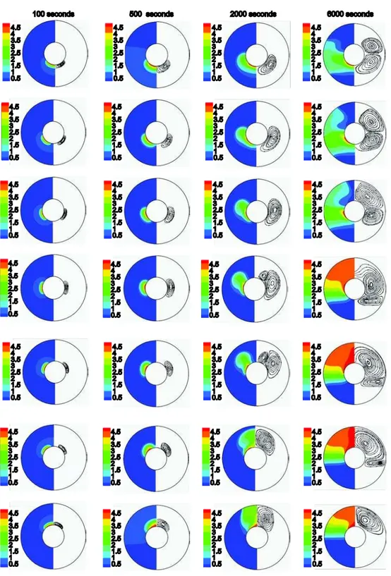
Figure 5 depicts the streamlines and isotherms shown, respectively, in the right and left halves of the annulus for different times ranging from 100 to 6000 seconds. For any ar-rangement of the heat sources, a particular flow structure is formed, which in turn determines the thermal behavior of the system. It is evident that the patterns of the isotherms and stream-lines will change with time. In addition, since the temperature of the heat sources is higher than the melting temperature, the PCM starts melting from parts of it located near the heat sources. At the beginning of the melting process, the heat conduction regime prevails due mainly to the restrictions on the liquid flow. This can be deduced from the isotherms being concentric parallel curves. A single clockwise vortex is formed close to each heat source, which moves towards the outer wall of the annulus as time increases. The melting front will increasingly penetrate the solid part of the PCM leading to a bigger vortex and consequently a wider melting region formation. The arrangement of the heat sources on the inner cylinder has significant effect on both the flow and thermal fields and consequently on the melting rate. When time increases to 6000 seconds, in the cases where the heat sources are located at the lower section of the cavity, the main vortex splits into two smaller ones having opposite direc-tions. The vortex remains single, however, if the heat sources are located at the upper section of the annulus. As time increases, the interface moves from the inner cylinder towards the outer cylinder and consequently the liquid phase occupies a major part of the cavity. This would expedite the advection in the liquid phase and hence the melting process. As may be expected, parts of the liquid-solid interface located near the sources develop faster than the rest of the interface. After a (relatively) long time, thermal stratification will occur and the isotherms become unparalleled (or distorted). Under such conditions, the convection mode becomes more dominant and thermal boundary layer develops near the inner cylinder. The presence of the free convection leads to non-planer melting front and to an increase in the melting rate. Far enough from the inner cylinder (i. e., in the central region of the cavity), the flow would not much affected by thermal boundary layers and hence the temperature gradient would not be so intensive there.
It should be mentioned that as the melting area increases, say from 2000 seconds onwards (fig. 5), the recirculation regions become greater and/or (in some arrays) increase to more than one, which affect the temperature distribution in the melting area. This phenome-non can be clearly observed in fig. 5. The natural convection of the liquid phase in arrays C.4 to C.7 (fig. 5), where the heat sources have been located at the lower part of the inner cylinder is stronger than the its counterpart in the other arrays. This leads to the stronger ascending of hot liquid and descending of cold liquid in these arrays. Thus the temperature in the upper part of the liquid phase becomes higher than that in the lower part, and the melting process is ac-celerated in the upper part.
and a relatively lower heat is transferred to the other regions. In this case, the dimensionless heat flux reaches its maximum value near the sources. As the depth of the melting region in-creases and the vortex develops further in the flow flied, the temperature gradient dein-creases, but the thermal boundary layer thickness increases. Therefore, the thermal resistance across the liquid layer increases resulting in a decrease in the dimensionless heat flux.
Figure 6. Dimensionless heat flux distribution along discrete heat sources at different times
heat transfer results in linear change of melting rate in ar-rays C.1-C.3. In addition, the variation of the liquid frac-tion with respect to time states implicitly the influence of the flow filed structure on the melting rate. At time t = 6000 seconds the volume of melted PCM in the array C.3 is slightly greater than that of the other arrays.
In other words, the highest liquid fraction and melt penetration depth are associated with the case C.3. The flow structure related to this case (see fig. 5) shows that as time increases the single vortex is divided into two vortices with opposite directions, which are symmetric with respect to the horizontal line. This would result in a greater circu-lation velocity and consequently more intensive buoyancy forces and leads to stronger penetration of the thermal filed inside the annulus. For this case the initial high value of
the dimensionless heat flux will be preserved during the melting process. Thus, this arrange-ment can be considered as the best choice from the viewpoint of melting process. In the cases C.6 and C.7 a (main) single vortex forms and remains as single throughout the melting process, while in the other cases the initial single vortices are broken. In these two cases since the vortex has been confined in the upper section of the annulus, which can be deduced from both the as-sociated streamlines and liquid fraction diagrams, the smallest melt penetration depths are ob-served. In the case C.1, the vortex is confined between the solid zone and the bottom section of the annulus and again we observe a small value of liquid fraction and a weaker melt penetration. In such cases, the dimensionless heat flux experiences a sharp increase and a rapid decrease re-spectively at the beginning and in the middle of the melting process.
Conclusions
In this paper, a numerical investigation is conducted to study the melting process of a PCM in a 2-D horizontal cylindrical annulus. The effects of different arrangements of two discrete heat sources located on the inner cylinder are studied using a pressure-based finite volume method along with an enthalpy porosity technique. The flow field features as well as the shape of phase front depend on the liquid layer thickness during the progress of the melt-ing process. It is found that at the beginnmelt-ing of the meltmelt-ing process, the heat conduction re-gime prevails due mainly to the restrictions on the liquid flow. This can be deduced from the isotherms being concentric parallel curves. Then the buoyancy-driven convection is strength-ened due to the growth of the melt zone and it is observed that in all arrays except arrays C.1 and C.2 (where the heat sources locate at the bottom part of the inner cylinder wall) the melt-ing in the top region of the annulus is much faster than in the bottom region. In addition, de-pending on the arrangement of the heat sources, the liquid fraction increases both linearly and non-linearly but will slow down at the end of the melting process. Finally, it can be concluded that using proper arrangement of discrete heat sources has the great potential to improve the energy storage system. For instance, the arrangement C.3 can be considered as the best choice from the viewpoint of the melting process.
Nomenclature C – constant
cp – specific heat at constant pressure, [Jkg–1K–1]
f – liquid fraction
g – gravitational acceleration, [ms–2]
Figure 7. Liquid fraction distribution vs. time for
h – enthalpy, [Jkg–1]
k – thermal conductivity, [Wm–1K–1]
L – latent heat, [Jkg–1] Nu – Nusselt number Pr – Prandtl number
p – pressure, [Pa]
r – radial co-ordinate, [m]
r* – dimensionless radial co-ordinate Ra – Rayleigh number
S – source term
T – temperature, [K]
T* – dimensionless temperature
t – time, [s]
u – velocity component in x direction, [ms–1]
v – velocity component in y direction, [ms–1]
x – horizontal co-ordinate, [m]
y – vertical co-ordinate, [m]
Greek symbols
α – thermal diffusivity, [m2s–1]
β – thermal expansion coefficient, [K–1] ε – constant
θ – angle, [Rad] ρ – fluid density, [kgm–3] μ – dynamic viscosity, [Nsm–2] ψ – stream function
Subscripts
h – enthalpy i – inner wall L – latent l – liquid m – melting o – outer wall ref – reference state s – solid, specific x – along x-axis y – along y-axis
References
[1] Gong, Z. X., Mujumdar, A. S., Enhancement of Energy Charge-Discharge Rates in Composite Slabs of Different Phase Change Materials, International Journal of Heat and Mass Transfer, 39 (1995), 4, pp. 725-733
[2] Zalba, B., et al., Review on Thermal Energy Storage with Phase Change: Materials, Heat Transfer Anal-ysis and Applications, Applied Thermal Engineering, 23 (2003), 3, pp. 251-283
[3] Assis, E., et al., Numerical and Experimental Study of Melting in a Spherical Shell, International Jour-nal of Heat and Mass Transfer, 50 (2007), 9-10, pp. 1790-1804
[4] Kenisarin, M., Mahkamov, K., Solar Energy Storage Using Phase Change Materials, Renewable & Sus-tainable Energy Reviews, 11 (2007), 9, pp. 1913-1965
[5] Tan, F. L., Constrained and Unconstrained Melting inside a Sphere, International Communication in Heat and Mass Transfer, 35 (2008), 4, pp. 466-475
[6] Sharma, A., et al., Review on Thermal Energy Storage with Phase Change Materials and Applications,
Renewable and Sustainable Energy Reviews,13 (2009), 12, pp. 318-345
[7] Tan, F. L., et al., Experimental and Computational Study of Constrained Melting of Phase Change Mate-rials (PCM) inside a Spherical Capsule, International Journal of Heat and Mass Transfer, 52 (2009), 15-16, pp. 3464-3472
[8] Ismail, K. A. R., Moraes, R. I. R., A Numerical and Experimental Investigation of Different Containers and PCM Options for Cold Storage Modular Units for Domestic Applications, International Journal of Heat and Mass Transfer, 52 (2009), 19-20, pp. 4195-4202
[9] Cabeza, L. F., et al., Materials Used as PCM in Thermal Energy Storage in Buildings: A Review, Re-newable and Sustainable Energy Reviews, 15 (2011), 3, pp. 1675-1695
[10]Ng, K. W., et al., Heat Transfer in Free Convection-Dominated Melting of a Phase Change Material in a Horizontal Annulus, International Communications in Heat and Mass Transfer, 25 (1998), 5, pp. 631-640
[11]Khillarkar, D. B., et al., Melting of a Phase Change Material in Concentric Horizontal Annuli of Arbi-trary Cross-Section, Applied Thermal Engineering, 20 (2000), 10, pp. 893-912
[12]Darzi, A. R., et al., Numerical Study of Melting inside Concentric and Eccentric Horizontal Annulus,
Applied Mathematical Modelling, 36 (2012), 9, pp. 4080-4086
[13]Chu, H. H. S., et al., The Effect of Heater Size, Location, Aspect Ratio, and Boundary Conditions on Two-Dimensional, Laminar, Natural Convection in Rectangular Channels, Journal of Heat Transfer, 98
(1976), 2, pp. 194-201
[15]Deng, Q.-H., Fluid Flow and Heat Transfer Characteristics of Natural Convection in Square Cavities due to Discrete Source-Sink Pairs, International Journal of Heat and Mass Transfer, 51 (2008), 25-26, pp. 5949-5957
[16]Kadiyala, P. K., Chattopadhyay, H., Optimal Location of Three Heat Sources on the Wall of a Square Cavity Using Genetic Algorithms Integrated with Artificial Neural Networks, International communica-tion in Heat and Mass Transfer, 38 (2011), 5, pp. 620-624
[17]Saravanan, S., Sivaraj, C., Natural Convection in an Enclosure with a Localized Nonuniform Heat Source on the Bottom Wall, International Journal of Heat and Mass Transfer,54 (2011), 13-14, pp. 2820-2828
[18]Muftuoglu, A., Bilgen, E., Conjugate Heat Transfer in Open Cavities with a Discrete Heater at Its Opti-mized Position, International Journal of Heat and Mass Transfer, 51 (2008), 3-4, pp. 779-788
[19]Sharma, A. K., et al., Turbulent Natural Convection of Sodium in a Cylindrical Enclosure with Multiple Internal Heat Sources: A Conjugate Heat Transfer Study, International Journal of Heat and Mass Trans-fer, 52 (2009), 11-12, pp. 2858-2870
[20]Zhang, W., et al., Conjugate Conduction-Natural Convection in an Enclosure with Time-Periodic Side-wall Temperature and Inclination, International Journal of Heat and Fluid Flow, 32 (2011), 1, pp. 52-64 [21]Kuznetsov, G. V., Sheremet, M. A., Conjugate Natural Convection in an Enclosure with a Heat Source
of Constant Heat Transfer Rate, International Journal of Heat and Mass Transfer, 54 (2011), 1-3, pp. 260-268
[22]Varol, Y., et al., Estimation of Thermal and Flow Fields due to Natural Convection Using Support Vec-tor Machines (SVM) in a Porous Cavity with Discrete Heat Sources, International Communication in Heat and Mass Transfer, 35 (2008), 8, pp. 928-936
[23]Kaluri, R. S., Basak, T., Heatline Analysis of Thermal Mixing due to Natural Convection in Discretely Heated Porous Cavities Filled with Various Fluids, Chemical Engineering Science, 65 (2010), 6, pp. 2132-2152
[24]Basak, T., et al., Analysis of Heatlines for Natural Convection within Porous Trapezoidal Enclosures: Effect of Uniform and Non-Uniform Heating of Bottom Wall, International Journal of Heat and Mass Transfer, 53 (2010), 25-26, pp. 5947-5961
[25]Kaluri, R. S. Basak, T., Role of Entropy Generation on Thermal Management during Natural Convection in Porous Square Cavities with Distributed Heat Sources, Chemical Engineering Science, 66 (2011), 10, pp. 2124-2140
[26]Sankar, M., Do, Y., Numerical Simulation of Free Convection Heat Transfer in a Vertical Annular Cavi-ty with Discrete Heating, International Communication in Heat and Mass Transfer, 37 (2010), 6, pp. 600-606
[27]Sankar, M., et al., Numerical Study of Natural Convection in a Vertical Porous Annulus Discrete Heat-ing, International Journal of Heat and Mass Transfer, 54 (2011), 7-8, pp. 1493-1505
[28]Voller, V. R., Prakash, C., A Fixed-Grid Numerical Modeling Methodology for Convection-Diffusion Mushy Region Phase-Change Problems, International Journal of Heat and Mass Transfer, 30 (1987), 8, pp. 1709-1719
[29]Dutta, R., et al., Experimental and Numerical Study of Heat Transfer in Horizontal Concentric Annulus Containing Phase Change Material, Can. J. Chem. Eng.,86 (2008), 4, pp. 700-710
[30]Gau, C., Viskanta, R., Melting and Solidification of a Pure Metal on a Vertical Wall, Journal of Heat Transfer, 108 (1986), 1, pp. 174-181
[31]Brent, A. D., et al., Enthalpy-Porosity Technique for Modeling Convection-Diffusion Phase Change: Application to the Melting of a Pure Metal, Numerical Heat Transfer, 13 (1988), 3, pp. 297-318
[32]Kuehn, T. H., Goldstein, R. J., An Experimental and Theoretical Study of Natural Convection in the An-nulus Between Horizontal Concentric Cylinders, Journal of Fluid Mechanics, 74 (1976), 4, pp. 695-719