Comparison Study of Different Lossy Compression
Techniques Applied on Digital Mammogram Images
Ayman AbuBaker*
Electrical and Computer Eng. Dept. Applied Science Private UniversityAmman, Jordan
Mohammed
Eshtay
Faculty of Information Technology Applied Science Private UniversityAmman, Jordan
Maryam AkhoZahia
Electrical and Computer Eng. Dept. Applied Science Private UniversityAmman, Jordan
Abstract—The huge growth of the usage of internet increases the need to transfer and save multimedia files. Mammogram images are part of these files that have large image size with high resolution. The compression of these images is used to reduce the size of the files without degrading the quality especially the suspicious regions in the mammogram images. Reduction of the size of these images gives more chance to store more images and minimize the cost of transmission in the case of exchanging information between radiologists. Many techniques exists in the literature to solve the loss of information in images. In this paper, two types of compression transformations are used which are Singular Value Decomposition (SVD) that transforms the image into series of Eigen vectors that depends on the dimensions of the image and Discrete Cosine Transform (DCT) that covert the image from spatial domain into frequency domain. In this paper, the Computer Aided Diagnosis (CAD) system is implemented to evaluate the microcalcification appearance in mammogram images after using the two transformation compressions. The performance of both transformations SVD and DCT is subjectively compared by a radiologist. As a result, the DCT algorithm can effectively reduce the size of the mammogram images by 65% with high quality microcalcification appearance regions.
Keywords—Mammogram Images; DCT Compression; SVD compression; Microcalcifications
I. INTRODUCTION
The emergence of internet and the vast development of web technologies in addition to the popularity of social networks, image sharing and video application triggered the inevitable need for minimizing the amount of digital information stored and transmitted. The size of images is increasing with the advancement in digital cameras and the more availability of storage devices. Hence as the size increases, more storage we need for storing these files and the higher bandwidth we need for transmission [1]. Suppose we have a color image of 3200 pixel width and 2500 pixel height, the color image usually has three components for each picture, red, green and blue (RGB). The size of such an image will be 22.9 MB.
The solution for these challenges is to apply compression to minimize the size needed for storage and transmission of such images taking into account keeping the image with good quality [2,3].The aim of the compression techniques is to reduce the redundancy and the irrelevant data. Many techniques used to compress images, predictive coding uses the decorrelation between the pixels of the image to eliminate or reduce redundancy. Huffman codding is an example of such a
technique where we give variable length coding for redundant data depending on statistical information. Wavelet transform is another type of compression techniques that deals with the image as a series of wavelets. Wavelet transforms separate signals into wavelets and then it uses the coefficients for compression by discarding some of these coefficients that will not cause big effect on the quality of the image. Wavelet transforms are very useful for compression because it reveals the fine details of the signal [1,4]. JPEG uses the discrete cosine transform (DCT) which is one of the most popular techniques used for image compression. Another technique uses the linear approximation of matrices for compression is singular value decomposition (SVD) [4].
Moreover, using the image compression techniques in medical image is crucial since it relates directly to the human life. The digital mammogram image is one of the medical images that varies in the size between 8 MB and 55 MB. Also, many studies indicated that the detection accuracy may decreased of microcalcifications tumors by radiologists if the images are digitized less that at 0.1 mm x 0.1 mm. Therefore, the mammogram images need to be reduced using compression techniques that minimize the required storage as well as maintain the microcalcification clear for the radiologist.
This paper will evaluate the performance of two compression techniques: full frame discrete cosine transform (DCT) with entropy coding and singular value decomposition (SVD) on digital mammogram images. The dependence of their efficiency on the compression parameters was investigated. The techniques are compared in terms of the trade-off between the bit rate and the detection accuracy of subtle microcalcifications by a specialist radiologist.
The remainder of this paper is organized as follows. Section II reviews some basic preliminaries like Singular Value Decomposition (SVD) and Discrete Cosine Transform (DCT), In Section III, literature review is visited. The implementation of SVD and DCT on mammograms images is presented in section IV. Experiments and evaluation of the results have been presented in Section V. Section VI concludes the work with some future directions.
II. THEORETICAL BACKGROUND
The objective of image compression is reducing or eliminating irrelevant and redundant data to efficiently store and transmit images. The sources of redundancy can be divided into the following three categories [2].
1) Coding redundancy: Huffman coding is a famous example of coding redundancy. The idea is to assign variable length codes to combinations depending on the frequency of appearances of these combinations in the original data. Statistical approach is used to bind the appropriate combination with the appropriate code [1].
2) Spatial redundancy: Spatial redundancy is term that describes the elements that are duplicated in the structure. In digital images the neighboring pixels are usually similar, one of the techniques that uses this type is constant area encoding [1].
3) Irrelevant data: Many of the information existed in 2D arrays that represent images are ignored by the human vision systems. The idea is to discard the data that is less important and hardly noticed by the human. Human eye is less sensitive to higher level frequencies. Many of the compression techniques use this property to eliminate or reduce redundancies of such type of information. Discrete cosine transform is a well-known technique of this type [1].
The compression techniques are usually classified into two major categories: lossless and lossy techniques. Lossless algorithms preserve the same information so we can get the original data anytime and they are actually exploits the data redundancy in the original data. Examples of lossless techniques are Huffman, run length encoding and Lempel-Ziv-Welch (LZW) Coding. Lossy algorithms do not retain the original so they are called irreversible. Lossy algorithms exploit both data redundancy and human perception properties. As a result of eliminating part of information we can get higher compression rates using lossy techniques [5].
A. Singular Value Decomposition (SVD)
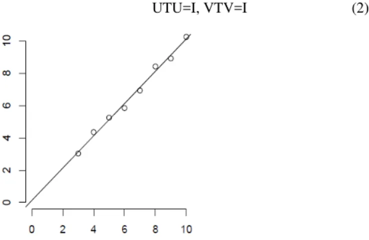
SVD can be viewed through three different points of view: the first one is that SVD is a method to transform set of correlated variable into set of uncorrelated variables that describes the relationships between the data items. The second point of view sees SVD as a method to specify the dimensions in which the data items represent high variations. The third one is that as we recognize the biggest variation of data we can reach the best approximation using fewer dimensions Fig. 1[8]. The main idea of SVD is taking high data set dimensions and reduces it to fewer dimensions with retaining the original substructure of the data. The main reason behind using SVD in compression is that we can work with it as a method for data reduction.
In linear algebra SVD is a way to compose matrix into series of linear approximations. SVD factorize the matrix into product of matrices [9]. So, SVD of matrix M is a factorization of the form as in (1):
(1) Where is a diagonal matrix that only contains the diagonal entries i. i of are called the singular values of M. The columns of U are called the left-singular vectors of M and
the columns of V are called the right-singular vectors of M [8] as in (2).
UTU=I, VTV=I (2)
Fig. 1. SVD reduce data from two dimensions to one dimension
Each column in U is one of the orthonormal eigenvectors of , and each column of V is one of the orthonormal eigenvectors of . The singular values of M are the square roots of eigenvalues of U or V in descending order.
Applying SVD decompose the image into three matrices but doing this only does not compress the image actually. To perform the compression we need only to retain few number of singular values of the diagonal matrix [9].
Since the singular values then the first value of the diagonal matrix has the biggest impact on the total sum, followed by the second value and so on. Thus the singular values in the bottom of the list contain negligible value and can be discarded for the sake of compression.
The approximation is performed by taking only the first few terms of the diagonal matrix as shown in (3).
∑ (3) As k increases the image quality increase but also the needed memory of storage is also increased.
B. Discrete Cosine Transform (DCT)
The DCT works by transforming image from spatial representation into frequency domain. The image is separated into parts of differing frequencies. Image is represented as a sum of sinusoids of varying magnitude and frequencies. DCT is high energy compact so the most significant image information is concentrated in few coefficient of DCT [5].
The less important frequencies are discarded hence the lossy compression. The only important frequencies are used to retrieve the image in the decompression process.
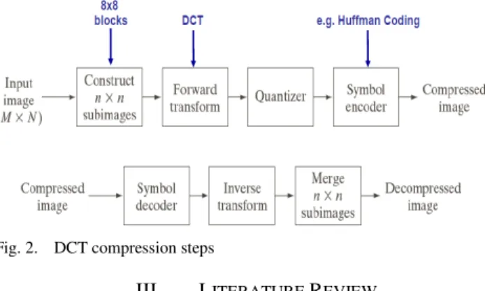
The steps of DCT compression that shown in Fig.2 are summarized as follows:
4) Input image (MxN).
5) Initiate subimages blocks (8x8).
6) Apply DCT on each block.
7) Quantization process.
The step of quantization will normalize the resultant matrix taking into account the psycho visual properties. Selecting of the quantization matrix has effect on the compression ratio.
One of the most attractive properties of DCT is that it preserves the most information of the image in fewest coefficients [7].
Fig. 2. DCT compression steps
III. LITERATURE REVIEW
Image size reduction is a critical stage in many image processing systems for applications such as mammography, multimedia and electronic publishing [14, 27]. Many techniques are available to magnify or reduce images ranging from linear interpolation to cubic spline interpolation [10, 19, 20, 26].
Image interpolation has a central role in many applications [27, 24]. One was changing the size of a digital image according to the nature of the display device. According to Chuah and Leou [12], three categories exist for image interpolation: static image interpolation [13, 23], multi-frame image interpolation [11, 26], and image sequence (video) interpolation [11].
One of the simplest techniques for image interpolation is the nearest neighbor pixel. In this approach, the intensity of every pixel in the resultant image is set equal to the intensity of its nearest corresponding pixel in the original image. This method is extremely simple to implement but tends to produce images with a clustered or blocky appearance due to the low interpolation order. Bi-linear interpolation is another interpolation technique that uses the weighted average value of the four pixels nearest the exact position of a pixel in the source image corresponding to a pixel in the final image [21, 24]. However, small points in high resolution images, such as mammogram images, will be eliminated by this bi-linear interpolation since interpolation using 4 neighbor pixels was not enough for small or so hazy points. Another interesting interpolation method is the bi-cubic interpolation technique. Bi-cubic interpolation is a sophisticated technique that produces smoother edges than bi-linear interpolation [16]. This method combines better effectiveness and lower complexity compared to other interpolation techniques [21]. In mammogram images there are no abrupt changes between the neighboring pixels. Therefore, using bi-cubic interpolation will generate a representative pixel from 16 neighboring pixels that will facilitate scaling down mammogram images. Herasa et al. [17] compared the visual appearance of three interpolation methods linear, bi-cubic and the parametric spline method,
which was a compromise between the previous two methods. They build a robust algorithm OPED for the reconstruction of images from Radon data using these interpolation methods. The bi-cubic interpolation showed a good performance with a significantly lower Normalized Mean Square Error (NMSE) than the other methods.
Other algorithms have been developed with modified interpolation processes. Kim et al. [16] proposed a new image scaling algorithm called the Winscale algorithm. The scaling (up/down) in this algorithm was based on the use of an area pixel model rather than a point pixel model. As a result, the Winscale algorithm produced effective results for image processing systems that required high visual quality and low computational complexity. However, its performance was similar to the bi-linear interpolation technique [15]. An adaptive algorithm was proposed by Chuah and Leou [12] to interpolate low resolution (decimated) image frames. In this algorithm, two nonlinear filters were used to generate high-frequency components iteratively that were lost during the implementation of the resolution reduction procedure, then a blocking artefacts-reduction scheme was adopted to improve the image quality. Abe and Iiguni [25] investigated the discrete cosine transform (DCT) in down-sampled images and proposed high-resolution (HR) image restoration from a down-sampled low-resolution (LR) image using the discrete cosine transform (DCT). Their algorithm showed a superior performance compared to cubic spline interpolation in the HR image restoration as long as the amount of the additive noise was small.
Many reduction techniques were based on image interpolation that was followed by a re-sampling process. These techniques were simple to implement but produce sub-optimal results [20]. Another technique used in image reduction utilizes the mean of each non-overlapping 8×8 pixel neighbourhood [18]. This blurred the breast boundary since the boundary was averaged with the background. As a result, an important breast regions such as microcalcification are lost which means that there are a significant loss of the information in the original mammogram images.
IV. THE ALGORITHM IMPLEMENTATION
Mammogram images show abnormal structures inside a breast, and one of the important breast tumors is microcalcification (MC). Since microcalcifications are small (less than 1mm across [26]), there is a necessity for high resolution images in order to show MCs clearly in the mammogram images. Therefore, mammogram images are high-resolution and large size images that require specialized computing capabilities to process. Moreover, transmitting these images over computer networks can be difficult and may require image compression. Therefore, a size-reduction pre-processing stage is needed for most mammography-based systems. During this size-reduction stage, two aspects have to be carefully considered and preserved; the image quality and the MC appearance in the mammogram images.
This involves partitioning a given image into breast and background regions. This segmentation method is robust enough to handle the wide range of mammographic images that are obtained from different acquisition systems and from different types of breast glandular tissues. Breasts can be classified to three categories based on their glandular tissues density as fatty, normal, and dense. In the segmentation process, fatty breasts present the most difficulty because the intensities of some regions of the breast are very close to the background region intensity. Another challenge was in removing artefacts, such as the image name and labels from the mammogram images.
In this work, 40 microcalcification mammogram images are selected from the University of South Florida (USF). These images are collected from different medical schools and hospitals across the USA. These images all have the same specification (3000 pixel × 4500 pixel and 16-bit pixel depth). These MC images are processed using two types of compression techniques (SVD and DCT). The MATLAB platform was used to formulate these techniques also, the code of these techniques is presented in Appendix A. Fig. 3 shows the result of image compression of both SVD and DCT techniques.
(A) Original Image (B) Processed SVD Image (C) Processed DCT Image
Fig. 3. Implementation SVD and DCT compressions on Mammogram Images
V. IMAGE COMPRESSION EVALUATION
Forty mammogram images from USF databases are used in this evaluation process. The processed images are later subjectively compared with the original images and specially focused on the microlcifications regions. The compression ratio and image quality for both SVD and DCT techniques are reported. The image quality for the microcalcification is reported based on the radiologist diagnoses for each resulted image. The following subsection presented the evaluation process for both compression techniques.
A. SVD Evaluation Results
In the first step, the microcalcification mammogram images are processed using the SVD compression technique as shown in Fig. 4. The algorithm performance is reported as shown in Table I.
(A) Original Values (B) SVD at 155 singular values
Fig. 4. Processed Mammogram images using SVD Compression
TABLE I. EVALUATION THE PERFORMANCE OF SVD COMPRESSION TECHNIQUE
Singular Values Compression Ratio Image Quality(%)
5 2.14 0
30 1.95 0
55 1.79 25
80 1.67 50
105 1.59 75
130 1.54 80
155 1.49 100
180 1.43 100
205 1.42 100
230 1.41 100
As shown in the Table I, the performance of SVD is very bad for low number of singular values and becomes better when this number is increased. So, the optimum value that can has a high compression ratio with high quality is 155 singular value. Whereas, the 230 singular value has also high quality image but the compression ratio is decreased. Figure 5, show the results of SVD compression image with different singular values.
The criteria of reduction storage in SVD is calculated using the formula bytes instead of bytes of the original image, where the k is number of top singular values. The k values should be smaller than
(A) Original image (B) SVD 30
(C) SVD 80 (D) SVD 155 Singular Value
Fig. 5. Processed Mammogram images using different SVD levels
B. DCT Evaluation results:
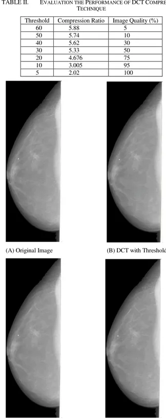
The same microclacification mammogram images are also processed using the DCT compression technique. The compression ratio and image quality is also considered in this evaluation as shown in Table II.
The experiment is tested using seven different threshold from 5 to 60. As shown in Table II, the most significant value for the threshold for DCT compression is 10 with image quality 95% as measured from the radiologist. Some of the processed mammogram image using DCT with different threshold value are shown in Fig. 6.
TABLE II. EVALUATION THE PERFORMANCE OF DCT COMPRESSION TECHNIQUE
Threshold Compression Ratio Image Quality (%)
60 5.88 5
50 5.74 10
40 5.62 30
30 5.33 50
20 4.676 75
10 3.005 95
5 2.02 100
(A) Original Image (B) DCT with Threshold 60
(C)DCT with Threshold 40 (D) Threshold with Threshold 10
A comparison is carried out between two compression techniques on mammogram images. As a result, the DCT compression technique shows good results in both image compression ratio and image quality comparing with SVD compression technique. For example, a mammogram image of size 5.17 MB will be compressed to 1.72MB using DCT technique and 3.496 MB using SVD Technique with good image quality at this ratio. The use of SVD in the process of compressing mammograms images does not benefit us as hoped in reaching the main goal which is compressing mammograms images as much as possible and keeping the quality needed by radiologist at the same time.
VI. CONCLUSION
The mammogram images are one of the large medical images that need to be processed and transmitted through the media. This paper presents an ongoing effort to reduce the image size in order to be easily processed and transmitted through the media. Two of lossy compression algorithms are presented in this paper which are singular value decomposition and discrete cosine transformation. Those compression algorithms are implemented on 40 microclacification images and an intensive comparisons are carried out to evaluate the performance of those techniques based on compression ratio and image quality. The SVD compression is applied to the mammogram images with different singular values that is from 5 to 230. The optimum value, that have a largest compression value with high quality result, was 155. The DCT compression is also applied of the same mammogram images using different threshold value that is from 5 to 60. The optimum threshold value, that have a largest compression value with high quality image, was at 10.
As a result, the DCT compression technique can effectively reduce the mammogram image size by 65% from the original size without affecting the suspicious regions such as microcalcifications. Whereas, the SVD compression technique can reduce the image by 33% from the original image size.
An interesting extension will be in using the Principal component analysis (PCA) to compress the mammogram images and compare it with the techniques listed in this paper. Another future work, CAD system will be implemented using the compressed database resulted from this paper. The true positive and false positive ratio in detection the microcalcification in mammogram images will highlighted for both compression techniques.
ACKNOWLEDGMENT
The authors are grateful to the Applied Science Private University, Amman, Jordan, for the full financial
REFERENCES
[1] V. J. Rehna & A. Dasgupt. “JPEG Image Compression using Singular Value Decomposition”. International Journal of Advances in Electronics Engineering, Vol. 1, No(1), 2001, pp.81-86.
[2] S. Kahu, & R. Rahate. “Image compression using singular value decomposition”. Int. J. Adv. Res. Technol, Vol. 2, No(8), 2013, pp.244-248.
[3] K. C. Sekaran, & K. Kuppusamy. “Performance Analysis of Compression Techniques Using SVD, BTC, DCT and GP”. IOSR Journal of Computer Engineering , Vol. 17, No.(1), 2015, pp.06-11.
[4] D. Gupta, P. Singh, & S. S. Nivedita.”A comparative study of image compression between Singular value decomposition, Block truncating coding, Discrete cosine transform and Wavelet”. International Journal of Computer Science and Network Security Vol. 12, No. (2), 2012, pp.100-108.
[5] K. Cabeen, & P. Gent. Image compression and the discrete cosine transform. College of the Redwoods.
[6] M. Dobrovolný, “The Quality Comparsion Of Svd And Dct Based Image Comperssion Methods For Embedded Devices”. J. of computer engineering, Vol. 5, No. (6), 2011, pp. 201-2012.
[7] A. Kaur, & J. Kaur. “comparison of DCT and DWT of Image Compression Techniques”. International Journal of Engineering Research and Development, 2012, pp. 49-52.
[8] K. Baker. “Singular value decomposition tutorial”. The Ohio State University, Vol. 24, 2005, .
[9] A. B. Watson. “Image compression using the discrete cosine transform”. Mathematica journal, Vol. 4, No.(1), 1994,, pp. 81-95.
[10] A. Aldroubi, M. Unser and M. Eden, “Cardinal spline filters: Stability and convergence to the ideal sinc interpolation,” IEEE Signal Process, Vol. 28, 1992, pp. 127-138.
[11] A.J. Patti, M.I. Sezan and A.M. Tekalp, “High-resolution image reconstruction from a low-resolution image sequence in the presence of time-varying blur,” Proc. IEEE Intl. Conf. Image Processing, Austin, TX, 1994, pp. 343-347.
[12] C.S. Chuah, and J.J. Leou, “An adaptive image interpolation algorithm for image/video processing,” Pattern Recognition, Elsevier, Vol. 34, 2001, pp. 2383-2393.
[13] H.S. Hou, and H.C. Andrews, “Cubic splines for image interpolation and digital altering,” IEEE Trans. Acoust. Speech Signal Process, ASSP, Vol. 26, 1978, pp. 508-517.
[14] K. Wakabayashi, “Evaluation of the effective information preservation method for binary image reduction,” System and Computers in Japan, Vol. 32, 2001, pp. 1-11.
[15] E. Aho, J. Vanne, K. Kuusilinna and T.D. Hämäläinen, “Comments on Winscale: An image-scaling algorithm using an area pixel model,” IEEE Trans. Circuits and Systems for Video Technology, Vol. 15, No.3, 2005, pp. 345-355.
[16] C.H. Kim, S.M. Seong, J.A. Lee and L.S. Kim, “Winscale: An image -scaling algorithm using an area pixel model,” IEEE Trans. Circuits and Systems for Video Technology, Vol. 13, No. 6, 2003, pp. 1-4.
[17] Hugo de las Herasa, Oleg Tischenkoa, Yuan Xub, Christoph Hoeschena, “Comparison of interpolation functions to improve a rebinning-free CT-reconstruction algorithm,” IEEE of Medical Physics, Vol. 4, 2007, pp. 430-445,.
[18] M. Masek, “Hierarchical segmentation of mammograms based on pixel intensity,” Ph.D. Thesis, The University of Western Australia, Australia, 2004
[19] M. Unser, A. Aldroubi and E. Eden, “Fast B-spline transforms for continuous image representation and interpolation,” IEEE Trans. Pattern Anal. Machine Intell., Vol. 13, 1991, pp. 277-285.
[20] M. Unser, A. Aldroubi and M. Eden, “Enlargement or reduction of digital images with minimum loss of information,” IEEE Trans. Image Processing, Vol. 4, 1995, pp. 247-258.
[21] R.G. Keys, “Cubic convolution interpolation for digital image processing,” IEEE Trans. Acoustics Speech and Signal Processing, Vol. 29, 1981, pp. 1153-1160.
[22] R.Y. Tsai, and T.S. Huang, “Multiframe Image Restoration and Registration,” Advance in Computer Vision and Image Processing, JAI Press, Greenwich, CT, Vol. 1, 1984, pp. 317-339.
[23] R.R. Schultz, and R.L. Stevenson, “A Bayesian approach to image expansion for improved definition,” IEEE Trans. Image Process., Vol. 3, 1994, pp. 233-242,.
[24] W.K. Pratt, “Digital Image Processing,” 3rd edition, Johm Willey & Sons Inc, 1991.
[26] Ravi kumar Mulemajalu , Shivaprakash Koliwad, “Lossless compression of digital mammography using base switching method”, J. Biomedical Science and Engineering, 2009, 2, 336-344
[27] Zhigang Liang, Xiangying Du, Jiabin Liu, Yanhui Yang, Dongdong Rong, Xinyu Yao & Kuncheng Li, “Effects Of Different Compression Techniques On Diagnostic Accuracies Of Breast Masses On Digitized Mammograms”, Acta Radiologica, Vol. 49, No.(7), 2009, 747-751. [28] A. AbuBaker. “Automatic Detection of Breast Cancer
Microcalcifications in Digitized X-ray Mammograms”. Ph.D., thesis, School of Informatics, University of Bradford-UK. (2008).
APPENDIX
Matlab Code for SVD inImage=imread(Image'); inImage=rgb2gray(inImage); inImageD=double(inImage);
% decomposing the image using singular value decomposition [U,S,V]=svd(inImageD);
dispEr = []; numSVals = []; for N=5:25:300 C = S;
% discard the diagonal values not required for compression C(N+1:end,:)=0;
C(:,N+1:end)=0;
% Construct an Image using the selected singular values D=U*C*V';
display and compute error figure;
buffer = sprintf('Image %d singular values', N) imshow(uint8(D));
title(buffer);
error = sqrt(sum(sum(S(N+1:end,N+1:end)))); imwrite(uint8(D),strcat(buffer,'.jpg') ); dispEr = [dispEr; error];
numSVals = [numSVals; N]; End
figure;
title('Error in compression'); plot(numSVals, dispEr); grid on
xlabel('Number of Singular Values used');
ylabel('Error between compress and original image');
__________________________________________________
Matlab Code for DCT
f1 = @(block_struct) dct2(block_struct.data); f2 = @(block_struct) idct2(block_struct.data); Im = imread('Image’);
Im1 = rgb2gray(Im);
%imwrite(Im1,'tigergray.jpg'); figure,imshow(Im);
J=blockproc(Im1,[8,8],f1); depth=find(abs(J)<40); J(depth) = zeros(size(depth)); K = blockproc(J,[8,8],f2)/255; figure,imshow(K);