Analysis-Design & Modification of A
Conventional Fan Assisted Heat Exchanger
(radiator) For Achieving Optimum
Thermal Characteristics.
1) Prof. Chavan Dattatraya K
Professor, Mechanical Engineering Department, MMCOE, Pune-52 Pune University, Maharashtra, India
PhD scholar JJT University, Rajasthan [email protected]
2) Prof. Dr. G S Tasgaonkar
Professor, Mechanical Engineering Department, ZES, DCOE, Narhe-Pune, Pune University, Maharashtra, India
Abstract :
The present heat exchangers/ radiators are rectangular in shape. But the air blown by the fan is circular in area, developing low velocity zones, high temperature regions in the corners. Therefore temperature and velocity readings are taken in all the four corners at various locations. It is claimed that stagnation zones are created in the corners and hence may be eliminated and proposed that the circular radiators, if developed, will be optimum for the improvement in efficiency. Experimentation has been carried out by considering temperature and velocity of air as variables, reveals that low velocity zones along with high temperature regions (low heat transfer zones) are developed as presumed in the corners. Extensive research work has been carried out on heat exchangers with square or rectangular shape. However no significant work has been done so far in case of new proposed radiators. The proposed design reduces weight & improves the efficiency of the radiator. As the weight is of main concern in almost all vehicles, refrigerators and air-conditioning systems, the proposed design proves to be a milestone in these realms. Due to reduction of weight, the cost of the equipment also reduces. Hence an optimized product with improved efficiency is developed. Considering number of vehicles, refrigerators, and air-conditioners used at National and International level, this optimized design gives great impact on any country’s economy in many ways.
Keywords— Heat exchanger, stagnation zones, low velocity areas, high temperature regions, optimization, etc. 1. AIMS AND OBJECTIVES
To optimize the fan assisted heat exchanger (radiator) by improvement in design. To provide a heat exchanger that will be more efficient and compact.
To provide a heat exchanger that will work with minimum power consumption for the fan and with maximum utilization of air flow.
To have a heat exchanger with minimum material and will thus be less costly
.
2. ORIGIN OF THE RESEARCH PROBLEM
The present heat exchangers/radiators are rectangular in shape. But the air blown by the fan is circular in area, developing low velocity zones at the corners. Therefore temperature readings will be taken in all the four corners at various locations and it will be claimed that stagnation zones are created in the corners and hence may be eliminated and proposed circular radiators will be optimum for the improvement in efficiency.
3. AUTOMOBILE RADIATOR
FIG.1
4. TYPES OF RADIATOR
FIG.2
5. RADIATOR &TUBES CONSTRUCTION & RADIATOR GEOMETRY.
FIG.3
Fig.4
Fig. shows a square-shaped heat exchanger with a fan provided to deliver air in a circular area.
If the length and breadth of the heat exchanger is equal to D, the effective area of such heat exchanger will be equal to D2.
6. SCHEMATIC TEST SET UP
FIG.5
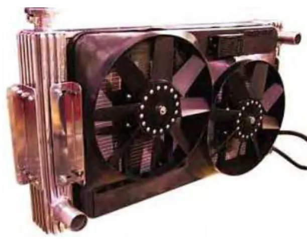
7. ACTUAL EXPERIMENTAL SET UP
FIG.6
8. BASIC RADIATOR DRAWING
9. TEMPERATUREREADINGSATCONSTANT RPM AND VARIABLE FLOW
FIG.8
10. 1ST
QUADRANT TEMPERATURE VS RADIAL DISTANCE
FIG.9
11. 2ND
QUADRANT TEMPERATURE VS RADIAL DISTANCE
12. 3RD
QUADRANT TEMPERATURE VS RADIAL DISTANCE
FIG.11
13. 4TH
QUADRANT TEMPERATURE VS RADIAL DISTANCE
FIG.12
14. VELOCITY READINGS: AT CONST. RPM & VARIABLE FLOW
15. 1ST
QUADRANT VELOCITY VS RADIAL DISTANCE
FIG.14
16. 2ND
QUADRANT VELOCITY VS RADIAL DISTANCE
FIG.15
17. 3RD
QUADRANT VELOCITY VS RADIAL DISTANCE
FIG.16
18. 4TH
QUADRANT VELOCITY VS RADIAL DISTANCE
19. TEMPRATUREREADINGSAT CONSTANT FLOW RATE ANDVARIABLERPM
FIG.18
20. 1ST
QUADRANT TEMPERATURE VS RADIAL DISTANCE
21. 2ND
QUADRANT TEMPERATURE VS RADIAL DISTANCE
FIG.20
22. 3RD
QUADRANT TEMPERATURE VS RADIAL DISTANCE
FIG.21
23. 4TH
QUADRANT TEMPERATURE VS RADIAL DISTANCE
24. VELOCITY READINGS AT CONST. FLOW RATE & VARIABLE RPM
FIG.23
25. 1ST
QUADRANT VELOCITY VS RADIAL DISTANCE
FIG.24
26. 2ND
QUADRANT VELOCITY VS RADIAL DISTANCE
27. 3RD
QUADRANT VELOCITY VS RADIAL DISTANCE
FIG.26
28. 4TH
QUADRANT VELOCITY VS RADIAL DISTANCE
FIG.27
29. TESTRESULTSANDCOMPARISONS:
At various flow rates 100, 120, 140, 160, 180 & 200 LPH & at 1500 RPM, various temperature and velocity readings are taken.
At constant flow rate of 100 LPH & at various speeds N=1600, 1700, 1800, 1900 & 2000 RPM, various temperature and velocity readings are taken.
It is observed that, low velocity zones (high temperature or low heat transfer regions) are observed in the corners & hence may be eliminated & proposed to have circular radiator for maximum efficiency.
30. CONCLUSION
The kinds of Conclusions Expected & Their possible values: For the new proposed heat exchanger,
•Low velocity zones, high temperature regions (low heat transfer regions) are identified in corners. •For optimum efficiency eliminate corners & develop radiator of Circular shape.
1. Design is compact. 2. Less material requirement. 3. Less power consumption for fan. 4. More efficient.
5. Since material saving is about 24%, cost saving on mass scale production will be about 20% once the dies are manufactured.
31. LIMITATIONS
•Bending of tubes in circular shape. •Inserting of fins in the tubes.
•Dies are to be manufactured for circular radiators which are exorbitantly costly.
32. REFERENCES
[1] ASME 2002 International Mechanical Engineering Congress & Exposition Heat Transfer Vol 6, Nov 17-22, 2002 USA Paper No. IMECE 2002-33888
[2] Optimization of Central heating radiator by Cihat Arslanturk & A. Feridum Ozguc. Applied Engg Vol 83, issue 11, Nov 2006, Pages 1190-1197.
[3] Shape optimization of vehicle radiator using CFD by, Maddiptla, Sridhar, Guessous, Laila, American Physical Society, Division of Fluid Dynamics, 55th Annual meeting KA006M dated 11/2002.
[4] Parametric studies on Automotive Radiators by, C. Oliet, A. Oliva, J.Castro & C.D. Perege- Segarre; Applied Thermal Engg Journal vol 27, issue 11-12;Aug 2007, Pages 2033-2043.
33. REFERENCEBOOKS
[6] Heat Exchanger Design (II Edition) [7] Arthur P Fraas.
[8] Published by John Wiley& Sons New York
[9] Heat Exchangers, Selection, rating,& Thermal design (II edition) [10] Sadik Kakak& Hongtan Lin