Optimum Evaluation of Thermal
Performance Characteristics of Micro Heat
Pipe using the Hadamard Matrix Design
Technique
aAchebo, J.I; bOmoregie, M.J. a,b
Department of Production Engineering University of Benin, Benin City, Edo State, Nigeria [email protected] ; [email protected]
Abstract
Micro heat pipes are on increasing demand as a result of current advances in technology consequently leading to a concomitant demand for continued research on how their thermal performance could be optimized; hence this study. The Hadamard matrix design approach was used to optimize the input parameters which generated an optimum combination of a 90o inclination angle, 8.70W heat input, and a 0.3 l/min coolant flow rate, these values match with the combination in sample trial 2. Further investigation revealed that sample trial 2 has a thermal resistance of 3.8oC/W with a threshold overall heat transfer coefficient of 750W/m2oC
Keywords: micro heat pipe, thermal resistance, hadamard matrix design, heat input, inclination angle, coolant flow rate
1. Introduction
Heat pipes have been found to be one of the best mediums for transporting large amounts of heat with a relatively little temperature difference along the given path or functional environment; and without the use of a pump or other moving parts. These pipes can be found in diameters as little as 3mm and much less, and have been determined to be a reliable and efficient means of dissipating heat in a myriad of applications such as laptop computers, micro-chips, and sundry integrated circuits. Effective heat dissipation and management goes a long way towards maintaining and increasing the service lives of these devices. Micro heat pipes are in increasing demand due to advances in current circuitry technology. Oinuma and Best [1] were of the opinion that Heat pipes are promising devices to remove thermal energy and keep functional environments such as integrated circuits at the proper working temperature. They said further that as the demand for high performance small electronic devices has increased, heat removal from these devices for space use is approaching critical limits. Khandekar et al [2] said that current trends and growing demands on the thermal management of modern microelectronics cannot accommodate the performance limitations posed by conventional heat pipes. Hossain et al [3] said that overheating of integrated circuit (IC), microchips and similar devices is a potential threat to these electronic components. It is therefore supremely important to facilitate optimum cooling of these electronic components, particularly regarding those found within the smaller electronic devices.
Continued research on how the thermal performance of these micro heat pipes could be improved is an ongoing venture. Fasula [4] wrote that traditional heat pipes are heat transfer devices that are capable of transporting large quantities of heat using small differences in temperature. For a more concise definition, Senthilkumar et al [5] defined a Heat Pipe as a heat transfer device used to transfer large amount of heat through a small cross sectional area with very small temperature difference. Hossain et al [3] also defined a heat pipe as a heat transfer mechanism that can transport large quantities of heat with a very small difference in temperature between the hot and cold interfaces. Heat pipes, they said are pencil-sized metal tubes that move heat from one end of the tube to the other without the aid of a pump.
Heat pipes could be classified as variable – conductance heat pipes because the magnitude and direction of the heat transfer can be controlled. Similarly, heat pipes can also be classified as micro-heat pipes because they are so small that the mechanisms controlling their operation are significantly different from those in more conventional/traditional heat pipes[6,7].
Nemec et al [8] said that a heat pipe has three sections: an evaporator section, an adiabatic (or transport) section and a condenser section [9]. Khare et al [10] explained the principle of heat pipe operation. They said that for a typical heat pipe, as heat is input at the evaporator, the working fluid is vaporised creating a pressure gradient in the pipe. This pressure gradient forces the vapor to flow along the pipe to a cooler section where it condenses giving up its latent heat of vaporisation. The working fluid is then returned to the evaporator by the capillary forces developed in the wick structure. From the above operating principle of the heat pipe, it can be deduced that the working fluid in the evaporator section is heated until equilibrium is reached and vapour
bubbles are formed continually. In this heating section, the temperature and pressure are very high. This increased pressure pushes the vapour bubbles forward toward the adiabatic or isothermal section, the flowability of the bubbles is aided by surface tension forces which are propagated by thermally induced buoyancy, colliding with one another until the bubbles burst and release vapours. As these vapours move toward the cooler section (condenser) of the tube, it loses its latent heat of vaporization and the temperature and pressure also reduces. At the condenser section the vapour condenses into films of liquid. These condensed liquid or fluid flows into the wick structure and saturates it. The tiny holes in the wick structure generate the capillary forces, including the pressure difference and the inter-connectivity of the tube ends which causes the shearing and moving of a mass fraction of the condensed fluid back to the evaporator section. Peterson [6] wrote that because heat pipes rely on vaporisation and condensation to transfer heat, selection of a suitable working fluid is an important factor in the design and manufacture of heat pipes. These fluids could either be ammonia, Freon 11 or 113, acetone, methanol, and water. He went further to say that a good working fluid should have a high latent heat of vaporisation, a high surface tension, a high liquid density, and a low liquid viscosity. Peterson [6] wrote that the wicking structure provides the pumping of the liquid from the condenser to the evaporator, it also ensures that the working fluid is evenly distributed over the evaporator surface. Peterson [6] suggested that in order to provide a flow path with flow resistance through which the liquid can be returned from the condenser to the evaporator, an open porous structure with a high permeability would be desirable. However, to increase the capillary pumping pressure, a small pore size is inevitable. The wick structure and working fluid generate the capillary forces required to pump liquid from the condenser to the evaporator and keep liquid evenly distributed in the wicking material. Heat pipe wicks can be classified as either homogeneous wicks or composite wicks.
It should always be borne in mind that particular attention should be directed at consequences temperature gradients created within these pipes. Khandekar et al [2] wrote that the net effect of all these temperature gradients within the system is to cause non equilibrium pressure condition which is known to be the primary driving force for thermo-fluidic transport. This high heat input also tends to produce more vapour bubbles and consequently more liquid is produced during condensation, which could just be enough to saturate the wick. Fasula [4] was of the opinion that a major criterion for thermal performance is the temperature drop along the heat pipe for a required heat load.
In this study, input parameters of the micro heat pipe as proposed by Hossain et al [3] was adopted, investigated, and optimized. Ornelas et al [11] emphasized that one way of achieving efficient heat pipe design is by determining optimal design parameters. Hossain et al [3] optimised input parameters but did not show how the optimization process was done in their paper. On the other hand, Senthilkumar et al [5] optimized the heat pipe input parameters using the Taguchi method. However, in this study, the Hadamard matrix design approach was adapted and applied to generate eight different combinations of the most important input parameters being the inclination angle, heat input, and the coolant flow rate. The idea being that by generating these various possible combinations and thereafter testing each one for its efficiency regarding actual heat transfer, the optimum combination could be singled out.
2. Materials and Methods
The micro heat pipe is fabricated in three sections being the evaporator section, adiabatic section, and the condenser section. Each heat pipe has an external diameter of 2.0 mm, with an internal diameter of 1.7 mm. The evaporator sections each measure 40 mm in length. For each heat pipe, NiCr-Cr thermocouples of 0.15 mm thickness were taped to the wall of the evaporator which was in turn connected to an AC power supply. The adiabatic sections measure 40 mm in length, and are made from reinforced glass. The pipes are therefore designed to exhibit the typical heat transportation and alternating behaviour of both the vaporized and condensed fluid. The condenser sections are 40 mm in length and are each connected to a water jacket with the flow rate controlled by a digital flow meter. The working fluid chosen and applied in each sealed heat pipe is acetone.
The method used in the optimization of the input parameters are summarized as follows: Definition of the object of the experiment.
O A high A low A high A low A
a A high A low A high A low A
H : , or 0
H : , or 0
a B high B low B high B low B
O C high C low C high C low C
a C high C low C high C low C
H : , or 0
H : , or 0
H : , or 0
Table 1 shows the Hadamard matrix design layout and the corresponding Overall heat transfer coefficient
Table 1: Hadamard Matrix Design and the corresponding Overall Heat Transfer Coefficient (U).
Response 0
1 2 3 4 5 6 7 U
1 710
2 750
3 780
4 900
5 840
6 720
7 860
8 810
A B C AB BC ABC AC
Trial
where
A = Inclination angle, Q = 30o – 90o B = Heat input, Q = 0.60W – 8.70W
C = Coolant flow rate, Mc = 0.3 l/min – 1.0 l/min
And the negative sign signifies a low level whereas the positive sign signifies a high level in the ranges above. For main variables, Table 2 shows the various input variable used to obtained their corresponding overall heat transfer coefficient.
Table 2: Input Parameters and Overall Heat Transfer Coefficient
90 0.60 0.30 710 90 0.87 0.30 750 90 0.87 1.00 780 30 0.87 1.00 900 90 0.60 1.00 840 30 0.87 0.30 720 30 0.60 1.00 860 30 0.60 0.30 810
A B C U
Table 3 shows the determination of the critical values of the main variables
Table 3: Determination of Critical Values of the Main Variables
710 710 710 750 750 750 780 780 780 900 900 900 840 840 840 720 720 720 860 860 860 810 810 810 210 70 390
4 4 4
52.5 17.5 97.5
A B C
Therefore, the critical values are
high A high B
high B high B
high C high C
52.5 17.5 97.5
X X
X X
X X
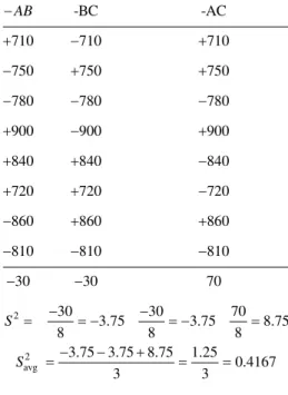
In computing the criterion for selection, the interactions are used to determine the standard deviation, S, as shown in Table 4,
Table 4: Determination of the Standard Deviation from the Interactions
2
-BC -AC
710 710 710
750 750 750
780 780 780
900 900 900
840 840 840
720 720 720
860 860 860
810 810 810
30 30 70
30 30 70
3.75 3.75 8.75
8 8 8
AB
S
2 avg
3.75 3.75 8.75 1.25
0.4167
3 3
0.6455
S
S
For φ = degree of freedom
At α = 0.05 (95% confidence level). Critical value of tα=0.05 = 1.895 [12]
Criterion for input parameters’ selection is
1 1
* 1 1
1.895 0.6455 0.8649 4 4
high low
X X
Criterion for decision
A low value is desirable. If the mean effect is positive, the low level is better; if the mean effect is negative, the high level is better [13].
If
XhighXlow
is negative and
XhighXlow
>
*
high low
X X , accept Ha that high is better than low.
If
XhighXlow
is positive and greater than
*
high low
X X , accept Ha that low is better than high.
Using the input parameters’ selection criterion factor,
*
high A low A 52.5 high low 0.8649
X X X X
We accept Ha that high is better than low.
*
high B low B 17.5 high low 0.8649
X X X X
We accept Ha that high is better than low.
*
high C low C 97.5 high low 0.8649
X X X X
We accept Ha that low is better than high.
The optimum formulation here would be Inclination angle should be 90o
Heat input should be 8.70W
Coolant flow rate should be 0.3l/min.
This optimum formulation was used to determine the thermal resistance of the micro pipe and a thermal resistance of 3.8oC/W was obtained.
3. Discussion of Results
The research study was carried out to determine the optimum combination of input parameters that would give the most efficient value of an overall heat transfer coefficient and thermal resistance of a micro-heat pipe. The input parameters and their attendant ranges chosen are the inclination angle in the range of 30o to 90o; the heat input in the range of 0.60W to 8.70W; and the coolant flow rate in the range of 0.3 l/min to 1.0 l/min. The Hadamard matrix design technique was used to determine optimum values of these input parameters. Following the necessary tests, the optimum values gleamed from the adaptation of the model are an inclination angle of 90o, heat input of 8.70W, and a coolant flow rate of 0.3 l/min. These values indicate that for the maximum heat input value of 8.70W, a high heat transfer coefficient would be generated, this would normally have a high wall temperature at the evaporator section, low temperature at the vapor-liquid interface and lower wall temperature at the condenser section, creating an ideal temperature gradient within the heat pipe (tube). The heat pipe experimental procedures conducted at vertical positions, that is, at an angle of 90o has produced the best results in terms of thermal performance. With the reduction in the flow rate of the coolant at 0.3 l/min, it would be possible to maintain an acceptable operating temperature at the condenser section so that a small temperature gradient can be maintained.
However, from the test conducted as shown in Fig. 1, it is seen that at the evaporator section, the wall temperature of the heat pipe (tube) is 54oC, as the vapour bubbles move towards the adiabatic section (vapor-liquid interface) the temperature drops steeply and stabilizes in the adiabatic section toward the condenser section, almost maintaining a controlled temperature and eventually drops spheriodally in the condenser section. This spheriodal cooling was as a result of the low flow rate of the applied coolant. Fig. 2 explains the summary of the results obtained in the experiment.
Fig 1: Surface Temperature vs Tube Length Fig. 2: Thermal Resistance vs Overall Heat Transfer Coefficient
From Fig. 2, it is shown that from the eight experimental trials obtained by using the Hadamard matrix design, sample trial 2 fits optimum formulation obtained. When compared to other sample trials, sample trial 2 has a threshold overall heat transfer coefficient of 750W/m2 oC, producing the lowest thermal resistance of 3.8oC/W. Ornelas et al [11] wrote that in the search for a more efficient heat pipe design, thermal resistance is often used as one of the key measures of overall performance. They said that thermal resistance defines the impedance to the transfer of heat when not heated uniformly. They concluded by saying that in order to improve the heat pipe’s performance, its thermal resistance must be lowered as much as possible. This has been achieved in this study.
4. Conclusion
Micro heat pipe input parameters as proposed by Hossain et al [3] and used in this study were optimized using the Hadamard matrix design. Sample trial 2 was found to match the optimal combination of input parameters obtained. The thermal resistance of the other seven sample trials including the optimum sample trial 2, were determined and it was found that sample trial 2 has the lowest thermal resistance which also confirms its claim of having the optimum input parameters. A threshold value for the overall heat transfer coefficient was also determined. This study has been able to optimize the input parameters of a micro heat pipe, generating encouraging results. It also reveals a step by step approach of the adaptation and the application of the Hadamard matrix design.
References
[1] Oinuma, R. and Best, F.R. Fundamental Study of Heat Pipe Design for High Heat Flux Source. http://tfaws.nasa.gov/TFAWS02/Data/Thermal/Oinuma.pdf (accessed December 18, 2012)
[2] Khandekar, S.; Schneider, M. and Groll, M. Mathematical Modelling of Pulsating Heat Pipes: State of the Art and Future Challenges. Proc. of 5th ISHMT – ASME – Joint International Conference on Heat and Mass Transfer, Kolkata, India, Tata McGraw Hill, 856 – 862, (2002).
[3] Hossain,R.A.; Chowdhuri, M.A.K. and Feroz, C.M. Design, Fabrication and Experimental Study of Heat Transfer Characteristics of a Micro Heat Pipe. Jordan Journal of Mechanical and Industrial Engineering, 4.(5), 531 – 542, ( 2010).
[4] Fasula, C. Oscillating Heat Pipes (OHP), Masters of Science in Mechanical Engineering and Applied Mechanics, University of Rhode Island, (2009).
[5] Senthilkumar R.; Vaidyanathan S. and Sivaraman B., Thermal Analysis of Heat Pipe using Taguchi Method. International Journal of Engineering Science and Technology. 2 (4), 564 – 569. (2010)
[6] Peterson, G.P., Chapter 12 - Heat Pipes. McGraw - Hill Handbook of Heat Transfer, 3rd Edition, W.M. Rohnsenow, J.P.Hartnett and Y.I.Cho (eds), McGraw Hill Publishing Co., Washington D.C. 12.1 - 12.20 (1998)
[7] Brennan, P.J. and Kroliczek, E.J., Heat Pipe Design Handbook. Volume 1. B & K Engineering, Inc. Towson, Maryland. Contract No. NASA 23406 (1979)
[8] Nemec, P.; Caja, A. and Malcho, M. Thermal Performance Measurement of Heat Pipes. Global Journal of Technology and Optimization. 2,. 1. (2011)
[9] Ochterbeck, Jay M. Heat Pipes, in Heat Transfer Handbook 1, Edition – July (2003).
[10] Khare, A.; Amitesh, P. and Tiwari, A.C.. Design Development of Test – Rig to Evaluate Heat Pipes in Comparison to Conventional Water Jackets in Mould Cooling. VSRD International Journal of Mechanical Automobile and Production Engineering, 2 (1), 34 – 43. (2012)