Advances in Mechanical Engineering 2015, Vol. 7(11) 1–11
ÓThe Author(s) 2015 DOI: 10.1177/1687814015618155 aime.sagepub.com
Impact of ribs on flow parameters and
laminar heat transfer of water–
aluminum oxide nanofluid with
different nanoparticle volume fractions
in a three-dimensional rectangular
microchannel
Omid Ali Akbari
1, Davood Toghraie
1and Arash Karimipour
2Abstract
This article aims to study the impact of ribs on flow parameters and laminar heat transfer of water–aluminum oxide nanofluid with different nanoparticle volume fractions in a three-dimensional rectangular microchannel. To this aim, com-pulsory convection heat transfer of water–aluminum oxide nanofluid in a rib-roughened microchannel has been numeri-cally studied. The results of this simulation for rib-roughened three-dimensional microchannel have been evaluated in contrast to the smooth (unribbed) three-dimensional microchannel with identical geometrical and heat–fluid boundary conditions. Numerical simulation is performed for different nanoparticle volume fractions for Reynolds numbers of 10 and 100. Cold fluid entering the microchannel is heated in order to apply constant flux to external surface of the micro-channel walls and then leaves it. Given the results, the fluid has a higher heat transfer with a hot wall in surfaces with ribs rather than in smooth ones. As Reynolds number, number of ribs, and nanoparticle volume fractions increase, more temperature increase happens in fluid in exit intersection of the microchannel. By investigating Nusselt number and fric-tion factor, it is observed that increase in nanoparticle volume fracfric-tions causes nanofluid heat transfer properties to have a higher heat transfer and friction factor compared to the base fluid used in cooling due to an increase in viscosity.
Keywords
Numerical simulation, three-dimensional microchannel, nanofluid, friction factor, heat transfer
Date received: 28 April 2015; accepted: 17 September 2015
Academic Editor: Oronzio Manca
Introduction
One of the most fundamental issues in electronics industry is thermal management of electronic devices, particularly with regard to maximum working tempera-ture limitations, and uniform heat distribution in the devices. These factors directly influence performance, cost, and reliability of electronic devices.1An investiga-tion of recent articles shows an increasing demand for reducing weight and volume of electronic devices and
1Department of Mechanical Engineering, Islamic Azad University,
Khomeinishahr Branch, Khomeinishahr, Iran
2Department of Mechanical Engineering, Islamic Azad University,
Najafabad Branch, Isfahan, Iran
Corresponding author:
Davood Toghraie, Department of Mechanical Engineering, Islamic Azad University, Khomeinishahr Branch, Khomeinishahr 84175-119, Iran. Email: [email protected]
increasing their power. Nowadays, the main constraint in producing electronic devices is lack of an efficient technique to decrease heat in these devices. In the last two decades, manufacturing micro devices with micron structures and compressing electronic devices have developed. Future microelectronic components have been designed for consumptions higher than
1000 (W/m2). These high heat fluxes cannot be easily
transferred using current cooling methods. In recent years, efforts have been made to produce cooling
devices such as compressed electronic components.1
Recently, several possible cooling solutions including two-phase flow, nucleate boiling, microchannel heat sinks, using nanofluids, and collision of gases with high speed have been investigated by different authors. Among the cooling methods, microchannel heat sink
has proved to be a high-performance cooling method.2
Significant development of micro-manufacturing meth-ods in the past decade has made microchannel reactors able to have different practical applications in several fields. Due to business benefits and practical applica-tions of the current discussion, many studies have been carried out by researchers in this field.
Gunnasegaran et al.3investigated the effect of geo-metric parameters and heat transfer of water fluid flow in a microchannel. Their results showed that the best uniform distribution of temperature and heat transfer coefficient can be obtained in channels with the smal-lest hydraulic diameters.
Chen and Ding4 investigated the heat transfer
per-formance of microchannels with water–aluminum oxide nanofluid in different nanoparticle volume frac-tions concluding that thermal resistance and tempera-ture distribution in microchannels significantly vary in response to the effect of inertia force.
Mohammed et al.5also investigated numerical heat
transfer in a rectangular heat exchanger microchannel. Their results showed that when there is a slight increase in pressure drop, nanofluids increase heat properties and performance of heat exchangers. In addition, these
authors6 numerically evaluated the effects of using
nanofluids on heat transfer and nanofluid flow para-meters in a rectangular heat sink for Reynolds numbers of 100–1000 using water–aluminum oxide nanofluid with volume percentage of 1%–5%. They found that as volume percentage of nanoparticles increases, heat transfer coefficient and shear stress increase, and that using nanofluids leads to a slight pressure drop along the microchannel.
Manca et al.7performed a numerical analysis on air
displacement flow in square, rectangular, triangular, and trapezoid channels and concluded that in turbulent fluid flow regime, friction factor increases as Nusselt number increases.
Through their experimental research on friction effects in turbulent flow and heat transfer behaviors of
the nanofluid composed of TiO2and Al2O3particles in
a round tube, Pak and Cho8 concluded that Nusselt
number increases by increasing nanoparticle concentra-tion. Maiga et al.9investigated benefits of using nano-fluid and showed that using nanoparticles causes intense effects of shear stress on the wall.
Izadi et al.10 investigated compulsory displacement
flow in extended laminar mode in between two con-centric circles and concluded that volume fraction of nanoparticles has an important effect on thermal pro-files but no effect on dimensionless velocity. Till date, many studies have been conducted to evaluate the fluid flow in macro and microchannels with surface
rough-ness.11–13 Among these investigations, methods to
enhance the heat transfer are suggested and studied. This study was also carried out to study heat trans-fer and computational fluid dynamics of nanofluid in microchannel, for Reynolds numbers 10 and 100, and
volume fraction ofu= 0%24% solid nanoparticles of
Al2O3. The main difference between this study and
other studies is as follows:
1. The use of non-circular surfaces to increase the
surface heat transfer;
2. The use of nanofluids for working fluid;
3. The use of a tooth for better mixing of fluid
flow.
Statement of the problem
The analysis was performed on a three-dimensional rectangular microchannel investigated in two individual modes of (a) and (b). In mode (a), two rectangular ribs have been made in the middle of the length of the microchannel in opposite upper and lower walls. Mode (b) is the same as mode (a) with the difference that there is only one rectangular rib in this mode whose height is half of the ribs’ heights in mode (a). To create the mode of developed hydrodynamic flow, the micro-channel in entrance and exit areas has the entrance length with the dimensions shown in the figure. This length is insulated in the entrance and exit of the micro-channel from four sides. Considering Figure 1, a uni-form heat flux equal to q$= 25,000 (W/m2) is applied to the central area of the microchannel from four sides.
Figure 1 shows the microchannel investigated in this study in terms of heat boundary conditions and entrance and exit length areas in two and three
dimen-sions. The microchannel length is l= 2.5 mm and its
height ish= 25mm.
In Figure 2, the lengths arel1=l3= 750mm and the
microchannel width is w= 25mm. The length is
l2= 1000mm. The investigated modes (a) and (b) are
modes (a) and (b) and the smooth channel is the posi-tion of ribs inl2area in upper and lower walls of the
microchannel as in Figure 3.
The temperature of the inlet fluid to the
microchan-nel is Tc= 293 K. The flow in laminar mode is
investigated for Reynolds numbers 10 and 100. Agent fluid is water and aluminum oxide powder (Al2O3) with
a volume fraction of (u= 020.04).
In this study, three-dimensional flow is assumed to be incompressible, Newtonian, laminar, and single-phased. In the entrance areas of the microchannel, fluid is entered with uniform velocity, and the shape of nano-particles is assumed to be uniform and spherical.
Governing equations for laminar
nanofluids
Governing dimensionless equations include equations of continuity, momentum, and energy, which are solved for permanent and laminar mode in Cartesian coordinates14
∂U
∂X +
∂V
∂Y +
∂W
∂Z =
0 ð1Þ
U∂U
∂X +V
∂U
∂Y +W
∂U
∂Z =
∂P
∂X +
1
rnfnf
1
Re
∂
∂X mnf ∂U
∂X
+ ∂
∂Y mnf ∂U
∂Y
+ ∂
∂Z mnf ∂U
∂Z
ð2Þ
U∂V
∂X +V
∂V
∂Y +W
∂V
∂Z =
∂P
∂Y +
1
rnfnf
1
Re
∂
∂X mnf ∂V
∂X
+ ∂
∂Y mnf ∂V
∂Y
+ ∂
∂Z mnf ∂V
∂Z
ð3Þ
Figure 1. Three-dimensional and two-dimensional schematic of the investigated smooth microchannel.
Figure 2. The modes (a) and (b) as investigated in this study.
Figure 3. Investigating the position of ribs inl2area for the
U∂W
∂X +V
∂W
∂Y +W
∂W
∂Z =
∂P
∂Z +
1
rnfnf
1
Re
∂
∂X mnf ∂W
∂X
+ ∂
∂Y mnf ∂W
∂Y
+ ∂
∂Z mnf ∂W
∂Z
ð4Þ
U ∂u
∂X +V
∂u
∂Y +W
∂u
∂Z =
1
af Cpr
nf
1
Re Pr
∂
∂X Knf ∂u
∂X
+ ∂
∂Y Knf ∂u
∂Y
+ ∂
∂Z Knf ∂u
∂Z
ð5Þ
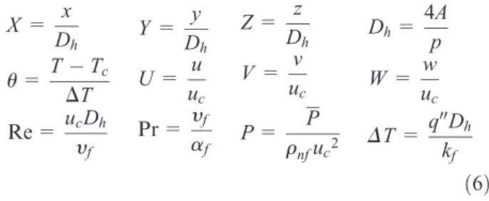
In the above equations, the following dimensionless parameters are used14
X= x Dh
u=TTc
DT
Re =ucDh
yf
Y= y Dh
U= u uc
Pr = yf
af
Z= z Dh
V= v uc
P= P
rnfuc2
Dh=
4A
p
W= w uc
DT=q
00D
h kf
ð6Þ
In the above equation,X, Y, Zare the coordinates of the axes along thex, y, z, respectively. Also, parameters of U, V, W are the dimensionless velocities along the axes, x, y, z, respectively. Dh, u, P, Pr, Re, DT
para-meters are the hydraulic diameter, temperature and pressure dimensionless, Prandtl number, Reynolds number, and the temperature difference, respectively.
Nanofluid properties
Thermophysical properties of the nanofluid and alumi-num powder nanoparticles are presented in Table 1. The following relationship is used for calculating nano-fluid density15,16,17
rnf=ð1uÞr
f+urp ð7Þ
In equation (7), parameters rnf,rf,u,rs refer to nanofluids and base fluid density, the volume fraction of solid nanoparticles and solid nanoparticle density, respectively.
Effective heat distribution coefficient of the nano-fluid is calculated from the following formula18
anf = keff
rCp
nf
ð8Þ
In the above equation, parameters anf,Cpnf,keff are thermal diffusivity, specific heat capacity, and effective thermal conductivity of nanofluids, respectively.
Specific heat capacity of the nanofluid is calculated by the following formula19
rCp
nf =ð1uÞ rCp
f+u rCp
p ð9Þ
Brinkman relationship20,21 is used to calculate effec-tive dynamic viscosity of nanofluid
mnf = mf
1u
ð Þ2:5 ð10Þ
In equation (10), expressions mnf,mf are dynamic
viscosity of fluid and nanofluids, respectively. To calcu-late effective thermal conductive coefficient of nano-fluid for suspensions having sphere-like particles, the relationship provided by Patel et al.22is used
keff=kf 1+ kpAp kfAf
+ckpPe Ap kfAf
ð11Þ
where experimental constant is c= 36,000, and terms
kf,kp, Pe refer to the thermal conductivity of the base fluid and solid nanoparticles and Peclet number, respectively
Ap Af
=df dp
u
1u ð12Þ
Pe =usdp
af
ð13Þ
where water molecule diameter equals df= 2 A˚´,
alumi-num nanoparticle molecule diameter equalsds= 50 nm,
andusvalue is Brownian motion velocity of
nanoparti-cles and is calculated by the following formula
us=
2kbT
pmfd2 p
ð14Þ
where kb= 1.3807310223
J/K value is Boltzmann constant.23
Table 1. Thermophysical properties of the nanofluid and solid nanoparticle.17
Water Al2O3 Nanofluid
u= 0.01 u= 0.02 u= 0.03 u= 0.04
Cp(J/kg K) 4179 765 4047 3922.4 3804.7 3693.2
r(kg/m3) 997.1 3970 1026.8 1056.6 1086.3 1116
k(W/m K) 0.613 40 0.6408 0.6691 0.698 0.7276
m(Pa s) 8.9131024 – 9.13
31024 9.37
31024 9.61
31024 9.86
To calculate the local Nusselt number along the microchannel walls, the following equation is used,
where the values ofTwandTmare average temperature
of the wall and bulk temperature of the fluid,24 respec-tively, andq00is the heat flux applied to the surfaces of microchannels
Nuave=
q00Dh kfðTwTmÞ
ð15Þ
The following equation is used for calculate fanning friction factor25
f =2DPDh
L
1
ru2 in
ð16Þ
In equation (16),DP, L,uin refer to pressure drop, the length of channel and inlet velocity of the fluid in the microchannels, respectively. The degree of pumping power is calculated from the following equation26–30
Pp =A uinDP ð17Þ
In equation (17),Ais the inlet cross-sectional area of microchannel. For general evaluation of heat–fluid per-formance of the rib-roughened microchannel, perfor-mance evaluation criterion (PEC) parameter is defined as heat efficiency as follows31
PEC = Nuave Nuave,s
f fs
ð1=3Þ ð18Þ
In the definition of factor PEC, expressions
Nuave, Nuave,s refer to average Nusselt number in
smooth and the toothed microchannel, respectively, and terms f, fs are the average friction coefficient in
smooth and toothed microchannel, respectively.
Poiseuille number is calculated from the following equation32,33
Cf=f Re ð19Þ
Numerical method
Equations governing laminar flow of the water– aluminum oxide nanofluid in three-dimensional and steady state mode are continuity, momentum, and energy equations. These equations are solved and
dis-cretized by finite-volume method. Semi-Implicit
Method for Pressure Linked Equations—Consistent (SIMPLEC) algorithm is used to solve velocity–
pressure coupled equations. The remainder of 1026
is selected as the acceptable remainder to obtain exact answers and ignorable error from the current problem solving and using less computer memory in numerical simulation process maximum.
Numerical procedure validation
In the numerical solution of the current problem, the results from the numerical simulation were validated through the results of the reference34with identical geo-metric and boundary conditions to ensure the accuracy of the results. With regard to Figure 4, the average Nusselt number in this study is in good agreement with
the study performed in the reference.34 The average
Nusselt number in smooth channel increases by increas-ing Reynolds number, which is due to better confound-ing of fluid layers as a result of an increase in velocity in higher Reynolds number, which in turn causes a decrease in heat gradient in-between the layers far from the hot surface of the microchannel. As nanoparticle volume fraction increases, the average Nusselt number increases as well due to the existence of solid nanoparti-cles in between fluid layers. Existence of nanopartinanoparti-cles improves heat conductivity properties of the fluid and reinforces heat transfer mechanisms in micron scale.
Grid independence
In the research ahead, to achieve optimal grid number, the effect number of grid will be investigated on the heat transfer and fluid flow parameters. The grid inde-pendence study of the present numerical simulation is shown in Table 2, which illustrates the results for Reynolds numbers of 100 and volume fractions of 4% in case (b) through average value of Nusselt number, friction factor variation, and convection heat transfer coefficient. The results indicate that for the grid num-ber of 220,000, the average Nusselt numnum-ber and friction
factor variation and convection heat transfer coefficient have a maximum error of less than 5%. Furthermore, for this number of grids, compared to 295,000 grids, the computation time is reduced and the numerical error is negligible.
Results and discussions
In this numerical study, laminar flow of the water– aluminum oxide nanofluid was investigated in a rectan-gular three-dimensional microchannel. This research studied the effect of ribs on dynamic behavior of the computational fluids of nanofluid in different modes of (a) and (b). The results embrace the average Nusselt number, average convection heat transfer coefficient, heat–fluid PEC, pumping power, friction factor, and Poiseuille number. These results were considered for two modes (a) and (b) and are presented as a function of nanoparticle volume fraction. Calculated values for each parameter in each mode of (a) and (b) are compared with similar parameters in the smooth micro-channel with identical geometric and boundary (heat– fluid) conditions with pure water cooling fluid. The
results of this study are calculated for Reynolds numbers of 10 and 100 and volume fractions of
u= 0%–4% aluminum nanoparticle. Figure 5 shows
the friction factor diagram in the smooth microchannel. It is observed that friction factor in the smooth channel decreases by increasing Reynolds number. With regard to the figure, friction factor of the flow with Reynolds number of 10 is about 10 times as large as that with Reynolds number of 100 due to more fluid contact with microchannel surfaces in lower velocities. By increasing nanoparticle volume fraction, friction factor increases due to an increase in shear stress in walls as a result of the existence of solid particles in cooling fluid. The main reason should be that the dynamic viscosity increased very quickly as the nanoparticle volume frac-tion increased, so the flowability of nanofluid turned worse, which led to an increase in the thickness of boundary layer. As a result, the friction factor increased.
Figure 6 compares friction factor in each mode of (a) and (b) to the smooth microchannel. It is observed that due to the existence of the ribs, friction factor has been significantly increased. Friction factor in mode (a) is larger due to the pressure drop resulting from an
Table 2. Grid study for Re = 100,u= 0.04 in case (b).
Grids Num f have
130,000 9.985 0.56 227,823.1
175,000 10.760 0.6303 256,896.045
220,000 11.381 0.6604 279,064.7
295,000 11.401 0.677 292,034.23
Figure 5. Friction factor diagram in the smooth microchannel
increase in the number of ribs with higher heights com-pared to mode (b). In both modes, increasing nanopar-ticle volume fraction increases friction factor as well. In comparison to Reynolds numbers 10 and 100, in the case of (a), the coefficient of friction is increased, which causes a further drop in velocity in this case, and graphs in case (b) to have a higher level.
Figure 7 shows the value of average Nusselt numbers in each mode of (a) and (b) compared to the smooth microchannel. The average Nusselt number increases as Reynolds number and nanoparticle volume fraction increase. The average Nusselt number ratio in micro-channel (a) has increased compared to mode (b) in each Reynolds number of 10 and 100, which is due to lower heat gradient in rib-roughened surfaces resulting from the existence of more ribs with higher heights. By put-ting a rib in the direction of fluid flow, a better mixing of the fluid layers happens, and better heat distribution between layers of the fluid is performed. With regard to Figure 7, the increase in heat transfer in comparison to smooth microchannels in both Reynolds numbers 10 and 100 is considerable.
Figure 8 shows the average convection heat transfer coefficient in each mode of (a) and (b) compared to the smooth microchannel with identical conditions. Like the average Nusselt number, the value of this coefficient increases by an increase in Reynolds number and nano-particle volume fraction in both modes. The increasing trend of this coefficient is larger in higher Reynolds and with higher nanoparticle volume fractions. Increase in heat transfer coefficient at Reynolds number 100, com-pared to Reynolds number 10, is considerably more. In
case (a), when Reynolds number is 100 and the 4% vol-ume fraction of nanoparticles, it is possible to achieve a heat transfer equivalent to 4.5 times as large as that in smooth microchannel.
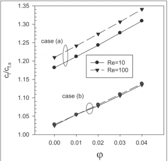
Figure 9 shows the Poiseuille number ratio for the modes of (a) and (b) compared to the smooth channel. Due to the existence of ribs, Poiseuille number has increased in the rib-roughened microchannel. Ribs cause more contact surface of fluid and walls and
Figure 7. The average Nusselt number ratio diagram in different nanoparticle volume fractions.
Figure 8. The average convection heat transfer coefficient ratio diagram in different nanoparticle volume fractions.
create an obstruction in the microchannel, which has a large effect on pressure drop and causes an increase in Poiseuille number compared to the smooth channel. Increasing volume fraction of solid nanoparticles increases fluid viscosity, which in turn increases friction factor and Poiseuille number.
In Figure 10, pumping power ratio for each modes of (a) and (b) is compared to the smooth microchannel. It is observed that due to the existence of nanoparticles, the value of density and dynamic viscosity of the cool-ing fluid increases; and on the other hand, the existence of the ribs in the microchannel causes an obstruction, which increases the pumping power given the above-mentioned points. Increased flow rate in microchannels caused by an increase in the fluid inlet velocity requires a higher pumping power. For both cases (a) and (b), the pumping power diagram at Reynolds number 100, in comparison to the Reynolds number 10, is at a higher level.
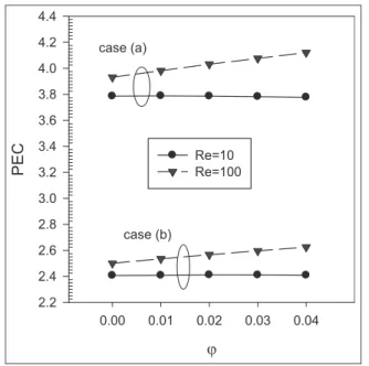
In Figure 11, PEC of rib-roughened microchannels (a) and (b) evaluates the relation of heat transfer value to friction effects and compares both channels in rela-tion to the smooth channel in identical condirela-tions. By comparing the diagrams, it can be found that an increase in the number of ribs with higher heights causes higher efficiency of microchannel (a). This cri-terion increases by an increase in volume fraction for both modes of (a) and (b) which is due to higher effects of heat transfer compared to nanoparticle friction effects. In Reynolds number 10 for both cases, (a) and (b), diagram PEC, with an increase in volume fraction, the trend is the decreasing, which expresses a significant
increase in the coefficient of friction against an increase in heat transfer. In Reynolds number 100, the behavior of diagram PEC is contrary to Reynolds number 10, and increase in heat transfer is significant. The diagram with increasing volume fraction is uptrend.
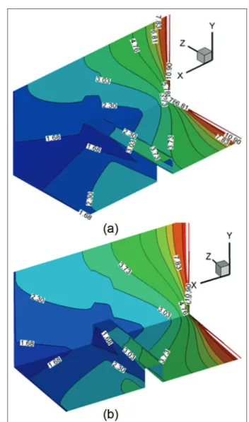
Figures 12 and 13 evaluate local Nusselt number contours in the walls of microchannels (a) and (b) in
volume fractions ofu= 0%–4% for Reynolds number
100. Figure 12(a) relates to mode (a) in Reynolds num-ber 100 and pure water fluid. Figure 12(b) relates to mode (a) in Reynolds number 100 and volume frac-tions of 4% of the solid nanoparticle.
Figure 13(a) relates to mode (b) in Reynolds number 100 and pure water fluid. Figure 13(b) relates to mode (b) in Reynolds number 100 and volume fraction of 4% of the solid nanoparticle. It is observed that in mode (a), due to the existence of more ribs, in each nanoparti-cle volume fraction, the areas with higher local Nusselt number and those with lower heat distribution gradient increase compared to the mode (b). In addition to the number of ribs and higher height of ribs, increase in nanoparticle volume fraction in each Figures 12(b) and 13(b) compared to Figures 12(a) and 13(a) causes better distribution of heat transfer in the microchannel.
Conclusion
In this study, heat transfer of laminar flow of water–aluminum oxide nanofluid was investigated in rib-roughened three-dimensional microchannel, and the results were compared with those from the smooth microchannel in identical geometric and boundary
Figure 10. Pumping power ratio diagram in different nanoparticle volume fractions.
conditions. According to the results obtained in this study, it can be found that using ribs in microchannels causes an increase in heat transfer rate and a decrease in heat gradient in between layers of cooling fluid.
Existence of nanoparticles in the cooling fluid also has a significant effect on increasing heat transfer, which is reinforced with an increase in Reynolds num-ber. However, on the other hand, existence of ribs in microchannel causes a pressure drop due to the obstruction compared to the smooth channel, which in turn causes an increase in friction factor and pumping power. Although using nanofluid causes an increase in heat transfer, existence of nanoparticles in the cooling fluid causes an increase in density and viscosity, which in turn increases shear rate in walls and friction factor and pumping power. Finally, efficiency of using ribs and nanofluid in the microchannel should be evaluated by PEC. Given the diagrams of Nusselt number ratio, a heat transfer of up to 4.5 times of the smooth channel can be obtained using nanofluid and ribs in the microchannel.
Declaration of conflicting interests
The author(s) declared no potential conflicts of interest with respect to the research, authorship, and/or publication of this article.
Funding
The author(s) received no financial support for the research, authorship, and/or publication of this article.
References
1. Hung T and Yan W. Enhancement of thermal perfor-mance in double-layered microchannel heat sink with
nanofluids.Int J Heat Mass Tran2012; 55: 3225–3238.
2. Farsad E, Abbasi SP, Zabihi MS, et al. Numerical simu-lation of heat transfer in a microchannel heat sinks using
nanofluids.Heat Mass Transfer2011; 47: 479–490.
3. Gunnasegaran P, Mohammad HA, Shuaib NH, et al. The effect of geometrical parameters on heat transfer
Figure 12. Local Nusselt number contours for the mode in Reynolds number 100 with volume fraction of (a)ua= 0 and (b) ub= 0.04.
characteristics of microchannel heat sink with different
shapes.Int Commun Heat Mass2010; 37: 1078–1086.
4. Chen CH and Ding CY. Study on the thermal behavior and cooling performance of a nanofluid-cooled
micro-channel heat sink.Int J Therm Sci2010; 50: 378–384.
5. Mohammed HA, Gunnasegaran P and Shuaib NH. Influence of nanofluids on parallel flow square
micro-channel heat exchanger performance.Int Commun Heat
Mass2011; 38: 194–201.
6. Mohammed HA, Gunnasegaran P and Shuaib NH. Heat transfer in rectangular microchannels heat sink using
nanofluids.Int Commun Heat Mass2010; 37: 1496–1503.
7. Manca O, Nardini S and Ricci D. Numerical investiga-tion of air forced convecinvestiga-tion in channels with differently
shaped transverse ribs.Int J Numer Method H2010; 21:
618–639.
8. Pak BC and Cho YI. Hydrodynamic and heat transfer study of dispersed fluids with submicron metallic oxide
particles.Exp Heat Transfer1998; 11: 151–170.
9. Maiga SEB, Nguyen CT, Galanis N, et al. Heat transfer behaviours of nano-fluids in a uniformly heated tube.
Superlattice Microst2004; 35: 543–557.
10. Izadi M, Behzadmehr A and Jalali-Vahida D. Numerical study of developing laminar forced convection of a
nano-fluid in an annulus.Int J Therm Sci2009; 48: 2119–2129.
11. Zhang CB, Chen YP, Deng Z, et al. Role of rough surface
topography on gas slip flow in microchannels.Phys Rev
E86: 016319.
12. Chen YP, Zhang CB, Fu PP, et al. Characterization of surface roughness effects on laminar flow in
microchan-nels by using fractal cantor structures. J Heat Transf
2012; 134: 051011.
13. Chen YP and Cheng P. Heat transfer and pressure drop
in fractal tree-like microchannel nets. Int J Heat Mass
Tran2002; 45: 2643–2648.
14. Sheikhzadeh GA, Ebrahim Qomi M, Hajialigol N, et al.
Effect of Al2O3-water nanofluid on heat transfer and
pressure drop in a three-dimensional microchannel.Int J
Nano Dimens2013; 3: 281–288.
15. Aminossadati SM and Ghasemi B. Natural convection cooling of a localized heat source at the bottom of a
nanofluid-filled enclosure.Eur J Mech B Fluid2009; 28:
630–640.
16. Malvandi A and Ganji DD. Magnetohydrodynamic
mixed convective flow of Al2O3–water nanofluid inside a
vertical microtube. J Magn Magn Mater 2014; 369:
132–141.
17. Mahdy A. Unsteady mixed convection boundary layer flow and heat transfer of nanofluids due to stretching
sheet.Nucl Eng Des2012; 249: 248–255.
18. Karimipour A, Esfe MH, Safaei MR, et al. Mixed con-vection of copper-water nanofluid in a shallow inclined
lid driven cavity using lattice Boltzmann method.Phys A
2014; 402, 150–168.
19. Togun H, Safaei MR, Sadri R, et al. Heat transfer to tur-bulent and laminar Cu/water flow over a
backward-facing step.Appl Math Comput2014; 239, 153–170.
20. Brinkman HC. The viscosity of concentrated suspensions
and solution.J Chem Phys1952; 20: 571–581.
21. Karimipour A, Nezhad AH, D’Orazio A, et al. Simula-tion of copper–water nanofluid in a microchannel in slip
flow regime using the lattice Boltzmann method.Eur J
Mech B Fluid2015; 49: 89–99.
22. Patel HE, Sundararajan T, Pradeep T, et al. A micro-convection model for thermal conductivity of nanofluids.
Pramana J Phys2005; 65: 863–869.
23. Goodarzi M, Safaei MR, Ahmadi G, et al. An investiga-tion of laminar and turbulent nanofluid mixed convecinvestiga-tion in a shallow rectangular enclosure using a two-phase
mix-ture model.Int J Therm Sci2014; 75: 204–220.
24. Xia G, Zhai Y and Cui Z. Numerical investigation of thermal enhancement in a micro heat sink with
fan-shaped reentrant cavities and internal ribs. Appl Therm
Eng2013; 58: 52–60.
25. Zhai YL, Xia GD, Liu XF, et al. Heat transfer in the microchannels with fan-shaped reentrant cavities and dif-ferent ribs based on field synergy principle and entropy
generation analysis. Int J Heat Mass Tran 2014; 68:
224–233.
26. Liu H and Wang J. Numerical investigation on syntheti-cal performances of fluid flow and heat transfer of
semi-attached rib-channels. Int J Heat Mass Tran 2011; 54:
575–583.
27. Xie G, Chen Z, Sunden B, et al. Numerical analysis of flow and thermal performance of liquid-cooling
micro-channel heat sinks with bifurcation. Numer Heat Tr A
Appl2013; 64: 902–919.
28. Hung TC and Yan W-M. Optimization of a microchan-nel heat sink with varying chanmicrochan-nel heights and widths.
Numer Heat Tr A Appl2012; 62: 722–741.
29. Xie G, Li S, Sunden B, et al. A Numerical study of the thermal performance of microchannel heat sinks with
multiple length bifurcation in laminar liquid flow.Numer
Heat Tr A Appl2013; 65: 107–126.
30. Ho CJ and Chen WC. An experimental study on thermal
performance of Al2O3/water nanofluid in a minichannel
heat sink.Appl Therm Eng2013; 50: 516–522.
31. Li P, Zhang D and Xie Y. Heat transfer and flow analysis
of Al2O3–water nanofluids in microchannel with dimple
and protrusion.Int J Heat Mass Tran2014; 73: 456–467.
32. Lewis FM and Princeton NJ. Friction factors for pipe
flow. Trans ASME 1944, http://user.engineering.uio
wa.edu/;me_160/lecture_notes/MoodyLFpaper1944.pdf
33. Papautsky I, Gale BK, Mohanty S, et al. Effects of rec-tangular microchannel aspect ratio on laminar friction
constant. Proc SPIE Microfluid Dev Syst II1999; 3877:
147–158.
34. Aminossadati SM, Raisi A and Ghasemi B. Effects of magnetic field on nanofluid forced convection in a
par-tially heated microchannel. Int J Nonlinear Mech2011;
46: 1373–1382.
Appendix 1
Notation
A area (m2)
Cf Poiseuille number
Cp specific heat (J/kg K)
D solid particle molecule diameter (mm)
f friction factor
h microchannel height (nm)
h convection heat transfer coefficient
(W/m2K)
k heat conductivity coefficient (W/m K)
L length (m)
Nu Nusselt number
p perimeter (m)
P pressure (Pa)
PEC performance evaluation criterion
Pp pumping power (W)
Pr Prandtl number
q$ heat flux (W/m2)
Re Reynolds number
T temperature (K)
u velocity component alongx
v velocity component alongy
w velocity component alongz
a heat permeability (m2/s)
b volumetric expansion coefficient (k21
)
m viscosity (Pa s)
r density (kg/m3)
u volume fraction
Super- and subscripts
ave average
f fluid
nf nanofluid
p solid articles