AbstrAct: The atmospheric hypersonic light of sub-orbital and space vehicles generates aerodynamic heating and high wall heat luxes, inducing high temperatures on the vehicle’s structures and affecting their mechanical behavior, besides degrading the operation of board equipment. Furthermore, since payload preservation is always mandatory, the use of eficient Thermal Protection Systems (TPS) is a key-requirement for any spacecraft design. As an outcome, designing the TPS is a critical aspect of any rocket development program, since an undersized system may result in catastrophic failure, and an oversized one implies increased mass and cost. Sub-orbital platforms are a low-cost alternative for microgravity research. A sub-orbital platform (SARA) is being developed by Instituto de Aeronáutica e Espaço (IAE) for such an application, and its current design uses a conventional layer of cork as TPS to protect its lateral surface, with the trade-off of large mass. Alternatively, a Thermally Integrated Structural Sandwich Core (TISSC), which consists of a structural sandwich panel in a three-layer plate with two face sheets and the core, presents advantages such as lightweight, low maintenance, insulation as well as load bearing capabilities, and low life-cycle cost. In this work, a TISSC is proposed to replace SARA’s current TPS. The main contribution of the presented methodology is to couple the aerodynamic heating, heat transfer in porous insulation and thermo-structural analyses of the proposed coniguration in order to evaluate the TISSC TPS perfor-mance. The results are compared with those obtained for the current SARA TPS design, showing improvements in thermal insulation and structural strength, as well as a remarkable mass reduction.
KEYWOrDs: Thermal protection system, Aerodynamic heating, Thermo-structural analysis, Fibrous insulation, Computational simulation.
Coniguration Study of Structurally
Integrated Thermal Protection Systems
for a Sub-Orbital Platform
José Guido Damilano1, Humberto Araújo Machado1,2, Domingos Sávio Aguiar1, Fabio Eduardo de
Almeida1, José Antônio Azevedo Duarte1, João Luiz Filgueiras de Azevedo1
INTRODUCTION
Space vehicles reach very high velocities during atmospheric light, inducing aerodynamic heating (Anderson, 1989) due to a supersonic shock wave in the vicinity of the vehicle’s wall and due to friction against the air molecules. As a result, heat exchange by convection and radiation between the heated air and the vehicle’s wall is part of the problems faced in atmospheric light. In case of recoverable vehicles, aerodynamic heating occurs throughout the launching phase as well as in the re-entry phase. In the latter, since the velocities are higher, the heating intensity is such that temperatures over 1,000°C are obtained at the spacecrat’s stagnation point (Machado and Pessoa Filho, 2007; Machado, 2009). he high temperatures negatively afect both the structure’s bearing load capacity and the payload integrity. hus, including a thermal protection system (TPS) on the spacecrat is mandatory. A careful design of an eicient thermal protection system is paramount to the spacecrat’s mission completion, since an undersized system may result in catastrophic failure, and an oversized one implies increased mass and cost (Moraes Jr., 1998).
A common way of thermally protecting a spacecrat system is through the inclusion of an ablating surface that will experience phase changes during flight, absorbing the heat generated in the process (Rogan and Hurwicz, 1973). Among the commonly used ablative materials, there are several types of composites (ibers and resins). When the surface is ablated, the resin experiences a series of chemicals reactions releasing gaseous byproducts (pyrolysis), leaving a layer of char, right ater the pyrolysis front, through which
1. Departamento de Ciência e Tecnologia Aeroespacial – Instituto de Aeronáutica e Espaço – Divisão de Sistemas Espaciais - São José dos Campos/SP – Brazil. 2. Universidade do Estado do Rio de Janeiro – Faculdade de Tecnologia de Resende – Resende/RJ – Brazil.
Author for correspondence: Humberto Araújo Machado | Instituto de Aeronáutica e Espaço | Praça Eduardo Gomes, 50 – Vila das Acácias | CEP: 12.228-901 São José dos Campos/SP – Brazil | Email: [email protected]
these thermo-chemical processes result in gases low (da Costa
et al., 1996). In the regions where heat loads and air temperature are lower, the surface warming is less critical, and a thermal insulation layer can be employed. Such thermal protection should be able to prevent or reduce the two main heat transfer modes involved, convection and radiation. Currently-used TPS includes multilayer coatings composed of insulating and relexive materials (Pessoa Filho and Genaro, 2006). Also, ibrous ceramic tiles over lexible material bases are used, as in the NASA space shuttles, for example.
For the next generation of recoverable space vehicles, the use of metallic thermal protection systems has been considered. It comprises a high-temperature resistant metallic alloy integrated into the spacecrat structure, illed with a light weight ibrous material. he speciic coniguration, namely hermally Integrated Structural Sandwich Core (TISSC), would insulate the vehicle from aerodynamic heating, and it would be also capable of carrying primary vehicle loads. TISSC consists of a structural sandwich panel in a three-layer plate with two face sheets and the core. Two thin, stif and strong faces are separated
by a thick and light weight core (Poteet et al., 2004). It shows
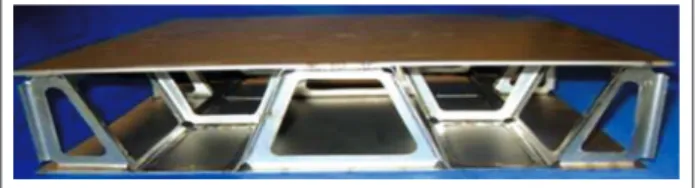
promising perspectives for application, since the light weight ibrous material guarantees excellent thermal insulation and the metallic frame increases structural strength (Fig. 1). Its main advantages are: highly eicient thermal insulation; very low maintenance; structural robustness; thermal and structural integration with the spacecrat main body. Nevertheless, for the correct design and sizing of such systems, some technical diiculties must be addressed: induced thermal stress due to the integration of diferent materials; balance between thermal and structural performance; deinition of the most appropriate material; construction and integration into the vehicle structure. herefore, the starting point for the optimization of a TPS structurally integrated is the knowledge about the thermo-structural behavior of both the structure and the insulating ibrous material working in a synergistic manner.
Several formulations to study heat transfer on insulating ibrous materials have been proposed (Raed and Gross, 2007), and several studies have been carried out towards modeling and optimizing the structural design of active thermal protection systems (Tamma and Thronton, 1987; Rakow and Wass, 2005). Nevertheless, combining insulating ibrous materials with metallic structural components of a TPS still requires investigations that could precisely predict the thermo-structural behavior of the system.
Figure 1. TPS structurally integrated.
his paper aims at developing a methodology for modeling the thermo-structural behavior of structural thermal protection systems and the application of such systems. Also, aims at applying an integrated methodology for modeling the thermo-structural behavior of TISSC, where the aerodynamic heating, heat transfer in porous insulation and thermo-structural analyses are coupled in sequence, which allows to obtain the temperature and the stress distribution for the whole trajectory of a vehicle, not only for particular instants or conditions like in the previously mentioned studies.
he proposed methodology is applied on sizing a structural thermal protection system for the SARA sub-orbital platform, a recovery sub-orbital vehicle that has been developed for microgravity experiments, in order to obtain the resulting performance and possible TPS mass reduction when compared with the conventional TPS originally designed.
MATHEMATICAL MODEL
AERODYNAMIC HEATING
To predict the heat transfer on SARA, it is necessary to know pressure, temperature and velocity ields around the vehicle. This can be accomplished by numerically solving the N-S equations. However, such a procedure is expensive and time-consuming. In the present work, a simpler, but reliable, engineering approach is also used. he following simplifying assumptions are made:
• Zero angle of attack.
• SARA rotation around its longitudinal axis is neglected.
• Atmospheric air is considered to behave as a calorically
and thermally perfect gas (no chemical reactions). he free stream conditions ahead of the nose cap are those
given by v∞, T∞, p∞, corresponding, respectively, to velocity,
temperature and pressure. By knowing v∞ and altitude, as function
of time, together with an atmospheric model (National Oceanic and Atmospheric Administration, 1976), it is possible to evaluate
the free stream properties, such as p∞, T∞, and c∞, which represent
For supersonic low (M∞ > 1), a detached shock wave appears ahead of the nose. By using the normal shock relationships, it is possible to calculate v1, T1 and p1 ater the shock.
he heat lux over the external surface was calculated through
the Zoby’s method (Zoby et al., 1981), namely:
where:
h: convective heat transfer coefficient; q: heat flux;
Tw: wall temperature.
he adiabatic wall temperature, Taw ,also called recovery
temperature, Tr , is given by:
where:
cp: specific heat at constant pressure; Te: temperature;
ve: velocity; e (subscript): refers to conditions at the boundary
layer edge; FR: recovery factor, equal to √Prw, for laminar low
and 3√Pr
w for turbulent low; Prw: Prandtl number evaluated
at wall temperature, Prw = 0.71.
he convective heat transfer coeicient comes from the Reynolds analogy, namely:
where:
a is equal to 0.6 for laminar low and 0.4 for turbulent low;
ρ: speciic mass.
To take into account compressibility efects, a modiied friction factor is obtained:
CF= K1(Reθ)K2 ρ*
e ρe μ
* e μe
K3
where:
K: thermal conductivity; μ: viscosity; *(superscript): refers
to properties evaluated at Eckert’s reference temperature
(Te*); Reθ: Reynolds number, based on the boundary layer
thickness (θ):
K1 1 N
(N + 1)(N + 2)
2
2N m
N + 1
C5
=
m = 2
N+ 1
Viscosity, μ, is evaluated according to Sutherland’s equation, as
function of temperature (Anderson, 1989). In Eq. 4, K1 = 0.44, K2 = –1
and K3= 1, for laminar low. For turbulent low, K2 = K3 = –m, and
For laminar low, the boundary layer thickness is given by:
θL 0.664 (∫ ρ*e μ*eveR2dy’)
ρeveR
1 2
=
y 0
where:
y (tangential coordinate) measured along the body’s
surface and y=0 corresponds to the stagnation point;
R: geometric parameter.
In this study, the numerical integration of Eq. 7 was obtained
according to the trapezoidal method. As R → 0, Eq. 7 becomes
undetermined. By taking the limit of Eq. 7 as R → 0, the following
expression is obtained:
0.332(ρ* e μ*e)
1 2
1 2 θL =
2(ps – p∞) 1
RN ps
In this study, Eq. 8 is applied for y < 0.1 RN, where RN is the curvature radius at the stagnation point.
he boundary layer thickness for turbulent low is obtained by solving the following irst-order diferential equation:
D (ρeveRθT)
Dy = 0.5 CF ρeveR
q = h (Taw – Tw)
C5= 2.2433 + 0.93N
N = 12.76 - 6.5log10(Reθ) + 1.21[log10(Reθ)]2
h = 0.5 ρecpvePrwCF
Taw = Te + FR
Reθ =
ve2
ρe ve θ
2cp
μe
(1)
(6c) (6b) (6a)
(6d)
(7)
(8)
(9) (3)
(4)
(5) (2)
-a
Ater obtaining the boundary layer momentum thickness,
θ, Reθ, CF and h can be evaluated by using Eqs. 5, 4 and 3,
and turbulent flow, the following relationship is used
(Zoby et al., 1981):
F(y) = 1 – exp – 0.412
(yT – yL) 4.74 (y – yL)
ρe,i = ρs pe,i ; he,i = hs ps
Te,i = he,i cp 1
γ pe,i
ps
γ – 1
γ ;
ve,i = √2(hs – he,i) ;
= 1 + 0.032M2
e,i + 0.58 – 1
T* e,i
Te,i
Tw
Te,i
ρc ∂T =
∂t kc
∂T ∂y ∂
∂y =
∂qr ∂y
''
where the subscripts Tr, L and T represent, respectively,
transitional, laminar and turbulent low. he transitional factor,
F(y), is given by:
Transition is supposed to occur for 163 < Reθ < 275.
Property evaluation at the boundary layer edge is performed assuming isentropic low between the stagnation region and
the location i, where properties are needed, namely:
he solution procedure can be summarized as follows:
• From a given trajectory, the US Standard Atmosphere
(National Oceanic and Atmospheric Administration, 1976) is used to obtain the free stream properties, including the stagnation ones.
• Normal shock relationships are used to obtain the luid
low properties behind the shock.
• By using the modified Newton method, pressure
distribution is obtained along the payload.
• Equation 12 provides the local properties at the
boundary layer edge.
• If y < 0.1 RN, Eq. 8 provides the laminar boundary layer
thickness, leading to the estimation of Reθ, CF and h,
provided by Eqs. 5, 4 and 3, respectively.
• If y > 0.1 RN and Reθ < 163, Eq. 7 is numerically integrated up to the location where the momentum thickness is to be estimated. Such an integration is performed by using the trapezoidal method.
• If y > 0.1 RN and Reθ> 275, Eq. 9 is numerically integrated by the trapezoidal rule leading to the turbulent boundary layer thickness.
• If y > 0.1 RN and 163 < Reθ < 275, Eqs. 10 and 11 are
used to estimate h.
It should be pointed out that such a procedure is performed
along the payload’s surface (following the y-coordinate), for
diferent trajectory times. herefore, h = h(y,t).
HEAt trAnsfEr in fibrOus insulAtiOn
Once the ilm coeicient and the external air temperature along the trajectory are known, the temperatures on the wall are calculated through the solution of the energy equation applied to the process of heat conduction on the TISSC system. Since the wall is made with aluminum, which has a high thermal difusivity, it can be treated as a one-dimensional problem along the wall thickness (Machado, 2006). Here, the thermo-physical properties of the system’s several layers must be known. For the insulating ibrous material inside the structural lattice, the heat conduction process involves: conduction through the ibers; conduction through the gases retained within the ibers’ voids; radiant heat exchange in participating media (iber and gases); and, possibly, some natural convection.
Environmental pressures varying from 1.33 x 10⁻⁵ to
101.32 kPa and temperatures varying from 300 to 1,300 K act on the insulating fibrous material. Most of the heat transfer models used for insulating ibrous materials have been validated through experimental results, obtained at limited intervals of pressure and temperature (Daryabeigi, 2003). he mathematical model herein applied (Daryabeigi, 2000, 2002, 2003; Daryabeigi
et al., 2006, 2007) considers heat transfer between two plates by combining the radiation and conduction modes. The insulating fibrous material between the plates is considered a articipating media. The main equation resulting from this approach is the one-dimensional energy conservation equation with an added source term for the radiant heat exchange. (11)
(12)
(13)
(14)
qTr= qL+ F(y)(qT– qL) (10)
where:
i: discrete position in which the parameter is calculated
along the surface. At the stagnation point, i = 1.
The local pressure, pe,i, is obtained from the modified
Newton method and γ = 1.4. The results of both methods
are then compared. he subscript s appearing in Eq. 12 refers
he solid conduction term, ks, is extracted from an empirical
model based on density and thermal conductivity, k, of bulk
material: where:
ρc = ρcp; kc: thermal conductivity of the solid; r (subscript): related to radiation.
he equivalent thermal conductivity model, for the porous media, was validated through Daryabeigi’s experimental results (Daryabeigi, 2003) and a modiied version of the model described
in this work, proposed by Machado (2014), which used Sail®
(alumina iber) as the porous media.
For an optically thick medium, the difusion approximation can be used, resulting in the radiant heat lux of:
qr –k
r
= ∂T
∂y
''
Using this approximation, the energy equation reduces to:
ρc = keff ∂T
∂y ∂
∂y ∂T ∂t
where:
kef : apparent or efective thermal conductivity.
kef is obtained by superposition of the thermal conductivities
due to solid conduction, gas conduction, and radiation:
kr=16 σ n*2T3
3ρe
β 2 - α α
= 2γ
2γ + 1
Kn λ
LC =
Φ + Ψ Kn
kg = β
Pr kg0 (T)
where:
Ф = 1, ψ = 0 for Kn < 0.01 (continuum regime); Ф = 1,
ψ = 1 for 0.01 < Kn < 10 (transition regime); Ф = 0, ψ = 1 for
Kn > 10 (free-molecular regime); and β:
where:
a: thermal accommodation coeicient; γ: gas speciic heat
ratio; Kn: Knudsen number, being:
(15)
(16)
(17)
(20a)
(20b)
(21) (18)
(19)
kef = kr + ks + kg
ks (T) = Fsfvb k s
* (T), 1 ≤ b ≤ 3
where:
kr: radiant thermal conductivity for ibrous insulations;
ks: solid conduction term; kg: thermal conductivity of the gas.
he radiant thermal conductivity for ibrous insulations,
kr, is provided by:
where:
σ: Stefan-Boltzman constant (5.670 x 10⁻⁸ W/m2K4);
e: speciic extinction coeicient, estimated from the experimental
data using a genetic algorithm-based parameter estimation
technique; n*: efective index of refraction.
A curve it of the efective index of refraction with iber volume
fraction was used. he optical thickness is given by τ = ρeL, where
L is the thickness of the ibrous insulation. he insulation can
be considered optically thick only if τ > > 1, which is valid for
insulation samples used in this study with optical thickness > 20.
where:
Fs: factor relating microscale geometric effects of fiber
matrix and bulk dimensions. It is obtained from steady state measurements in vacuum and at cryogenic temperatures (test condition with negligible gas conduction and reduced radiation);
B: constant not known a priori; fv: volume fraction.
he heat conduction is considered to occur in the porous media, as a combination of solid and gas conduction processes. he solid conduction occurs through the ibrous, and its thermal conductivity dependence on temperature is considered to be well-known.
According to statistic thermodynamics, gas thermal conductivity is supposed to depend only on the temperature and to be independent on the pressure. However, in a porous media, it was veriied that pressure plays an important role below a certain level.
he current model uses a classical approach to estimate the gas thermal conductivity inside the ibrous, based on the Knudsen hypothesis. he standard temperature function used
to estimate the gas thermal conductivity, kg0(T), is corrected
where:
l: molecular mean free path of the gas; LC: characteristic
length of the ibrous insulation.
his model does not include the possibility of heat convection within the ibrous insulation. However, in microscale, it is remarkable that the two phases of the porous media, ibers and gas, have diferent optical properties. he gas is considered to be transparent, and the solid ibers approach to the behavior of a black body. Indeed, any radiative heat transfer to the media will cause diferent heating in each phase, and the temperature reached in the ibers tends to be higher than in the gas. his diference will depend on several parameters, but no matter how small, it can cause a local heat exchange by natural convection between the iber and the gas. Since it occurs in microscale, as soon as the heated gas gets far from the iber surface, it mixes with the bulk gas around, reaching thermal equilibrium and ceasing the natural convection. he distance traveled by the gas until stopping may correspond to a few iber diameters. It means that the process occurs continuously in the domain and it is as homogeneous as the iber distribution, approaching a difusion process. his hypothesis explains the fact that the values found for this parameter in the experimental tests are higher than the theoretical ones in the majority of the works; this diference appears and rises with the pressure increasing. When this efect is accounted, the efective thermal conductivity is better represented by:
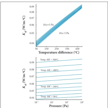
Figure 2. Results for Keq as function of pressure and temperature difference.
Temperature difference (oC)
Pressure (Pa) 50
10-1 0.04 0.06
0.05 0.08
0.07 0.09 0.04
Temp. diff. = 500oC
Temp. diff. = 400oC
Temp. diff. = 200oC
Temp. diff. = 50oC 0.06
0.05 0.08
0.07 0.09
10.e+5 Pa
10.e-5 Pa
101 103 105
150 250 350 450
Keff
(W/m.
oC)
Keff
(W/m.
oC) where:
D: iber diameter.
A detailed model for obtaining h and the comparison between
the original and modiied models, showing the improvements of the new model when compared with experimental results, were presented by Machado (2014).
According to this model, the variation of kef as function of
pressure and temperature diference between the plates (with a lower temperature of 60°C, which is the limit for the internal surface) is showed in Fig. 2.
Both variations can be itted by the following function:
where:
a = 0.001884858198 and b = 0.03446775065.
where:
ρ is the density of the porous material. In this work, ρ was
considered to be 24.2 kg/m3.
(22)
(24)
(25)
(26)
(23a)
(23b)
(23c)
kef = kr + ks+ (1 – f)(kg + hD)
cpair= 1027.582 – 0.2216T + 4.561 x 10⁻⁴ T 2 +
2.455 x 10⁻⁷ T 3 – 16.643 x 10⁻¹⁰ T 4 + 3.616 x 10⁻¹³ T 5 –
6.349 x 10⁻¹⁷ T 6
Kair= –1.8763 x 10⁻³ + 1.218 x 10⁻⁴ T– 1.328 x 10⁻² T 2
+ 1.479 x 10⁻¹⁰ T 3 – 18.58 x 10⁻¹⁴ T 4 + 1.705 x 10⁻¹⁷ T 5
+ 9.527 x 10⁻²² T 6
Ks= (1.63 x 10⁻⁵ – 2.114 x 10⁻⁸ T+ 1.131 x 10⁻¹¹ T 2 –
2.094 x 10⁻¹⁵ T 3) x ρ
kef (ΔT, P) = F(P)G(ΔT)
G(ΔT) = beaΔT
F(P) = bPa
where:
a = 0.005102720025 and b = 0.03910708429. his function
allows obtaining an overall rms error of 1.33% when compared
to the model results.
structurAl AnAlYsis
he structural model studied is presented in Fig. 3. he void regions are illed with the insulating ibrous material. A 3-D inite element model, with tetrahedron elements, is used to evaluate temperature distribution, displacements, strains and stress on
the structure by using the inite element sotware ABAQUS®.
he model’s upper plate represents the vehicle’s wall external surface receiving the aerodynamic heating. On the other hand, the lower plate represents the vehicle’s internal region which must maintain the temperatures deined by the design (60°C). he heat lux, temperatures and thermal conductivities calculated with the aerodynamic heating and heat conduction models, respectively, are then applied on the structural model resulting in displacements, strains, stresses, and temperature distributions at each point within the structure.
RESULTS
he sub-orbital platform SARA was initially selected for the studies using the methodology presented in this work. Sub-orbital platforms are low cost alternatives for microgravity research. SARA’s total mass will be of the order of 250 kg with a payload mass of about 25 kg, and it will provide 6 minutes of micro-gravity environment. SARA may reach speeds of 9,300 km/h in atmospheric light. A future orbital version of SARA may reach an orbit of 300 km and an orbital period of 10 days (Moraes Jr., 1998).
Figure 4a shows SARA’s lateral thermal protection system in its original coniguration. A structural aluminum wall 4 mm thick is covered with a 6 mm thick cork layer applied all over the vehicle’s conical region. A new coniguration,
Figure 3. TISSC structural model without (top) and with (bottom) the upper plate.
4 mm Al wall 18 mm
1 mm Al plates Saffil fulfillment 6 mm cork layer
Figure 4. SARA’s thermal protection systems. (a) Original coniguration; (b) proposed coniguration.
similar to the one shown in Fig. 1, is proposed. he system is a sandwich structure composed of two 1 mm thick aluminum
walls illed with an 18 mm layer of Sail®, shown in Fig. 4b.
he total thickness variation is compatible with the geometry of the spherical cap at the top.
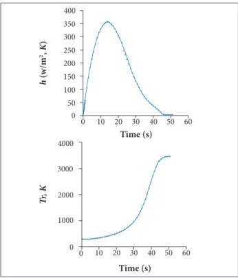
The aerodynamic parameter (h and TR) calculations
presented by Machado (2012) showed results with slight variations along the conical region. Thus, average values at the conical region for the convection heat transfer
coefficient h(t) and the recovering temperature Tr (t), during
the ascending trajectory, were used in this work. Figure 5 shows both curves.
1000 2000 3000 4000 50 100 150 200 250 300 350 400
0
0
h
(w/m
2,
K
)
Tr
, K
Time (s)
Time (s)
0 10 20 30 40 50 60
0 10 20 30 40 50 60
Figure 5. Average values of h(t) and Tr(t) at SARA’s conical region.
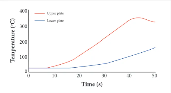
Figure 7. Resulting temperatures on the upper and lower plates.
Figure 8. Temperature distribution (K) at time = 50 s.
*Dependent on temperature and pressure.
+6.045e + 02 +5.897e + 02 +5.748e + 02 +5.600e + 02 +5.452e + 02 +5.303e + 02 +5.155e + 02 +5.006e + 02 +4.858e + 02 +4.710e + 02 +4.561e + 02 +4.413e + 02 +4.265e + 02
Figure 6. The inite element mesh — front view.
Table 1. Material properties.
Property
Material
Aluminum safil®
Young’s modulus - E (GPa) 70 3.0 x 10⁻⁶
Mass density r (kg/m3) 2,700 24.2
Speciic heat (J/kg°C) 960 1,005
Poisson’s ratio (n) 0.3 0.4
hermal expansion coeicient 2.0 x 10⁻⁵ 8.0 x 10⁻⁶
hermal conductivity (W/m°C) 177 *
of the system. Nevertheless, this problem may be solved by using different materials for each component, with the inner structure working as heating insulators. A possibility will be the use of composites for those members.
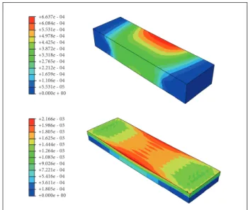
he thermal protection system currently proposed to be used on the SARA platform (Fig. 4a) and the one proposed in this study (Figs. 4b and 6) had their load carrying capabilities compared. For both designs with the same lateral dimensions as those on Fig. 6, the present model shows a mass reduction of 7.6%. Figures 11 and 12 show displacements and stress results, respectively, when the structure is subjected to an external pressure of 5 atmospheres (maximum dynamic pressure during the light). he present model shows a reduction in displacements of 30% and an increase in stress of 62.3%. However, it is important to note that linear tetrahedron elements present very poor stress results, and thus the actual values may be quite diferent than the ones obtained. Nevertheless, the displacement results are precise enough, and the aim of the present work is not to obtain accurate results for stresses, but to study only both models’ load carrying capabilities. he results clearly indicate the proposed design’s high stifness. Obviously, there is still margin to reduce the model stifness, further reducing the total mass of the whole structural system.
0
Time (s)
T
emp
er
at
u
re
(
oC)
0
10 20 30 40 50
100 200 300
400 Upper plate
Lower plate A inite element model using 77,604 tetrahedron elements
C3D4T (ABAQUS®) and approximately 15 thousand nodal
points was employed in the analyses. Figure 6 shows a section of the mesh, where the red dots indicate nodes with
constrained translations in the x, y, and z directions. A constant
load of 5 atmospheres, corresponding to the maximum dynamic pressure, was applied to the structure. As initial condition, the entire structure is subjected to the temperature of 300 K. he boundary conditions for temperature were Eq. 1 for external surface and adiabatic wall for internal surface. Material properties are presented in Table 1.
Figure 7 brings temperature results for the upper and lower plates. The inner structures connecting the plates work as a heat conductor, thus decreasing the upper external plate temperature and increasing the temperature on the internal lower plate at contact regions. None of the carried out analyses took into account property variations with temperature, as strength and stiffness. Only the values of the
thermal conductivity property of the filling fibrous Saffil®
were considered as varying with temperature.
Figure 11. Displacements for each model.
Figure 12. Stresses distributions.
Figure 9. Temperature distribution (K) at time = 50 s on the aluminum structure.
Figure 10. Temperature distribution (K) at time = 50 s on the Safil® ibers.
+6.045e + 02 +5.898e + 02 +5.751e + 02 +5.604e + 02 +5.458e + 02 +5.311e + 02 +5.164e + 02 +5.017e + 02 +4.870e + 02 +4.723e + 02 +4.576e + 02 +4.430e + 02 +4.283e + 02
+6.045e + 02 +5.896e + 02 +5.748e + 02 +5.600e + 02 +5.451e + 02 +5.303e + 02 +5.155e + 02 +5.006e + 02 +4.858e + 02 +4.710e + 02 +4.561e + 02 +4.413e + 02 +4.265e + 02
+1.842e + 08 +1.689e + 08 +1.535e + 08 +1.382e + 08 +1.229e + 08 +1.075e + 08 +9.221e + 07 +7.688e + 07 +6.155e + 07 +4.622e + 07 +3.089e + 07 +1.556e + 07 +2.309e + 05
+1.135e + 08 +1.041e + 08 +9.467e + 07 +8.524e + 07 +7.581e + 07 +6.638e + 07 +5.695e + 07 +4.752e + 07 +3.808e + 07 +2.865e + 07 +1.922e + 07 +9.791e + 06 +3.600e + 05
+6.637e - 04 +6.084e - 04 +5.531e - 04 +4.978e - 04 +4.425e - 04 +3.872e - 04 +3.318e - 04 +2.765e - 04 +2.212e - 04 +1.659e - 04 +1.106e - 04 +5.531e - 05 +0.000e + 00
+2.166e - 03 +1.986e - 03 +1.805e - 03 +1.625e - 03 +1.444e - 03 +1.264e - 03 +1.083e - 03 +9.026e - 04 +7.221e - 04 +5.416e - 04 +3.611e - 04 +1.805e - 04 +0.000e + 00
CONCLUSION
his study shows the development of a model to study the thermo-structural behavior of a hermally Integrated Structural Sandwich Core (TISSC) for spacecrat. Aerodynamic heating and heat conduction processes in a porous media, temperature and pressure dependent, were evaluated by previously developed and validated methodologies. A proposed design is then used for thermo-structural analyses through the inite element method. he results obtained for the proposed model and a previously designed thermo-protection system are compared. Although promising, the results have shown that the system requires further improvement, as to avoid the reinforcing structural components to behave as heat conducting elements, thus negatively afecting the insulating capability of the system. Results have also shown the high stifness of the proposed design, in terms of its load carrying capabilities, which may be optimized and thus engender expressive mass reduction for the entire model. herefore, although some limitations were observed in the proposed TPS, the results
presented have illustrated very well the potentiality of the employed methodology.
ACKNOWLEDGEMENTS
REFERENCES
Anderson Jr., J.D., 1989, “Hyphersonic and High Temperature Gas Dynamics”, McGraw-Hill, New York, USA.
Da Costa, L.E.V.L., De Mello, F.C. and Pardini, L.C., 1996, “Viability Study of Thermal Protection for SARA Platform”, IAE/CTA, Technical note NT-130-ASE-N/96, IAE/CTA, São José dos Campos, Brazil (in Portuguese).
Daryabeigi, K., 2000, “Design of High Temperature Multi-Layer Insulation for Reusable Vehicles”, Ph.D. Thesis, University of Virginia, Charlottesville, USA.
Daryabeigi, K., 2002, “Thermal Analysis and Design Optimization of Multilayer Insulation for Reentry Aerodynamic Heating”, Journal of Spacecrafts and Rockets, Vol. 39, No. 4, pp. 509-514. doi: 10.2514/2.3863
Daryabeigi, K., 2003, “Heat Transfer in High Temperature Fibrous Insulation”, Journal of Thermophysics and Heat Transfer, Vol. 17, No. 1, pp. 10-20. doi: 10.2514/2.6746
Daryabeigi, K., Cunnington, G.R. and Knutson, J.R., 2007, “Measurements of Heat Transfer in Unbounded Silica Fibrous Insulation and Comparison with Theory”, Proceedings of the 29th International Thermal Conductivity Conference, Birmingham, USA.
Daryabeigi, K., Miller, S.D. and Cunnington, G.R., 2006, “Heat Transfer in High-Temperature Multilayer Insulation”, ESA – TPS & Hot structures. Retrieved in March 25, 2015, from http://develop. nttc.edu/sbipp/technologyportfolios/portfolios/LCRATSATPS/ Archive%5C20080013560.pdf
Machado, H.A., 2006, “Thermal Protection for Aerodynamic Heating in the SARA Sub-orbital Platform”, Proceedings of the IV National Congress of Mechanical Engineering – CONEM, Recife, Brazil (in Portuguese).
Machado, H.A., 2009, “Two-Dimensional Simulation of Multi-Layer Ablation-Conduction Problem in a Rocket TPS via an Interface Tracking Method”, Proceedings of the 41st AIAA Thermophysics Conference, San Antonio, USA.
Machado, H.A., 2012, “Two-Dimensional Simulation of Ablation due to Aerodynamic Heating in the SARA Sub-Obital Platform”, High Temperatures. High Pressures. Retrieved in March 25, 2015, from http://www.oldcitypublishing.com/journals/hthp-home/hthp-issue-contents/hthp-volume-41-number-4-2012/hthp-41-4-p-255-271/
Machado, H.A., 2014, “Modeling Heat Transfer with Micro-Scale Natural Convection in Fibrous Insulation”, Journal of the Brazilian Society of Mechanical Sciences and Engineering, Vol. 36, No. 4, pp. 847-857. doi: 10.1007/s40430-013-0107-x
Machado, H.A. and Pessoa-Filho, J.B., 2007, “Aerodynamic Heating at Hypersonic Speeds”, COBEM 2007, Brasília, Brazil.
Moraes Jr., P., 1998, “Design Aspects of the Recoverable Orbital Platform SARA”, Proceedings of 8th Chilean Congress of Mechanical Engineering, Concepcíon, Chile.
National Oceanic and Atmospheric Administration, 1976, “U.S. Standard Atmosphere, 1976”, U.S. Government Printing Ofice, Washington, USA.
Pessoa Filho, J.B., Genaro, G., 2006, “Simulation of a Multilayer Thermal Protection System Submitted to Conditions Representative of Atmospheric Reentry”, Proceedings of the 57th International Astronautical Congress, Valência, Spain.
Poteet, C.C., Abu-Khajeel, H. and Hsu, S.Y., 2004, “Preliminary Thermal-Mechanical Sizing of a Metallic Thermal Protection System”, Journal of Spacecraft and Rockets, Vol. 41, No. 2, pp. 173-182. doi: 10.2514/1.9174
Raed, K. and Gross, U., 2007, “Review on Gas Thermal Conductivity in Porous Materials and Knudsen Effect”, Proceedings of the 29th International Thermal Conductivity Conference, Birmingham, USA.
Rakow, J.F. and Wass, A.M., 2005, “Thermal Buckling of Metal Foam Sandwich Panels for Convective Thermal Protection Systems”, Journal of Spacecraft and Rockets, Vol. 42, No. 5, pp. 832-844. doi: 10.2514/1.9741
Rogan, J.E. and Hurwicz, H., 1973, “High-temperature Thermal Protection Systems”, In: Rohsenow, W.M., Hartnett, J.P. and Cho, Y.I. (Eds.), Handbook of Heat Transfer, McGraw-Hill, New York, USA.
Tamma, K.K. and Thornton, E.A., 1987, “Re-Entry Thermal/Structural Finite-Element Modeling/Analysis of Shuttle Conigurations”, Journal of Spacecraft and Rockets, Vol. 24, No. 2, pp. 101-108.