American Journal of Applied Sciences 10 (8): 853-856, 2013 ISSN: 1546-9239
©2013 Science Publication
doi:10.3844/ajassp.2013.853.856 Published Online 10 (8) 2013 (http://www.thescipub.com/ajas.toc)
853
Science Publications AJAS
EFFECT OF THE SCREW TORQUE
LEVEL ON THE INTERFRAGMENTARY
STRAIN AND THE INTERFRAGMENTARY MODULUS
Boonthum Wongchai
Department of Mechanical Engineering, Faculty of Engineering at Si Racha, Kasetsart University, 199 M.6, Tungsukhla, Si Racha, Chonburi, 20230, Thailand
Received 2012-12-30, Revised 2013-05-22; Accepted 2013-07-13
ABSTRACT
The screw torque is applied at the screw head to fix the plate and the bone. It generates the compressive force between the plate and the bone to stabilize them. The interfragmentary strain is the main factor for healing the bone fractured. The screw torque level affects the interfragmentary strain and the stability of the fixation between the plates an the bone. The interfragmentary modulus is the new factor of the plate fixation stability and it is affected by the torque level. This research is proposed to study the effect of the screw torque level on the interfragmentary strain and the interfragmentary modulus. The interfragmentary strain and the interfragmentary modulus decrease by increasing the screw torque level.
Keywords: Screw Torque Level, Interfragmentary Strain, Interfragmentary Modulus, LC-DCP, Limited Contact Dynamics Compression Plate, Femur Fracture
1. INTRODUCTION
Internal fixation is the main method to cure the human bone fracture (Wahnert et al., 2012). The plate fixation is the main choice of the internal fixation. The Dynamic Compression Plate (DCP) and the Limited Contact Dynamics Compression Plate (LC-DCP) are generally used to fix the broken bone. For the DCP, only the conventional screws are used. The conventional screws fix the plate and the bone by the compressive force that is generated by the applied torque at the screw head (Kanchanomai et al., 2008; Field et al., 2004; Kabak et al., 2004; Gao et al., 2011; Kumar et al., 2013). For the LC-DCP, the locking screws are used to make the distance between plate and bone. The conventional screw can be used in the LC-DCP as the DCP.
The contact between the plate and the femur affects the periosteal blood supply to the femur (Haasnoot et al., 1995; Ahmad et al., 2007). The LC-DCP is developed to solve this problem by using the locking screws (Borgeaud et al., 2000; Field et al., 2004; Kabak et al., 2004; Miller and Goswami, 2007).
However, the stability of the plate and the bone must be conscious. The plate fixation with the conventional screws has more stable than the locking
screws because the locking screw cannot generates the compressive force (Haasnoot et al., 1995; Ahmad et al., 2007; Kumar et al., 2013).
In the human bone fracture, the screw tensile force (internal force) ranges from 2000 N to 3000 N (Kim et al., 2010). Ahmad et al. (2007) applied the screw torque of 4 N⋅m in their research.
The interfragmentary strain (εIF) is a main factor of
femur fractured healing. It has the best ranges from 2-10% (Perren, 1979; Kim et al., 2010). It is defined as the ratio of the fracture gap displacement after the body load applied and the original fracture gap as shown in Fig. 1.
The Equation (1) of εIF is:
IF
L
ε =
L (1)
∆L = The fracture gab displacement after the body load (W) applied
L = The original fracture gap length (L = 10 mm for this study)
Boonthum Wongchai / American Journal of Applied Sciences 10 (8): 853-856, 2013
854
Science Publications AJAS
The normal stress in the plate at the fracture gab is the combine stress from the normal stress and the bending stress (Fouad, 2011). For the normal stress, the equation of the normal stress can be written as Equation (2):
IF
W
σ =
A (2)
Where:
σIF = Normal stress or interfragmentary stress W = Body load
A = Plate cross section area
The equation of the bending stress is Equation (3):
b
My
σ =
I (3)
M = Bending moment = We (e = distance from the body load to the centroid of the plate cross section area)
σb = Bending stress
y = The distance from the centoid of the plate cross section area
I = Moment of inertia of the plate cross section area
Wongchai (2012) has defined the Interfragmentary Modulus (IM) as the slope of the graph between σIF and εIF when the are linearity related. The relation between σIF and
εIF can be written as Equation (4):
IF IF
σ = IMε + k (4)
k = Constant value
In the present work, the interfragmentary strain and the interfragmentary modulus is the goal to study at various bone screw torques level.
Fig. 1. The deformation of the fractured femur
2. MATERIALS AND METHODS
The 3406 large left fourth generation femur of Pacific Research Lab is used in the present work. The Pacific research laboratories bone are usually used in biomechanics research (Greer and Wang, 1999; Stoffel et al., 2003; Ahmad et al., 2007). The 12-holes LC-DCP from synthes Inc. with the ten conventional screws are attached on the femur.
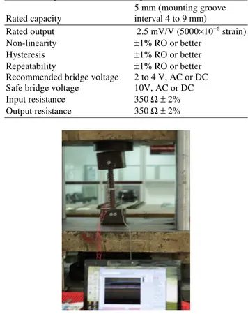
The 10 mm gap is generated at the middle point of the femur. The Kyowa DTC-A-5 clip-type displacement transducer with specification listed in
Table 1 is used to measure ∆L.
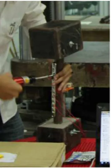
The lowest of the femur is fixed with epoxy resin while the femur head is fixed by one bolt as shown in Fig. 2.The jig at the femur head can be rotated about this bolt and touched the femur head for transferring the compressive force from the compressive testing machine.
The compressive force from the compression testing machine and displacement signals are converted to digital signals by the Kyowa PCD-300A. The PCD-300A software is used for data recording.
Table 1. Displacement transducer specification
5 mm (mounting groove Rated capacity interval 4 to 9 mm)
Rated output 2.5 mV/V (5000×10−6 strain) Non-linearity ±1% RO or better
Hysteresis ±1% RO or better Repeatability ±1% RO or better Recommended bridge voltage 2 to 4 V, AC or DC Safe bridge voltage 10V, AC or DC Input resistance 350 Ω± 2% Output resistance 350 Ω± 2%
Boonthum Wongchai / American Journal of Applied Sciences 10 (8): 853-856, 2013
855
Science Publications AJAS
Fig. 3. The bone screw torque setting
Figure 3 shows the torque applyed on the screw head. The level of the screw torque is varies from 1 to 5 N.m. The compressive force F on the femoral head is varies from 0 to 300N.
3. RESULTS
The graphs of εIF versus the compressive force for all
cases of the screw torque level are shown in Fig. 4. By using the Equation (2) and (4), the graphs of σIF versus εIF for all cases of the screw torque level are
shown in Fig. 5.
The relations between εIF and F are generated by
using the linear regression in Equation (5):
IF
ε = aF + b (5)
Where: a, b = Constant
The results of a and b with R2 are in Table 2. By using Equation (4), IM and k are calculated and shown in Table 3.
4. DISCUSSION
From Fig. 4, it has been found that the slopes of the graph decreased by increasing the screw torque level. In other words; for the same compressive force applied at the femoral head, the interfragmentary strain decreased when the screw torque level is increased.
From the data in Table 2, It has been seen that the relation between εIF and F is the linear function with high
R2 because the plate, the femur and the screws are linear materials. In the present work, the applied force at the femur head is not exceeding the elastic limit of all parts.
Fig. 4. The correlation between εIF and F
Fig. 5. The correlation between and εIF
Table 2. Correlation constants for ε IF
Bone screw torque
(N.m) a b R2
1 0.00154 0.00613 0.993 2 0.00206 0.00589 0.996 3 0.00322 0.00463 0.999 4 0.00415 0.00397 0.999 5 0.00507 0.00356 0.999
Table 3. IM and k Bone screw torque
(N.m) IM k R2
Boonthum Wongchai / American Journal of Applied Sciences 10 (8): 853-856, 2013
856
Science Publications AJAS
The graphs of the εIF and F must be stayed in the elastic
zone of material (linear zone).
Table 3 shows that the relations between σIF and εIF
are linear with high R2. The slope (IM) of the graphs in
Fig. 5 decreased when the screw touque level is increased. Because the meaning of IM is the spring stiffness and the stabilliy of the bone-plate fixation. Thus, the stabilliy of the bone-plate fixation decresed when the screw touque level is increased.
5. CONCLUSION
• The interfragmentary strain decreased by increasing the screw torque level
• The interfragmentary modulus decreased by increasing the screw torque level
6. ACKNOWLEDGEMENT
The researcher is grateful to Kasetsart University, Si Racha Campus and the Center for Advanced Studies in Industrial Technology for the research grants.
7. REFERENCES
Ahmad, M., R. Nanda, A.S. Bajwa, J. Candl-Couto and S. Green et al., 2007. Biomechanical testing of the locking compression plate: When does the distance between bone and implant significantly reduce construct stability? Injury, 38: 358-364. DOI: 10.1016/j.injury.2006.08.058
Borgeaud, M., J. Cordey, P.F. Leyvraz and S.M. Perren, 2000. Mechanical analysis of the bone to plate interface of the LC-DCP and of the PC-FIX on human femora. Injury, 31. 29-36. PMID: 11052378 Field, J.R., R. Edmonds-Wilson and R.M. Stanley, 2004.
An evaluation of interface contact profiles in two low contact bone plates. Injury, 35: 551-556. DOI: 10.1016/S0020-1383(03)00215-8
Fouad, H., 2011. Assessment of function-graded materials as fracture fixation bone-plates under Combined loading conditions using finite element modelling. Med. Eng. Phys., 33: 456-463. DOI: 10.1016/j.medengphy.2010.11.013
Gao, M., W. Lei, Z. Wu, D. Liu and L. Shi, 2011. Biomechanical evaluation of fixation strength of conventional and expansive pedicle screws with or without calcium based cement augmentation. Clin.
Biomech., 26: 238-244. DOI:
10.1016/j.clinbiomech.2010.10.008
Greer, B. and E.L. Wang, 1999. Solid model in IGES format.
Haasnoot, E.V.F., T.W.H. Miinch, P. Matter and S.M. Perren, 1995. Radiological sequences of healing in internal plates and splints of different contact surface to bone. (DCP, LC-DCP and PC-Fix). Injury, 26: B28-B36. DOI: 10.1016/0020-1383(95)96896-C
Kabak, S., M. Halici, M. Tuncel, L. Avsarogullari and S. Karaoglu, 2004. Treatment of midclavicular nonunion: Comparison of dynamic compression plating and low-contact dynamic compression plating techniques. J. Shoulder Elbow Surgery, 13: 396-403. DOI: 10.1016/j.jse.2004.01.033
Kanchanomai, C., V. Phiphobmongkol and P. Muanjn, 2008. Fatigue failure of an orthopedic implant-A locking compression plat. Eng. Failure Anal., 15: 521-530. DOI: 10.1016/j.engfailanal.2007.04.001 Kim, S.H., S.H. Chang and H.J. Jung, 2010. The finite
element analysis of a fractured tibia applied by composite bone plates considering contact conditions and time-varying properties of curing tissues. Compos. Struct., 92: 293-2118. DOI: 10.1016/j.compstruct.2009.09.051
Kumar, V., D. Mehrotrab, S. Mohammadc, R.K. Singhb and V. Singhd et al., 2013. Anchor lag screw vs conventional lag screw in mandibular fractures: A series of 30 cases. J. Oral Biol. Craniofacial Res., 3: 15-19. DOI: 10.1016/j.jobcr.2013.01.002
Miller, D.L. and T. Goswami, 2007. A review of locking compression plate biomechanics and their advantages as internal fixators in fracture healing. Clin. Biomech., 22: 1049-1062. DOI: 10.1016/j.clinbiomech.2007.08.004
Perren, S.M., 1979. Physical and biological aspects of fracture healing with special reference to internal fixation. Clin. Orthop. Relat. Res., 138: 175-196. PMID: 376198
Stoffel, K., U. Dieter, G. Stachowiak, A. Gachter and M.S. Kuster, 2003. Biomechanical Testing of the LCP- how can stability in locked internal fixators be controlled? Injury, 34: 11-19. DOI: 10.1016/j.injury.2003.09.021
Wahnert, D., J.H. Lange, M. Schulze, S. Lenschow and R. Stange et al., 2012. The potential of implant augmentation in the treatment of osteoporotic distal femur fractures: A biomechanical study. Injury, 44: 808-812. DOI: 10.1016/j.injury. 2012.08.053 Wongchai, B., 2012. Interfragmentary modulus. Am. J.
Applied Sci., 9: 372-375. DOI: