Rogério Pirk*
Institute of Aeronautics and Space São José dos Campos – Brazil [email protected]
Carlos d’Andrade Souto
Institute of Aeronautics and Space São José dos Campos – Brazil [email protected]
Dimas Donizeti da Silveira
Institute of Aeronautics and Space São José dos Campos – Brazil [email protected]
Cândido Magno de Souza
Institute of Aeronautics and Space São José dos Campos – Brazil [email protected]
Luiz Carlos Sandoval Góes
Technological Institute of Aeronautics São José dos Campos – Brazil [email protected]
*author for correspondence
Liquid rocket combustion
chamber acoustic characterization
Abstract: Over the last 40 years, many solid and liquid rocket motors have experienced combustion instabilities. Among other causes, there is the interaction of acoustic modes with the combustion and/or luid dynamic processes inside the combustion chamber. Studies have been showing that, even if less than 1% of the available energy is diverted to an acoustic mode, combustion instability can be generated. On one hand, this instability can lead to ballistic pressure changes, couple with other propulsion systems such as guidance or thrust vector control, and in the worst case, cause motor structural failure. In this case, measures, applying acoustic techniques, must be taken to correct/minimize these inluences on the combustion. The combustion chamber acoustic behavior in operating conditions can be estimated by considering its behavior in room conditions. In this way, acoustic tests can be easily performed, thus identifying the cavity modes. This paper describes the procedures to characterize the acoustic behavior in the inner cavity of four different conigurations of a combustion chamber. Simple analytical models are used to calculate the acoustic resonance frequencies and these results are compared with acoustic natural frequencies measured at room conditions. Some comments about the measurement procedures are done, as well as the next steps for the continuity of this research. The analytical and experimental procedures results showed good agreement. However, limitations on high frequency band as well as in the identiication of speciic kinds of modes indicate that numerical methods able to model the real cavity geometry and an acoustic experimental modal analysis may be necessary for a more complete analysis. Future works shall also consider the presence of passive acoustic devices such as bafles and resonators capable of introducing damping and avoiding or limiting acoustic instabilities.
Keywords: Combustion chamber, Combustion instability, Acoustic resonance, Liquid rocket engine (LRE).
INTRODUCTION
Combustion instabilities have been present in the development of liquid rocket engines (LRE) over the last decades. There are basically three types of combustion instabilities in LRE: low frequency, medium frequency and high frequency. Low frequency instabilities, also called chugging, are caused by pressure interactions between the propellant feed system and the combustion chamber. Medium frequency instabilities, also called buzzing, are due to coupling between the combustion
process and the propellant feed system low. The high
frequency instabilities are the most potentially dangerous and not well-understood ones. It occurs due to coupling of the combustion process and the chamber acoustics (Sutton and Biblarz, 2001).
The presence of acoustic (high frequency) combustion instabilities shall be considered still in development
phase, although only after real iring tests combustion instabilities can be clearly identiied.
Combustion chambers environments present high levels of acoustic noise. Bunrley and Culick (1997) described
that this can be veriied when the power spectrum of the
acoustic pressure levels, measured during burning tests of the chambers, is analyzed. When an oscillation is observed, i.e., combustion instability, sound pressure peaks with
well-deined magnitudes summed to the background noise
are present. These peaks are correlated with the resonance frequencies of the combustion chambers cavities, where
the sound pressure on each position of the acoustic luid
space represent the environment oscillation, attributed to the acoustic modes of these cavities. Such a way occurs the coupling of the acoustic natural frequencies and the burning oscillations of the combustion chamber, which can cause instabilities and consequent unexpected behavior
such as eficiency loss or even explosion of the engine.
A LRE combustion chamber has longitudinal, tangential and radial acoustic modes. Coupled modes combining
Received: 14/09/10 Accepted: 20/10/10
these types are also possible to occur. The tangential and radial modes are the most dangerous to high frequency instabilities (Yang, Wicker and Yoon, 1994). The three basic types of acoustic modes of a cylinder representing a LRE combustion chamber are shown in Fig. 1.
changing these parameters, one can obtain a design less susceptible to this kind of instabilities (Huzel and Huang, 1992). Also, passive acoustic devices for the attenuation
of acoustic noise, as Helmholtz resonators, liners, bafles and ¼ wave ilters can be introduced in the combustion
chamber (Santana Junior et al., 2009).
It is important to mention that, in the latter stages of this survey, numerical methods for modeling acoustics of chambers as well as insulation treatments for attenuating acoustic noises will be presented. Currently, only
comparisons between theoretical versus experimental
results, using simple mathematical models and measured frequency response functions, respectively, are carried out
for different conigurations of a combustion chamber.
OBJETIVE
The objective of this work was to present the adopted procedures for the dynamic characterization of different
conigurations of combustion chamber models for a liquid
rocket engine capable of generating 75 kN thrust. The models were built on aluminum, in 1:1 scale. In order to assess the
inluence of the chamber geometry on the chamber acoustic
behavior, the referred combustion chamber models were segmented. This segmentation allowed us analyzing the
inluence of the different lengths on the dynamic behavior
of the acoustic environment. It is worth mentioning that the tests were performed under room environmental conditions, without simulating the pressure and temperature conditions during the combustion of a rocket engine.
Hereinafter, the measurement procedures to obtain the
acoustic parameters of different conigurations of the 75
kN combustion chamber, as well as the method applied for the calculation of the theoretical natural frequencies were presented. Measuring setup, collected data and the applied criteria for the choice of FRF were described, as well as
the results obtained. Theoretical versus experimental
comparisons, for the different conigurations, are done
and the reliability of the formulation applied to calculate
the analytical resonances is veriied.
PROCEDURES AND METHODOLOGIES
As it was mentioned before, the experimental determination of the acoustic characteristics of combustion chambers was performed in room conditions, i. e., without considering the burning conditions inside the combustion chamber cavity as mixing of gasses, temperature, pressure, mass density etc.
A mock up of the 75 kN LRE was built on aluminum, with the possibility of assembling different parts, thus creating
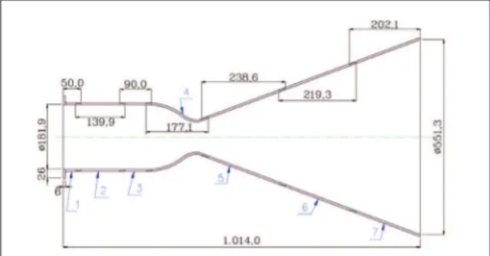
many conigurations of the referred engine. Figure 2 shows
Figure 1: Longitudinal (a), tangential (b) and radial modes (c).
Some works showed that the acoustic behavior of a combustion chamber is weakly affected by the combustion process. Comparing to room pressure and temperature conditions, the chamber cavity mode shapes remain basically the same, but its eigenfrequencies are shifted,
actually multiplied by a number deined by the ratio of
sound speed velocity at real operation temperature and at room temperature (Laudien et al., 1994).
In the development of a liquid rocket engine of 75 KN thrust by the Institute of Aeronautics and Space (IAE), the acoustic behavior of the combustion chamber is being considered. An investigation of some different combustion chambers is proposed. These studies may be done in two steps, using theoretical calculation and experimental measurements. As such, theoretical and experimental natural frequencies of the acoustic cavity are obtained, and a comparison/validation of the mathematical model can be done.
First, considering the geometry of the combustion chamber and the physical parameters of air, natural frequencies of this cavity are calculated theoretically. The acoustic frequencies can also be obtained by using a test setup to measure the sound pressure levels of this acoustic domain.
A third possible method to obtain the acoustic behavior of combustion chambers is by modeling the cavity using numerical methods such as the Finite Element Method (FEM) or the Boundary Element Method (BEM). As such, by applying virtual prototypes’ techniques, besides calculating the resonance, the associated acoustic mode shapes are obtained. With these three methods, theoretical
versus experimental comparisons can be carried out for the validation of the existing models.
Since a combustion acoustic instability (and the acoustic
mode to which it is related) is identiied, some measures can
the 75 kN LRE, which was segmented in order to assess the inner combustion chamber dynamic behavior considering
different conigurations, including the different sizes of the
nozzle. In other words, such segmentation allows verifying
the inluence of the different geometries on the acoustic
behavior of the chamber cavity, which is an important source of combustion instability. The measured acoustic parameters
of each coniguration may be compared with the respective
parameters, calculated by a mathematical model.
Table 1 describes, for each configuration, the connected segments to build up the different geometries of the combustion chamber. The numbers presented on the referred table represent the segments denoted in Fig. 2.
THEORETICAL CALCULATIONS
Equation 1 describes the considered mathematical model for the acoustic natural frequencies calculation of the
set of conigurations. The inner acoustic environment
is treated as an acoustically closed system, even though
the nozzle is in contact with the external luid or external
acoustic environment. Such approximation has showed
good theoretical versus experimental agreement (Laudien
et al., 1994).
(1)
where:
c: speed of sound;
λ: transversal eigenvalue, for m,n = 0,1,2... (Laudien et al., 1994);
k, m, n = 0,1,2... longitudinal, tangential and radial mode number directions;
Rc: combustion chamber radius;
Lc: effective acoustic length (distance between injectors faceplate and nozzle throat, less approximately one-half of the converging nozzle length).
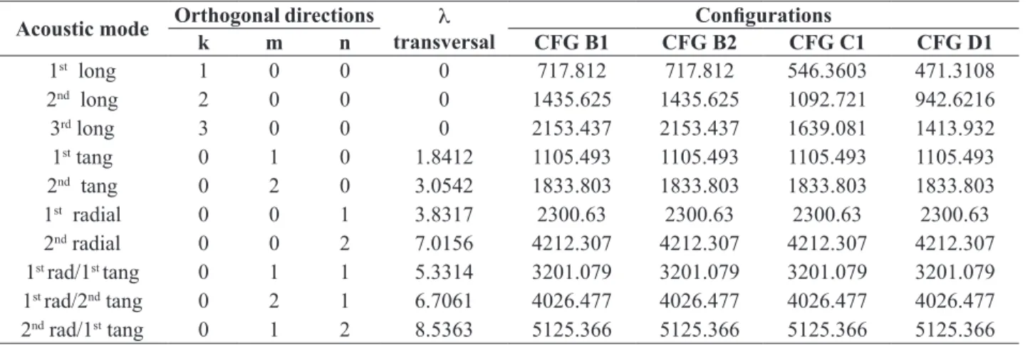
Note that in Eq. 1 the modes and its associated natural frequencies are function of the chamber geometry and the three orthogonal directions k, m and n. Table 2 gives the calculated values, assuming the temperature of the air 20ºC, universal gas constant at pressure and volume
constants ( ), which yields speed of sound
c = 343 m/s.
Figure 2: Dimensions of the segmented combustion chamber in millimeters.
Note in Fig. 2 that it is possible to built 16 conigurations
for the 75 kN LRE. Even though it is possible to assemble
such different conigurations, this paper describes the analysis performed only for the conigurations B1, B2, C1 and D1. As such, the inluences of the internal volume
and length of the combustion chamber as well as the size of the nozzle are assessed.
Figure 3 presents all the possible conigurations, with and
without nozzle, including variations of the volume of the combustion chamber and the size of the nozzle.
Figure 3: Different conigurations of the 75 kN LRE.
Table 1: Sequence of segments to be connected for each coniguration
CFG* Segments CFG* Segments CFG* Segments CFG* Segments
A1 1-4 B1 1-2-4 C1 1-2-3-4 D1 1-2-2-4
A2 1-4-5 B2 1-2-4-5 C2 1-2-3-4-5 D2 1-2-2-4-5
A3 1-4-5-6 B3 1-2-4-5-6 C3 1-2-3-4-5-6 D3 1-2-2-4-5-6
A4 1-4-5-6-7 B4 1-2-4-5-6-7 C4 1-2-3-4-5-6-7 D4 1-2-2-4-5-6-7
EXPERIMENTAL MEASUREMENTS
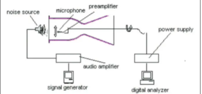
For the experimental procedure, a noise source was positioned inside the combustion chamber close to the injectors face plate. A microphone was placed in many different positions into the combustion chamber cavity. The microphone measured the acoustic pressure response due to the noise in some points.
For each microphone position, Frequency Response Functions (FRF) measurements were taken, performing azimuthal swept at each 45º, positioning the microphone in the radial direction at distances 10 mm, 40 mm and 70 mm from the structure wall, and also performing an axial swept at each 50 mm. Figure 4 shows the position points to obtain the complete set of measurement data.
propagation. For such optimization, one considered that the structural part of the combustion chamber is rigid and that the propagating acoustic waves in the inner acoustic environment of the combustion chamber assume a nearly acoustic plane wave or one-dimensional wave behavior. Such a way, the amount of measurements and data analysis
for the next conigurations can be decreased.
Acoustic plane waves are the simplest type of propagating
waves through the luid medium. The characteristic
property of such waves is that parameters such as acoustic pressure, particle displacements etc., have the same amplitude on all points of any plane, perpendicular to the direction of propagation. As an example, the propagating
waves in a conined luid, through a rigid tube, generated
by a vibrating piston, positioned at one of the edges of the tube. Any divergent type of wave, in a homogeneous medium, also assumes the characteristics of a plane wave, when it propagates at long distances from its source (Gerges, 1994). An important remark about the acoustic plane waves is that they have characteristics similar to those presented by the longitudinal waves propagating in a bar. Consequently, it is possible to deduce the wave
equation through a luid media, in which it is admitted being conined in a rigid tube, with constant transversal
section (Burnley and Culick, 1997).
As such, the survey of the conigurations B1, B2, C1 and D1 can deine the optimization procedure for the
next experiments, since some transversal measurement positions can be eliminated, assuming the plane wave behavior.
MEASUREMENT OF THE ACOUSTIC PARAMETERS
On these experimental assessments, the combustion chamber cavities were equipped with an external acoustic
Table 2: Calculated acoustic natural frequencies
Acoustic mode Orthogonal directions λ transversal
Conigurations
k m n CFG B1 CFG B2 CFG C1 CFG D1
1st long 1 0 0 0 717.812 717.812 546.3603 471.3108
2nd long 2 0 0 0 1435.625 1435.625 1092.721 942.6216
3rd long 3 0 0 0 2153.437 2153.437 1639.081 1413.932
1st tang 0 1 0 1.8412 1105.493 1105.493 1105.493 1105.493
2nd tang 0 2 0 3.0542 1833.803 1833.803 1833.803 1833.803
1st radial 0 0 1 3.8317 2300.63 2300.63 2300.63 2300.63
2nd radial 0 0 2 7.0156 4212.307 4212.307 4212.307 4212.307
1st rad/1st tang 0 1 1 5.3314 3201.079 3201.079 3201.079 3201.079
1st rad/2nd tang 0 2 1 6.7061 4026.477 4026.477 4026.477 4026.477
2nd rad/1st tang 0 1 2 8.5363 5125.366 5125.366 5125.366 5125.366
Figure 4: Microphones positioning.
Note that this measurement procedure generates a large amount of experimental data, since transversal data were measured at each 45º, positioned at 10 mm, 40 mm and 70 mm from the structure wall, taking as reference, the geometric center of the combustion chamber. Besides, axial measurements were performed at each 50 mm, up to 450 mm, depending on the chamber length.
After a irst analysis, the results indicated that an optimized
source, installed at the injection faceplate of the engine, which injected an excitation noise inside the acoustic cavity. This noise was generated by a signal generator, which provided the white noise (0 to 20 kHz) to be injected by the noise source. However, due to practical manufacturing characteristics of the referred acoustic source, the spectral content of the injected noise inside the chamber cavity was from 400 Hz to 20 kHz.
The acquired FRF, describe the acoustic response of the
luid media (acoustic cavity) due to the external acoustic
excitation. These FRF were captured by a ¼” capacitive pressure microphone, which was mounted on a thin rod, and with which it was possible to reach all the measurement positions, axial, azimuth and radial, in the chamber inner environment. This microphone was conditioned by power
supply and preampliier to measure the sound pressure level
inside the combustion chamber, when it is subjected to an external acoustic excitation. The measured acoustic pressure levels were registered by using a digital analyzer, for posterior analysis. Figure 5 shows the measurement setup.
all points of a same plane, perpendicular to the direction of the
wave propagation, may not present signiicant differences. As such, with the test results, this behavior could be veriied
and the experimental data points could be decreased, thus reducing the data to be analyzed.
RESULTS
Resonant frequencies of the combustion chamber were
identiied by analyzing the registered FRF (from 0 to 5,000
Hz), which were measured along the cavity of the chamber.
Once identiied, these frequencies were compared with
the respective values, calculated theoretically (Table 2).
As for each coniguration, the theoretical frequencies
were known, an experimental procedure of frequencies separation was performed by observing its value proximity (close to those calculated) and the higher amplitude (also considering the transversal/axial position of the
microphone). Then, for each coniguration, the acquired
FRF were analyzed and the average of the frequencies and magnitudes was evaluated, by using the transversal and axial measurements, in order to obtain the set of resonant frequencies of the referred cavity. Such a way, with the
theoretical versus experimental comparison, one can have
an idea of the inherent acoustic mode shapes in the cavity, associated with the resonance frequencies.
Nevertheless, it is important to highlight that this frequency separation method can still be improved, once the simple theoretical versus experimental frequency comparison is
not suficiently accurate, considering that the mathematical
model is a simple model of the acoustic cavity of the combustion chamber, with some approximations. As such,
a manner of conirming the calculated mode shapes is
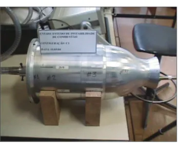
performing acoustic modal analysis of the cavity to have all the acoustic modal parameters of the cavities. This technique will be applied in further studies. Figures 6, 7, 8 and 9 show
the conigurations during test for FRF measurements.
Figure 5: Measurement set up.
It is important to mention that this technique assumes linear behavior of the acoustic cavity. As such, the inherent dynamic characteristics of the combustion chamber are independent of the excitation type and its spectral components. Therefore, the dynamic behavior of an acoustic environment is the same for different excitations.
As described on Table 2, longitudinal, radial, axial, as well as coupled modes frequencies must be measured, to obtain a complete experimental data set, which contains all the acoustic FRF, to be compared with the referred theoretical frequencies. Then, it is important to measure the required acoustic traveling waves, by positioning the microphone in the correct direction, according to the transverse or axial measurement axe. As a pressure type microphone was used, it was important to place the sensor diaphragm perpendicularly to the direction of the propagating wave.
It is expected that the propagating waves inside the combustion chamber have a plane wave behavior, as described by Gerges
are compared and an estimate of the error is described. The average magnitudes are also described.
The natural frequencies described on the referred tables were obtained by calculating averages of all measured
values, as well as the identiied resonances, visualized
on FRF.
As mentioned before, the value proximity criterion is an
inaccurate procedure. This can be conirmed, mainly in
the higher frequency bands, where the FRF present large quantity of peaks (high modal density) and the frequency
separation becomes a dificult task.
One still may consider that higher orders mathematical models are inaccurate, which present inherent acceptable errors, only for a few modes in the low frequency band. Observe the Tables 3, 4, 5 and 6 and verify that the error increases as a function of frequency. It is important to mention that the adopted measurement setup (number of points) for an acquisition up to 5,000 Hz introduces a bias error in the frequency domain of 6 Hz, approximately. This is another indication that a stochastic treatment is a method more appropriated to identify natural frequencies,
since different measurement points and signiicant bias
error may be considered.
DISCUSSION
Although the natural frequency determination procedure, using a simple mathematical model and considering the
luid room environmental conditions of temperature and
pressure, gives a reasonable indication of its dynamic characteristics, it can still be improved to yield more
accurate results. These irst studies were useful, mainly for
establishing an optimized measurement procedure, since the propagating plane wave behavior can be assumed for
such experiment. As such, for other conigurations, some
transversal measurement points can be suppressed.
Note on Table 2 that the adopted mathematical model (Equation 1) calculated the same values of radial, tangential and coupled natural frequencies for all the
conigurations of the combustion chamber. This is due
to the fact that these calculations take into account parameters as radial and transversal eigenvalues (λm,n)
and radius of the combustion chamber (Rc), which have
the same values for the referred conigurations. Then,
it means that there are no differences in the input data of the Equation 1. Therefore, the calculated axial or
longitudinal natural frequencies for the conigurations
B1, C1 e D1 present different results, since these calculations are done by considering the mode number in the longitudinal direction (k), as well as the effective length of the chamber (Lc), which is function of the
Figure 7: Coniguration C1.
Figure 8: Coniguration D1.
As the mathematical model assumes an acoustically closed
environment, the inluence of the nozzle was also veriied. Tables 3, 4, 5 and 6 describe the identiied experimental
and calculated natural acoustic frequencies. These data
Table 3: Experimental results and theoretical versus experimental comparison (B1)
Acoustic mode Experimental natural
frequency (Hz)
Theoretical natural
frequency (Hz) Error (%) Mean value (dB)
1st longitudinal 719.0 717.812 0.1 110.0
2nd longitudinal 1272.3 1435.625 12.8 95.0
3rd longitudinal 2380.6 2153.437 9.5 105.0
1st tangential 1137.5 1105.493 2.8 86.0
2nd tangential 1793.2 1833.803 2.2 85.0
1st radial 2583.6 2300.63 11.0 107.0
2nd radial 4351.6 4212.307 3.2 90.0
1st radial/1st tangential 3237.2 3201.079 1.1 98.0
1st radial/2nd tangential 4456.7 4026.477 9.6 83.0
2nd radial/1st tangential 4744.3 5125.366 8.0 93.0
Table 4: Experimental results and theoretical versus experimental comparison (B2)
Acoustic mode Experimental natural
frequency (Hz)
Theoretical natural
frequency (Hz) Error (%) Mean value (dB)
1st longitudinal 718.231 717.8123 0.01 106.40
2nd longitudinal 1311.623 1435.625 9.00 92.34
3rd longitudinal 2357.355 2153.437 8.60 105.68
1st tangential 1138.944 1105.493 2.90 88.30
2nd tangential 1875.003 1833.803 2.20 92.73
1st radial 2545.043 2300.63 9.60 101.59
2nd radial 4446.734 4212.307 5.30 98.50
1st radial/1st tangential 3267.713 3201.079 2.00 101.98
1st radial/2nd tangential 4333.683 4026.477 7.10 96.43
2nd radial/1st tangential 4515.181 5125.366 13.50 97.87
Table 5: Experimental results and theoretical versus experimental comparison (C1)
Acoustic mode Experimental natural
frequency (Hz)
Theoretical natural
frequency (Hz) Error (%) Mean value (dB)
1st longitudinal 568.5 546.3603 3.9 110.8
2nd longitudinal 1039.3 1092.721 5.2 100.0
3rd longitudinal 1452.2 1639.081 12.8 90.0
1st tangential 1050.0 1105.493 5.3 100.9
2nd tangential 2253.8 1833.803 18.6 102.2
1st radial 2461.4 2300.63 6.5 100.7
2nd radial 4331.1 4212.307 2.7 95.6
1st radial/1st tangential 2964.6 3201.079 3.1 100.2
1st radial/2nd tangential 4086.3 4026.477 1.4 91.6
2nd radial/1st tangential 4715.2 5125.366 8.7 94.9
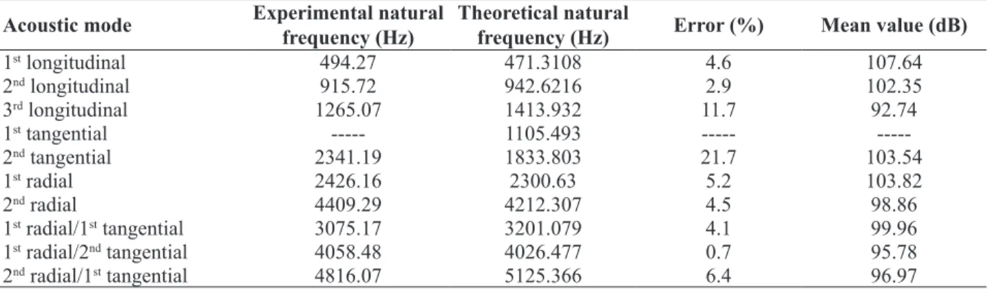
Table 6: Experimental results and theoretical versus experimental comparison (D1)
Acoustic mode Experimental natural
frequency (Hz)
Theoretical natural
frequency (Hz) Error (%) Mean value (dB)
1st longitudinal 494.27 471.3108 4.6 107.64
2nd longitudinal 915.72 942.6216 2.9 102.35
3rd longitudinal 1265.07 1413.932 11.7 92.74
1st tangential --- 1105.493 ---
---2nd tangential 2341.19 1833.803 21.7 103.54
1st radial 2426.16 2300.63 5.2 103.82
2nd radial 4409.29 4212.307 4.5 98.86
1st radial/1st tangential 3075.17 3201.079 4.1 99.96
1st radial/2nd tangential 4058.48 4026.477 0.7 95.78
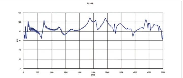
Figure 10: Axial measurement – Coniguration CFGB1.
studied geometries. It is important to consider that
conigurations B1 and B2 present the same natural
frequencies, since the considered acoustic effective
length is the same for both conigurations. Note in Fig. 1 and Fig. 2 that these conigurations are different only
by the nozzle segmentation in B2, which may have
investigated its inluence on the dynamic behavior of the
acoustic cavity.
Table 3, regarding B1, shows that the comparison of
the natural frequencies does not present signiicant
errors for the longitudinal modes. It can be noted that
the approximation of the irst longitudinal frequency,
calculated by the theoretical model, presents good correlation with the measured value (0.1% error). The second and third longitudinal eigenvalues present 12.8 and 9.5%, respectively.
Figure 10 shows a FRF, measured in axial direction, with the microphone positioned at 100 mm. Observe the curve
below and verify that the irst frequency of 719 Hz and the third of 2,380 Hz, are easily identiied, since they
present magnitudes higher than 100 dB, while the second frequency of 1,272 Hz presents a 95 dB magnitude, approximately. Comparison of the tangential frequencies, despite the low acoustic pressure levels obtained on the calculations of the averaged magnitude (around 85 dB), also presented excellent agreement between the calculated values and those measured.
Concerning the two radial frequencies, the percent errors
were 11 and 3%, respectively. These are signiicant errors,
since the mathematical approximations usually present higher errors for the higher orders’ modes, what is not the case. Still on Table 3, the coupled modes present errors of 1.1%, 9.6% and 8%, respectively.
On Table 4, corresponding to coniguration B2, it is veriied that the experimental values also present good
correlation with the values obtained by mathematical
approximation. The calculated error for the irst
longitudinal natural frequency is very small (<0.05%). The other longitudinal frequencies presented 9.0 and 8.6% error, respectively. Tangential comparisons also presented excellent correlation, with 2.9 and 2.2 %. It can
also be seen that irst, second and third coupled modes
presented 2.0%, 7.1% and 13.5% errors, respectively. For the radial frequencies, the calculated differences were 9.6 and 5.3%. Figure 11 shows the measured FRF, with microphone positioned in transversal direction, at 10 mm from the structure wall, 0º azimuth and 100 mm distance from the sound source.
For the coniguration C1, the comparisons are described
on Table 5. Considering the longitudinal frequencies,
it is veriied that the results present a good correlation for the irst and second resonances, since the calculated
errors are 3.9 and 5.2%, respectively, with the measured magnitudes of 110 and 100 dB. The resonance of the inner environment due to the third longitudinal acoustic mode presented 12.8% error, with magnitude of 90 dB. Tangential frequencies also present an excellent agreement. Note the errors of 2.8 and 2.2%, respectively, for the two tangential
natural frequencies of the coniguration C1.
Concerning the radial resonances, the errors were 11%,
at the frequency of 2,583 Hz (irst radial mode) and 3%,
for the frequency of 4,351 Hz (second radial mode). The coupled frequencies presented 10.4%, 9.6% and 8%, respectively.
Table 6 presents the comparisons concerning the
Figure 11: Transversal measurement – Coniguration CFGB2
the other conigurations, the resonances related to the longitudinal modes are easily identiied. The theoretical versus experimental comparison presents 4.6% error
for the irst longitudinal mode and 2.9 and 11.7%
for the second and third, respectively. Considering the averaged magnitudes, the measured longitudinal acoustic frequencies have 107, 102 and 92 dB. Table 6 depicts the results regarding the radial measurements.
Considering the tangential modes, it is veriied that the irst acoustic frequency (1,105 Hz), calculated by Eq. 1,
was not excited during the experimental tests. The second measured tangential frequency, when compared with the corresponding theoretical frequency, presented 21% error and its average magnitude was 103 dB. The radial modes presented 5.2 and 4.5% error, with average magnitudes of 103 and 98 dB, respectively. Finally, the coupled modes comparisons showed 4.1%, 0.7% and 6.4% errors.
Observe the FRF (Fig. 9 and Fig. 10) and note that these curves present noise below 500 Hz. This is due the low signal/noise ratio, since the generated acoustic noise (white noise) does not excite spectral components below the referred frequency, due to the manufacture characteristics of the acoustic source. As such, the measurement noises, inherent to the measurement chain, are also captured in low frequency.
Comparing Tables 3 and 4, we can verify the nozzle
inluence on the acoustic behavior of the combustion chamber cavity. Note the conigurations B1 (without
divergent) and B2 (long divergent) and verify that the
obtained values of the irst acoustic natural frequency do not change signiicantly. The second longitudinal frequency is approximately 40 Hz higher for the coniguration
B2, with long divergent. The third longitudinal mode of
the coniguration B2 is 25 Hz lower than the respective frequency of the coniguration B1, without divergent.
Other frequencies as tangential, radial and coupled can
also be compared on these tables. Therefore, signiicant
changes in the inner cavity acoustic behavior are not
veriied, when the nozzle length is increased.
CONCLUSIONS AND RECOMMENDATIONS
The procedures for evaluation of the acoustic resonances present a reasonable indication to identify these frequencies and their associated modes. Therefore, it may be considered that the mathematical model described in Eq. 1, with the inherent approximations and assumptions can be inaccurate, mainly for the higher orders modes. As such, it is important that theoretical calculations consider geometry variations for the determination of the acoustic natural frequencies of combustion chambers.
In view of better establishing the acoustic responses of the acoustic cavities, it is recommended that virtual prototypes be built up, using deterministic techniques as Finite Element Method (FEM) and Boundary Element Method (BEM), and acoustic analysis may be done to calculate the acoustic resonance frequency as well as to obtain their associated mode shapes, with more accurate models. Nevertheless, care must be taken with the limitations of these methods, since higher frequency analysis may consider a rule based on element discretization, which
may be veriied. Such rule states that an accurate model
Concerning the FRF measurements, the adopted procedure
can be optimized for other conigurations. As mentioned
in this paper, transversal measures can be performed only for a few azimuth points as well as for only one radial point, because traveling acoustic waves assume plane wave behavior in the combustion chamber.
The identiication and choice of the natural frequencies,
for consequent association to the acoustic modes, despite presenting a reasonable indication by theoretical versus
experimental comparisons, does not assure that these frequencies are the correct natural frequencies. Mainly for
the tangential, radial and coupled modes, this identiication
and choice is a hard task, since it is done by visual analysis of the measured FRF as well as the average values of the magnitudes and frequencies. It is still important to consider the modal density of the FRF, which increases
signiicantly when frequency increases, becoming the choice of the resonance peaks a dificult job.
The assessment of the inluence of the nozzle length on
the acoustic behavior of the acoustic cavity shows that
such geometry alteration does not inluence signiicantly the natural frequencies of the conigurations B1 and B2.
A procedure indicated for experimental identiication
of the eigen-values and eigen-vectors of combustion chamber is the execution of the experimental modal analysis of the referred cavities. As such, transfer functions between input/output acoustic signals, measured by two microphones, can be obtained for the determination of the acoustic modal parameters (natural frequencies and mode shapes). Experimental acoustic modal analysis and theoretical acoustic modal analysis, calculated by deterministic tools, can be compared with the theoretical model validation and determination of the dynamic parameters of the combustion chamber cavity.
As described before, some modes in transversal (tangential and radial) directions were not acoustically excited or did not have enough energy generated to excite them
satisfactorily. Such modes may be veriied by exciting the
cavity using pure tone signals. As such, all the energy of the signal is designated to excite the cavity in the required frequency.
The continuity of this combustion chamber instability survey may preview another research phase, in which acoustic noise passive insulation techniques should
be applied. Such a way, bafles, ilters and Helmholtz
resonators may designed and with these devices attenuating or eliminating the sound pressure levels inside
the chamber cavity, consequently eliminating possible combustion instabilities due to the coupling between acoustic modes and the combustion process. Once again, it is suggested that virtual prototypes may be used for design simulations and sensitivity analysis, with the different applicable apparatus.
REFERENCES
Burnley, V. S., Culick, F. E. C., 1997, “The inluence of
Combustion Noise on Acoustic Instabilities”, Air Force Research Laboratory, OMB Nº 0704-0188.
Culick, F. E. C., 2000, “Combustion Instabilities: Mating Dance of Chemical, Combustion and Combustor Dynamics, American Institute of Aeronautics & Astronautics, A00-36437 in 36th AIAA/ASME/SAE/ASEE Joint Propulsion Conference and Exhibit, Alabama, USA.
Desmet, W., Vandepite, D., 2000, “Finite Element Method in Acoustic”, Grasmech Course, Katholieke Universiteit Leuven.
Huzel, D. K., Huang, D.H., 1992, “Modern Engineering for design of liquid - propellant rocket engines”, American Institute of Aeronautics and Astronautics.
Laudien, E., Pongratz, R., Piero, R., Preclik, D., 1995, “Experimental Procedures Aiding the Design of Acoustic Cavities”, in: V. Yang, W. E. Anderson (Eds.), Liquid Rocket Engine Combustion Instability, Vol. 169, chap. 14, Progress in Astronautics and Aeronautics, AIAA, Washington, DC, pp. 377-399.
NASA, 1974, “Rocket Engine Combustion Stabilization Devices”, NASA Space Vehicle Design Criteria (Chemical Propulsion), NASA SP8113.
Gerges, S. N. Y., 2000, “Ruído, Teoria e Fundamentos”, NR Editora, ISBN 85-87550-02-0.
Santana Jr., A., et al., 2009, “Acoustic Cavities Design Procedures” Engenharia Térmica, Vol. 6, pp. 27-33.
Sutton, G. P., Biblarz, O., 2001, “Rocket Propulsion Elements”, New York, John Wiley & Sons.