Luiz Claudio M. Oliveira
[email protected]Khaled M. Ahmida
[email protected]Luiz Otávio S. Ferreira
[email protected] State University of Campinas – UNICAMP Faculty of mechanical Engineering C.P.6122 13083-970 Campinas, SP. BrazilDynamic Analysis of Silicon
Micromachined Double-Rotor
Scanning Mirror
The use of MEMS-based technologies for producing scanning mirrors enables its batch production with a consequent increase in the throughput and a decrease in the manufacturing costs per device. However, the use of Silicon as a structural material could introduce non-linearities in the device behavior due to the variation of its mechanical properties according to the crystalline orientation. The orthotropic properties when taken into account in the finite element model of the device could enhance the accuracy in the design of micromachined scanning mirrors. The model used in this paper does not take into account the orthotropic behavior, however, satisfactory results were obtained. To validate the finite element model, a modal analysis of the device was performed using the Laser Doppler Vibrometry method. The normal modes of the structure were identified and the results agree well with the finite element model. This work presents the FE model and experimental modal analysis results of a Silicon micromachined double-rotor scanning mirror.
Keywords: Microscanners, torsional oscillators, modal analysis, Laser Doppler vibrometry
Introduction
In the field of optomechatronic systems, scanning mirrors or scanners have gathered a significant attention, since they are a fundamental element of a wide variety of devices, such as barcode readers, confocal microscopes and laser printers (Wu 1997, Urbach 1982, Miyajima 2003). Scanners project laser beams that are used, for example, to produce images by raster scanning or collect images in confocal microscopy. 1
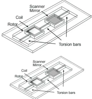
Large area devices (mm order), as the one presented in this work, have a broad spectrum of specific applications where the power of the laser beam and/or the optical aperture are a requirement for the system. In this context, the micromachined scanners competes directly with the galvanometric scanners (Rolland2004) that are fine and precise mechanical devices and whose prices are on the hundred of dollars range. Silicon mm-size micromachined scanning mirrors are an alternative to such devices. The structure usually adopted in scanners consists of a single rotor devoted to both; actuation and light beam deflection. The device presented in this work is a double-rotor scanner (Oliveira and Ferreira, 2003) where the basic idea is the separation between the actuation and the beam deflection mechanisms in order to improve the performance of each one separately, Fig. 1.
In the field of scanners some of the most important parameters are the frequency and amplitude of the torsional modes of the structure. These are the operational modes of the device and have to be enhanced in order to improve the device performance. The identification of the other modes is important due to their influence in the device operation. Such modes are responsible for the noise and must be reduced or have their frequency tuned to frequencies that do not affect the device operation in a significant way.
The presented device was prototyped using Microelectromechanical (MEMS) fabrication process. The use of such technology makes it possible the batch fabrication of such devices and causes a potential decrease in the fabrication costs due to the scale of production. On the other hand, the use of Silicon as a structural material could introduce non-linearities in the device behavior due to the variation of its mechanical properties according
Presented at XI DINAME – International Symposium on Dynamic Problems of Mechanics, February 28th - March 4th, 2005, Ouro Preto. MG. Brazil. Paper accepted: June, 2005. Technical Editors: J.R.F. Arruda and D.A. Rade.
to the crystalline orientation. The orthotropic properties should be considered for better modeling but the use of isotropic properties presented satisfactory finite element models, as discussed in the following sections.
Figure 1. Double-rotor scanner geometry. The structure consists of two square rotors linked to a fixed frame by two torsion bars, a third torsion bar connects both rotors.
The development of an analytical model that takes into account all of these aspects is not an easy task. In order to overcome these drawbacks and create a realistic model of the double-rotor scanner, a finite element model is proposed.
performed and the identified modal parameters are compared with the numerical ones.
Scanning Mirror Fabrication
The devices were made using bulk micromachining of Silicon (Kovacs 1998), thin film and mechanical assembly techniques. As substrate, a Silicon single-crystal 2" diameter, <100>, 200 µm thick, was used. A 1.30 µm SiO2 film was thermally grown and
lithographed. The micromachining process was based on the anisotropic etching of <100> Si wafer, using Potassium Hydroxide (KOH) as selective etchant (Seidel 1990, Seidel 1990b, Williams 1996). The fabrication process is described in Fig. 2.
The cooper coil was patterned separately and transferred to the silicon surface by mechanical assembly. Prototypes fabrication can be greatly enhanced by using this technique instead of conventional thin film techniques. Figure 3 shows details of the fabricated devices. Figure 3(a) presents the trapezoidal profile of the torsion bar. One of the convex corners of the rotor is shown in 3(b).
Figure 2. Scanner fabrication process: (a) Si wafer; (b) Humid Oxidation; (c) FR (Photoresist) UV exposure; (d) FR Development; (e) KOH etching.
Figure 4 shows the whole device and Table 1 its main dimensions. The packaging used was a PMMA (Poly-Methyl-Meta-Acrylate) support specially designed to accommodate the scanner.
FEA Modeling
In order to analyze the dynamic behavior of the double-rotor scanner structure a 3D finite elements analysis was conducted using the general purpose finite element package ANSYS®.
Two kinds of analyzes were performed. Initially, a modal analysis was used to identify the natural frequencies and mode shapes of the structure, where the torsional mode shapes of the scanner and their respective natural frequencies were found. Then, an harmonic analysis was conducted to determine the steady-stead response of the scanner with a load that varies sinusoidally (harmonically) with time.
The device was modeled using Solid45 finite element, see Fig.5 is element is defined by eight nodes having three degrees of freedom on each node: translations in the nodal x-, y- and z-direction. A regular pattern (mapped mesh) was generated using only hexahedrons. Table 3 presents the main simulation parameters.
(a)
(b)
Figure 3. Fabricated scanner details (a) Torsion bar; (b) Convex corner.
Figure 4. Double-rotor scanner prototype.
Table 1. Main scanner dimensions.
Scanner total size [mm2] 23 x 8.5 Mirror size [mm2] 5 x 5 Rotor size [mm2] 5 x 5 Coil lateral length [mm] 4 x 4 Torsion bars width [µm] 100 Torsion bars length [mm] 4
Table 2. Silicon properties used in the FEA model (Petersen, 1980).
Elements and mesh Element Solid45 DOFs UX, UY, UZ Element size 1.8 mm Number of elements/nodes 1290/3100
Figure 5. FEA model of the double-rotor scanner. The model includes the trapezoidal aspect of the Silicon device.
Table 3 Silicon properties used in the FEA model (Petersen, 1980).
Bulk Silicon Properties Density 2330 Kg/m3 Young modulus 45 GPa Poisson ratio 0.09
The FEA modal analysis shows the first five modes of the double-rotor scanner structure. From these results we can identify the torsional modes of the structure, in this case the 3rd and the 5th.
These modes are the main modes of the device and can be easily identified experimentally.
(a) (b)
(c) (d)
(e)
Figure 6. FEA predict modes: (a) 1st
mode - 677 Hz; (b) 2nd
mode - 1130 Hz; (c) 3rd mode (torsional) - 1595 Hz; (d) 4th mode – 2528 Hz; (e) 5th mode (torsional) – 2766 Hz.
Experimental Characterization
In order to validate the FEA results two experiments were response of the device. In this way the frequency and amplitude of the main torsional modes could be obtained. Then, a laser Doppler vibrometry was done to perform a modal identification. These experiments are explained in the following sections.
Frequency Response
Figure 7 presents a schematic view of the measurement setup used in the device characterization. A laser beam is reflected by the mirror and directed to a semiconductor position sensitive device, PSD, which generates an electric signal proportional to the deflection angle of the laser beam. This output signal is read by the acquisition system that generates the scanner response.
The acquisition system is composed basically by a function generator and by a digital oscilloscope. An user interface was specifically developed to control the instrumentation and to automatize the measurements. The interface changes linearly the frequency of the AC magnetic field generated by the magnetic circuit and reads the electric output signal generated by the PSD. The results of the measurements were archived in data file for posterior analysis.
Figure 7. Schematic view of the characterization setup.
Figure 8 shows the frequency response for the double-rotor scanner. As expected for this second-order system two resonant peaks were detected.
A typical second-order system response with resonant frequencies of 1316 Hz and 2542 Hz was obtained. The double-rotor scanner show a maximum optical deflection angle of 8o pp at the first resonant peak, 1316 Hz. Quality factors, Q, of 200 and 422, were achieved what implies in a bandwidth of 6.6 Hz and 6.0 Hz, for the first and second resonant peaks respectively. Such performance in accordance with the performance of commercial devices and with previously published results for single-rotor devices (Barbaroto 2002).
Laser Doppler Vibrometry
The numerical results obtained via the finite element analysis were validated experimentally. An excitation chirp signal, in the range of 1 Hz to 4 kHz with 0.5Hz resolution, was sent to the rotor and was used as the reference signal. The out-of-plane velocity of the scanner surface was measured with a laser Doppler vibrometer (Polytec OFV 330) aiming the laser beam orthogonal to its surface. The excitation and the response signals were acquired using the HP-VXI data acquisition system and LMS CADA-X® software package, Fig. 10. The Measurements were taken at 23locations on the surface of the double-rotor scanner, as shown in Fig. 9.
Figure 9. LDV setup. (1) Power amplifier, (2) LDV module, (3) electromagnetic actuator, (4) Laser, (5) Double-rotor scanner.
Figure 10. LDV measurement points.
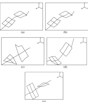
The experimental modal analysis resulted in the following mode shapes and natural frequencies. The first five mode shapes of the scanner were identified using the measured FRFs and the LMS® modal analysis package. These mode shapes are shown in Fig. 11, with a special attention to the 2nd and the 5th mode shapes of
torsional characteristic. A good agreement was found between the numerically predicted and the experimentally identified modal parameters, with a small difference.
(a) (b)
(c) (d)
(e)
Figure 11. The experimentally identified mode shapes of the scanner: (a) 1st mode – 658 Hz; (b) 2nd mode – 1357 Hz; (c) 3rd mode (torsional)– 1258 Hz; (d) 4th
mode – 2269 Hz; (e) 5th
mode (torsional) – 2518 Hz.
Comparative Analysis
Figure 12 presents the FEA predicted modes and the experimental torsional modes of the device, the most important modes in this kind of device. According to this figure the measured mode shapes are in good agreement with the FEA predicted ones. Observe that the experimentally identified mode shapes could be related to the fact of using a macro-sized LDV with a relative big beam spot, when compared to the scanner dimensions. Better experimental analysis could be conducted by using a specific micro LDV, suitable for MEMS.
(a) (b)
(c) (d)
Figure 12. FEA predicted and experimental torsional modes of the device: (a) 1st
FEA torsional mode -1595 Hz; (b) 1st
experimental torsional mode - 1248 Hz; (c) 2nd FEA torsional mode - 2765 Hz; (d) 2nd experimental torsional mode - 2518 Hz.
modes and their frequencies are in good agreement with the experimental results obtained.
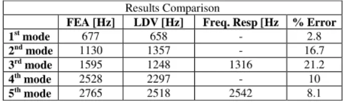
Table 4 Results comparison between the FEA, LDV and Frequency Response methods.
Results Comparison
FEA [Hz] LDV [Hz] Freq. Resp [Hz % Error
1st mode 677 658 - 2.8
2nd mode 1130 1357 - 16.7
3rd mode 1595 1248 1316 21.2
4th mode 2528 2297 - 10
5th mode 2765 2518 2542 8.1
Conclusions
Numerical models are considered as important tools in design processes. Finite Element Analysis (FEA) is one of the most reliable tools for building such models. The FEA model of the double-rotor scanner was build and tested. A double-rotor scanning mirror was fabricated using Silicon. This scanner has shown a sufficient deflection angle but this angle can still be improved by optimizing the geometry of the scanner mirror or by improving the coupling between the magnetic circuit and the scanner coil. In order to validate the numerical model, an experimental modal analysis was performed on this scanner using laser Doppler vibometry (LDV). The numerically-predicted dynamical behavior of the scanner was in good agreement with the experimentally-measured frequency response. The torsional modes, which are the most important modes in such kind of device, were correctly predicted with an acceptable margin of discrepancy of less than 15%. The accuracy of the numerical model can still be improved by taking into account the orthotropic characteristics of the Silicon and the acoustic effects of the surrounding air on the scanner structure. The use of finite element based methods in device modeling has shown to play an important role in enhancing the accuracy of micromachined scanning mirrors in the design process.
Acknowledgment
This work was partially supported by FAPESP and CNPq (MCT). The authors wish to thank them for the support.
References
Barbaroto, P. R., Ferreira, L. O. S., and Doi, I., 2002, “Micromachinedscanner actuated by electromagnetic induction.”, Proceedings of SPIE”, Vol. 4092, pp. 691–698
Kovacs, G. T. A., Maluf, N. I., and Petersen, K. E., 1998, “Bulk micromachining of silicon.”, Proceedings of IEEE, Vol. 86, No. 8 pp. 1536– 1551.
Miyajima, H., Asaoka, N., Isokawa, T., Ogata, M., Aoki, Y., Imai, M., Fujimori, O., Katashiro, M., and Matsumoto, K., 2003, “A MEMS electromagnetic optical scanner for a commercial confocal laser scanning microscope.”, Journal of Microelectromechanical Systems, Vol. 12, No. 3 pp. 243–251.
Oliveira, L. C. M. and Ferreira, L. O. S., 2003, “Silicon Micromachined Double-Rotor Scanner.”, Proceedings of SPIE, Vol. 21, No. 3, pp. 634–642.
Oliveira, L. C. M., 2006, “Contributions for the Improvement in the Performance and Manufacture Viability of Planar Inductive Scanners” (In Portuguese), Ph.D. Thesis, State University of Campinas, Campinas, S.P., Brazil, 206 p.
Oliveira, L. C. M., Barbaroto, P. R., Ferreira, L. O. S. and Doi, I., 2006, “A novel Si micromachined moving-coil induction actuated mm-sized resonant scanner”, J. Micromech. Microeng., Vol. 16, pp.165-172,
Petersen, K. E. ,1980, “Silicon torsional scanning mirror.”, IBM J. Res. Develop., Vol. 24, No. 5, pp. 631–637.
Seidel, H., Csepregi, I., Heuberger, A., and Baumgartel, H. ,1990, “Anisotropic Etching of Crystalline Silicon in Alkaline Solutions.”, J.
Eletrochem. Soc., Vol. 137, No. 11, pp. 3612–3626.
Seidel, H., Csepregi, I., Heuberger, A., and Baumgartel, H. ,1990b, “Anisotropic Etching of Crystalline Silicon in Alkaline Solutions. II - Influence of Dopants.”, J. Eletrochem. Soc., Vol. 137, No. 11, pp. 3626– 3632.
Urbach, J. C., Fisli, T. S., and Starkweather, G. K. ,1982, “Laser scanning for electronic printing.”, Proceedings of IEEE, Vol. 70, pp. 597– 618.
Williams, K. R. and Muller, R. S. ,1996, “Etch Rates for Micromachining Processing.”, Journal of Microelectromechanical Systems, Vol. 5, No. 4 pp,. 256–269.
Wu, M. C. ,1997, “Micromachining for optical and optoelectronic systems.”, Proceedings of IEEE, Vol. 85, No. 11, pp.1833–1856.