Abstract—Plunge shaving is the most advanced gear finishing technique which only needs radial infeed. Its advantages include increased productivity, accuracy, long tool life, and a simple machine structure. For the plunge shaving method, the gear tooth modification only depends on the surface geometry of the plunge shaving cutter. The analytical description of the gear with tooth modifications is firstly constructed by B-spline surface fitting. Then, the grinding wheel profile is parameterized and optimized for minimizing the surface deviations of theoretical and ground (from re-sharpening machine) tooth surfaces of the plunge shaving cutter, in which the topographic error has been reduced. The cutting trace of plunge shaving cutter has also been analyzed so that the shaving efficiency can be improved.
Index Terms—Gear plunge shaving, Cone grinding wheel, Topographic error, Shaving cutter serration.
I. INTRODUCTION
Gears are the most important components in transmission systems. Modifications of gear teeth can accommodate errors and deformations encountered in the manufacture, assembly, and operation of gear pairs. Litvin [1] provided a double crowned gear modified both in lead and in profile with improved transmission error. Wagaj and Kahraman [2] investigated the durability of helical gear affected by tooth modifications. Kahraman et al. [3] presented a gear wear model analyzing the influences of tooth modification.
Gear shaving is one of the most efficient and economical processes for gear finishing after hobbing or shaping. Among the four basic shaving methods, plunge shaving is the most advanced gear finishing technique which only needs radial infeed. Its advantages include increased productivity, accuracy, long tool life, and a simple machine structure [4]. The basic meshing condition of 3D crossed-axis helical gear pair was first derived by Litvin [5], and it has been widely adopted as the fundamental assumption for simulation of gear shaving.
In recent years, how to induce gear tooth modification by shaving has become an important subject of research. Chang et al. and Hung et al. [6]-[8] derived the mathematical model of traditional shaving machine and investigated the influences of parameters on tooth lead modifications. Litvin
Shinn-Liang Chang, corresponding author, Institute of Mechanical and Electro-mechanical Engineering, National Formosa University, Huwei Township, Yunlin County 632, Taiwan, ROC (email: [email protected]), Phone: 886-5-6315429, Fax: 886-5-6312110.
Jia-Hung Liu, Mechanical Engineering Department, National Chiao Tung University, Hsinchu 30010, Taiwan, ROC (email: [email protected])
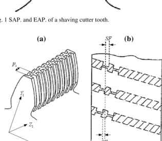
et al. [9] proposed a method for shaving gears with double crowning by CNC shaving machine. For shaving methods other than plunge shaving, the gear tooth modification is accomplished by tooth modifications of the shaving cutter and the coordinated motions between cutter and gear. For the plunge shaving method, however, it only depends on the surface geometry of the plunge shaving cutter. Focusing on the surface geometry of shaving cutter, what’s really significant is precision of the region between SAP. (start of active profile) and EAP. (end of active profile) as shown in Fig. 1. In gear shaving, SAP. of cutter tooth shaves the gear tooth tip while EAP. shaves the gear tooth root. Traditionally, the cutter surface geometry results from a cutter re-sharpening machine by trial and error, which is very time-consuming.
Fig. 1 SAP. and EAP. of a shaving cutter tooth.
Fig. 2. Design parameters of plunge shaving cutter serration (a) serration pitch (b) serration displacement.
Moreover, the shaving cutter tooth surfaces have serrations extending from the top land to the root fillet of the teeth whose sharp edges exert a cutting action on the work
Research on Gear Plunge Shaving for Gears with
Tooth Modifications
Jia-Hung Liu Shinn-Liang Chang
gear due to the relatively lengthwise sliding motion. Serrations are an important feature for all shaving cutters, but for plunge cutters their importance is vital. The serrations related to such type of cutter must have a helical pattern, as shown in Fig. 2, and they have to be manufactured with a very high precision CNC slotting machine in order to obtain the best results. Thus, the surface roughness of the work gear after shaving is affected primarily by the arrangement of these serrations. In this paper, the analytical description of the gear with tooth modifications is first constructed by B-spline surface fitting. Then, the grinding wheel profile is parameterized and optimized for minimizing the surface deviations of theoretical and ground (from re-sharpening machine) tooth surfaces of the plunge shaving cutter. Efficiency is greatly improved by avoiding the traditional trial and error method. Then, based on the optimized cutter surface, a method for optimizing the serration displacement is proposed to improve the cutting efficiency.
II. SURFACE INTERPOLATION OF THE MODIFIED GEAR TOOTH SURFACE
To integrate the modified gear tooth surfaces into the analytical process, especially for those with both lead and profile modifications, B-spline surface interpolation is selected for its ease of manipulation. In practice, the sampling points of the modified surface can be obtained by CMM (Coordinate Measuring Machine) or from other sources. In this paper, for studying purposes, the most commonly used numerical model is adopted for generation of interpolating points: the tooth flank is modified in profile (root to tip) and lead (side to side) directions independently as shown in Fig. 3 [2]. The magnitude at the tip at and the gear roll angle at the start αt define the boundaries of the tip relief. Between these
two points, the profile follows a linear trajectory. Similarly, the magnitude ar and the starting roll angle αr define the
starting point of a root modification. The amount of lead crowning is denoted by h.
Fig. 3. Model of gear tooth modifications [2].
A B-spline representation enables the simulation of surface irregularities and the control of small tooth geometric
modifications, such as rounding and reliving. Given a grid of sampling points Dk,A ( 0≤ ≤k m and 0≤ ≤A n) and orders
p and q (degrees p−1 and q−1), it can be represented as below [10]:
, , , ,
0 0
( ) ( )P
m n
k i p k j q i j i j
D N s N t
= =
=
∑∑
A A (1)
, where sk ’s and tl ’s are the chosen parameter
values;Ni p, ( )sk (Nj q, ( )tA ) is the i-th (j-th) B-spline basis
function of order p ( q ); and Pi j, ’s ( 0≤ ≤i m and 0≤ ≤j n) are the control points. Once the numbers of sampling points m and n are selected, then the B-spline orders
p and q are limited by (2):
3 1 3 1
,
1 1
m n
p q
m n
+ +
≥ ≥
+ + (2)
, that is, p≥3 and q≥3.
Solving (1), Pi j, ’s can be obtained, and the interpolated B-spline surface 2
I
∑ can be represented as follows:
2 , , ,
0 0
( , ) ( ) ( )P
m n I
i p j q i j i j
u v N u N v
= =
∑ =
∑∑
(3), where u and v denote the surface parameters; 2 denotes the surface of gear tooth; and I denotes the surface obtained by interpolation.
TABLE 1BASIC DATA OF THE TARGET GEAR TOOTH SURFACE. Gear data
Normal module
m
n 1.5 Diameter of base circle db2 119.618mm Diameter of addendum circle dadd2 126.71mmDiameter of root circle dr2 119.33mm Diameter of pitch circle dp2 123.915mm
Normal pressure angle in pitch circle αpn2 14.5° Face width fw2 18mm
Gear tooth number Z2 79 Helix angle in pitch circle βp2 17° Normal circular tooth thickness spn2 2.32mm
TABLE 2DATA OF GEAR TOOTH MODIFICATIONS OF THE TARGET SURFACES.
Parameter at at at at at
2
I
∑ 6e-3mm 31.8° 6e-3mm 28.2° 6e-3mm
Fig. 4. Validations of the interpolated gear tooth surface.
III. OPTIMIZATION OF TOPOGRAPHIC ERRORS OF GEAR PLUNGE SHAVING CUTTER
The tooth surface of the shaving cutter is usually finished last using a cone grinding wheel on the shaving cutter re-sharpening machine. Because the topographic accuracy of the plunge shaving cutter maps directly onto the work gear, it is important to identify the topographic error of the ground tooth surfaces ∑1G in comparison to the theoretical
1T
∑ where 1 denotes the surface of shaving cutter tooth; G
and T denote the surfaces derived from the re-sharpening machine and the interpolated surfaces, respectively.
The basic meshing condition for the crossed helical gear set [5] is used to calculate the basic geometric data for the shaving cutter. It needs the following eight basic items: the tooth number Z1, the normal circular tooth thickness spn1, the helix angle βp1 of the shaving cutter; the tooth number
2
Z , the normal circular tooth thickness spn2, the helix angle
2
p
β of the work gear, and the normal module mpn and pressure angle αpn, of the shaving cutter and work gear. Fig. 5 [11] shows the coordinate system of the CNC shaving machine. Considering coordinate transformation
1 1 1 1 12 2 2 2 2
1 1 1 1 12 2 2 2 2
[ 1] ( ) ( , )
[ ] ( ) ( , )
T
T
x y z
x y z R Z
n n n R Z
φ φ
= =
= =
r M r
n L n
(4) and meshing equation
2 2 2
( , , ) h
f R Z φ =n ‧vh(12) =0 (5)
simultaneously, the theoretical tooth surface of shaving cutter
1T
∑ can be derived from surface 2
I
∑ . M12 and L12 are matrices for transforming position and unit normal vectors (r2 and n2) of surface
∑
1T from coordinate system S2 (gear)to S1 (shaving cutter), and v(12)h denotes the vector of
relative velocity on auxiliary coordinate system Sh..
Likewise, as shown in Fig. 6 [11], the ground surfaces of shaving cutters
∑
1G can be obtained by coordinate transformations from Sg (grinding wheel) to Ss (shavingcutter)
[ 1]
[ ]
T
s s s s sg g
T
s xs ys zs sg g
x y z
n n n
= =
= =
r M r
n L n
(6) and the meshing equation
( g, g, ) m
g u θ φ =n ‧vm(sg) =0 (7)
Fig. 5. Coordinate systems of gear shaving machine [11].
Fig. 6. Coordinate systems of shaving cutter re-sharpening machine [11].
For interpolated gear tooth surfaces
∑
2I , the corresponding data of plunge shaving cutter and grinding wheel are presented in Table 3. Obtaining theoretical tooth surface∑
1T as well as ground tooth surfaces∑
1G through (4)-(7), the topographic errors are calculated by, ,
1 1
, ,
, ,
(tan ( ) tan ( ))
T G
i j i j Topo
i j i j T G i j i j
y y
e r
x x
− −
= − , i=1,2,…,5, j=1,2,…,9 (9)
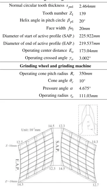
Z cross-sections, in which theoretical surfaces are presented in straight solid lines, while the corresponding ground ones are shown in dashed lines. From S.A.P to E.A.P. of the cutter tooth, errors are obvious that the grinding wheel needs to be dressed. Traditionally, it is modified back and forth for the desired accuracy, which is very time-consuming. In this section, optimization is performed by adjusting the cone angle of the grinding wheel θc and the profile of the grinding wheel.
TABLE 3DATA OF CUTTER AND GRINDING WHEEL.
Fig. 7. Topographic errors between theoretical and ground shaving cutter tooth surfaces.
The grinding wheel is further parameterized as shown in Fig. 8. Coordinate system Sg′ is attached to the unmodified profile. Within the effective length LA+LB (LA=4.2mm, LB=5.5mm), the profile with four sections are defined by wA,
A
h , wB and hB. Represented in Sg′, the four points A2, A1, B1 and B2 are fitted by a B-spline curve with order 4.
Fig. 8. Parameterized profile of grinding wheel for optimization.
TABLE 4RESULTS OF OPTIMIZED PROFILE PARAMETERS.
Initial design (mm) Optimum design (mm)
wA 0.1 0.561
hA 0 0.056
wB 0.1 0.538
hB 0 0.235
Fig. 9. Topographic errors between theoretical and ground shaving cutter tooth surfaces after optimization.
To improve the topographic errors between ∑1T and ∑1G, the problem formulation is formulated:
find x=[ ,θc w h w hA, A, B, B] that minimizes
5 9 , 1 1
( )
Topo i j i j
e
= =
∑∑
xsubject to , 103
Topo i j
e < − mm, i=1,2,…,5, j=1,2,…,9, and 0.5° ≤θc ≤30°
4 4
10 wA LA 10
− < < − −
; 0<hA<3 ;
4 4
10 wB LB 10
− < < − −
; 0<hB<3 (unit: mm)
The optimized profile parameters are presented in Table 4, and the cone angle converges to θc =2.382D. The profile of the grinding wheel is considered straight sided initially. When it reaches the optimum, the profile is modified for Plunge shaving cutter
Normal circular tooth thickness spn1 2.464mm Tooth number Z1 139 Helix angle in pitch circle βp1 20° Face width fw1 20mm
Diameter of start of active profile (SAP.) 225.922mm
Diameter of end of active profile (EAP.) 219.537mm
Operating center distance Eo 173.04mm
Operating crossed angle γo 3.002° Grinding wheel and grinding machine
Operating cone pitch radius Rc 350mm
conjugation to the shaving cutter. The topographic errors between
∑
1T and∑
1G are shown in Fig. 9, where the errors are all controlled below 10-3mm.IV. DESIGN OPTIMIZATION OF THE GEAR PLUNGE SHAVING CUTTER SERRATIONS
Plunge shaving is characterized by a radial feed stroke without transverse feed. The serrations in consecutive shaving cutter teeth must be shifted longitudinally so that the cutting marks on the work gear move in a lengthwise direction, which can even the cutting residue and improve the surface roughness. As shown in Fig. 2, the design parameters for the serrations of the plunge shaving cutter are the serration pitch ps and the serration shift SF between
consecutive cutter teeth.
The trace of the plunge shaving cutter’s cutting edge on the work gear during the cutting process is illustrated schematically in Fig. 10 [11]. At the beginning of a shaving cycle, the cutting edge presses into the work gear surface, moves on its tooth surface due to the relative motion, and then removes chips when contact stress reaches local ultimate stress. Therefore, the front cutting edge produces the desired cutting action.
Fig. 10. Cutting path of the cutting edge on the work gear [11]
Besides, the cutting efficiency can be characterized by the “cutting-down ratio” rcd , which is the ratio between the
height of the second peak and that of the first peak, shown in Fig. 11. Smaller rcd represents better cutting efficiency because most of the material can be removed in the first few cutting cycles.
According to the data of gear, shaving cutter and the grinding wheel listed in Tables 1 to 4, after optimizing the cutter tooth surface, the serrations can also be optimized to improve the cutting efficiency. The problem formulated as below:
find serration shift SF
that minimizes cutting-down ration rcd subject to SF×N1≥ ps
The value of SF goes from 0.243 mm to 0.376 mm. For the plunge shaving cutter with tooth number N1=137 and serration pitch ps =1.7mm, the cutting-down ratio has been improved form 0.318 to 0.242 (first peak=3.1μm, second peak=
0.7
μ
m
).Fig. 11. Cutting residue (a) first cut (b) first peak (c) second peak.
V. CONCLUSION
For gear plunge shaving, the analytical descriptions of crowned gear and hence plunge shaving cutter have been constructed so that the grinding wheel can be optimized to minimized the topographic error. The cutting trace of plunge shaving cutter has also been analyzed so that the final real tooth forms can be predicted. The proposed mathematical model of design optimization can be use to calculate the optimum of grinding wheel profile and cutter serration, which can facilitate the design and manufacture of gear shaving cutter.
ACKNOWLEDGMENT
The authors would like to acknowledge the support of Taiwan National Science Council through grant No. NSC97-2221-E-150-013.
REFERENCES
[1] Litvin, F.L., (2001) Helical and spur gear drive with double-crowned pinion tooth surfaces and conjugated gear tooth surfaces. United States Patent, Patent No: US6205879.
(a)
(b)
(c)
First cut
First peak
[2] Wagaj, P., Kahraman, A. (2002) Influence of tooth profile modification on helical gear durability. Journal of Mechanical Design 124: 501-510. [3] Kahraman, A., Bajpai, P., Anderson, N. E. (2005) Influence of tooth
profile deviations on helical gear wear. Journal of Mechanical Design 127: 656-663.
[4] Bianco, G. (2000) Gear Shaving. Jiuge, Beijing.
[5] Litvin, F. L. (1994) Gear Geometry and Applied Theory. PTR Prentice Hall, New Jersey.
[6] Chang, S. L., Lin, H. J., Chu, C. H., Liu, J. H., Hung, C. H. (2007) Simulation of gear shaving machine and tooth contact analysis of the shaved gears. The 2007 IAENG International Conference on Industrial Engineering, Hong Kong.
[7] Chang, S. L., Liu, J. H., Jin, K. W., Hung, C. H. and Chen, S. H. (2008). Robust design for gear transmission error. The 2008 IAENG International Conference on Industrial Engineering, Hong Kong. [8] Hung, C. H., Liu, J. H., Chang, S. L., Lin, H. J. (2007) Simulation of
gear shaving with considerations of cutter assembly errors and machine setting parameters. The International Journal of Advanced Manufacturing Technology 35(3-4): 400-407.
[9] Litvin, F. L., Fan, Q., Vecchiato, D., Demenego, A., Handschuh, R. F., Sep, T. M. (2001) Computerized generation and simulation of meshing of modified spur and helical gears manufactured by shaving. Computer Methods in Applied Mechanics and Engineering 190: 5037-5055. [10] Piegl, Les, Tiller, Wayne (1997) The NURBS Book, 2nd edition.
Springer-Verlog, Berlin.
[11] Hsu, R.H. (2006) Theoretical and practical investigations on the design of plunge shaving cutter. Ph.D. Dissertation, National Chung Cheng University.
Revised version 1
Date of Modification: 2009/9/19 Description of the changes:
1. Reference No. 11 is added to the reference list. 2. Reference No. 11 is added to the figure descriptions
![Fig. 3. Model of gear tooth modifications [2].](https://thumb-eu.123doks.com/thumbv2/123dok_br/17095205.237011/2.892.450.828.591.855/fig-model-gear-tooth-modifications.webp)
![Fig. 5. Coordinate systems of gear shaving machine [11].](https://thumb-eu.123doks.com/thumbv2/123dok_br/17095205.237011/3.892.454.812.91.628/fig-coordinate-systems-gear-shaving-machine.webp)
![Fig. 10. Cutting path of the cutting edge on the work gear [11]](https://thumb-eu.123doks.com/thumbv2/123dok_br/17095205.237011/5.892.494.789.85.679/fig-cutting-path-cutting-edge-work-gear.webp)
