Vol. 11, No. 1, February 2014, 159-173
Reduction of Torque Ripple in DTC Induction
Motor Drive with Discrete Voltage Vectors
Marko Rosi
ć
1, Borislav Jefteni
ć
2, Milan Bebi
ć
2Abstract: This paper presents а practical implementation of direct torque control (DTC) of an induction machine on MSK2812 DSP platform, and the analysis of possibilities for reduction of torque ripple. Basic theoretical background relating the DTC was primarily set and the obtained experimental results have been given. It is shown that the torque ripple can be reduced by adjusting the intensity of voltage vectors and by modification of hysteresis comparator, while the simplicity of the basic DTC algorithm has been maintained.
Keywords: Induction motor drive, Direct torque control, Torque ripple, Hysteresis comparator modification, DSP.
1 Introduction
Direct Torque Control (DTC) is the youngest control technique of AC machines, and has been present for more than two decades [1]. Due to its preferable characteristics, such as quick torque response and simplicity of practical implementation, DTC is considered to be an alternative to the Field Oriented Control (FOC) techniques [2]. DTC algorithm with discrete voltage vectors (classical DTC) presents the simplest form of flux and torque control without rotating coordinate transformation and complicated mathematical calculations. However, the main drawbacks of this algorithm are high torque and current ripple and variable switching frequency [3]. These imperfections have been overcome with more or less complicated algorithms using pulse width modulation (PWM) or space vector modulation (SVM) and PI regulators [4-5]. Thus, the torque ripple has been significantly reduced, to the detriment of bandwidth degradation due to PI regulators and usage of more complex calculation.
This paper shows the analysis of torque and current ripple reduction using DTC with discrete voltage vectors involving modification of hysteresis comparators to obtain adjustable voltage vector intensity. The primary idea is to retain the simplicity of the classical DTC algorithm without PI regulators and coordinate transformations, and to reduce torque ripple and provide constant switching frequency.
1Faculty of Technical Sciences Čačak, Svetog Save 65, 32000 Čačak, Serbia, E-mail: [email protected] 2School of Electrical Engineering, Bulevar kralja Aleksandra 73, 11120 Belgrade, Serbia
E-mails: [email protected]; [email protected]
2
Theoretical Review of DTC with Discrete Voltage Vectors
The direct torque control of the induction machine with voltage source inverter (VSI) can be achieved by controlling of machine stator flux with optimal switching state selection. Electromagnetic torque of the induction machine depends on the mutual position of stator and rotor flux and can be presented by the following equation:
e 2
3
sin(θ θ )
2 s r
m
s r
s r m
L P
L L L
m = ⋅ −
− ψ ψ , (1)
where P isthe number of pole pairs, Ls, Lr are the stator and rotor inductances, Lm is the mutual inductance; ψs , ψr are the stator and rotor flux magnitudes,
and θ ,θ
s r are the stator and rotor flux angles with respect to reference axis.
Rotor time constant Trgrows with machine power (Tr= 0.12 s, for 2.2 kW induction motor). That explains slow change of rotor flux which can be neglected during the timeΔt. In that way, quick change of stator flux in respect to rotor flux enables direct torque control. Stator voltage equation in stationary reference frame is given by (2):
s s s s
d d
R
t
= +
u i ψ , (2)
s s t
Δψ =uΔ , (3)
where us,is and
s
ψ are stator voltage, current and flux vectors respectively, and
Rs is stator resistance.
Neglecting the stator resistance Rs, variation of the stator flux Δψs in (2)
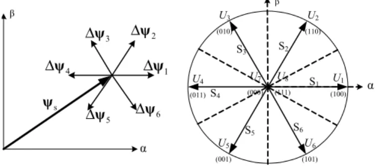
can be presented by (3). By selecting one of the eight voltage vectors of the three phase inverter (Fig. 1), it is possible to influence the position of stator flux in respect to the slowly changing rotor flux. The variation of rotor flux magnitude and phase angle can be neglected during the timeΔt. This simplification is reasonable since the sampling time (Ts = Δt), on real-time DSP based systems, is much less than rotor time constant Tr In this way, the increase or decrease of stator flux intensity or angle, and thus the torque, can be provided by selecting an optimum voltage vector. Increment of the stator flux during the time Δt is illustrated in Fig. 1.
s ψ 1 Δψ 2 Δψ 3 Δψ 4 Δψ 5
Δψ Δψ6
U1 (100) S1 S2 S3 S4
S5 S6
U2 (110) U3 (010) U4 (011) U5 (001) U6 (101) U7 (000) U8 (111) α α β β
Fig. 1 – Voltage vector impact to the stator flux amplitude and angle variation. Table 1
Voltage vector selection.
Sm
S
1 0 –1
1 Uk+1 U7 or U8 Uk–1
–1 Uk+2 U7 or U8 Uk–2
Demands for flux S and torque Sm are obtained from hysteresis comparators which are presented in Fig. 2. Depending on the value of estimated stator flux and torque, demands for increasing S = 1, decreasing S = –1 or null demand S = 0 are generated. Demand S = 0 occurs when error Δm lies within torque hysteresis limits.
ref s
Δ =ψ ψ −ψ
Sψ S
m
ref
m m m
Δ = −
Fig. 2 – Flux hysteresis comparator (left) and torque hysteresis comparator (right).
The accuracy of estimated stator flux directly affects the accuracy of the electromagnetic torque estimation by (4):
α β β α
3
( )
2
e s s s s
m = P i − i , (4)
where αs, βs are stator fluxes in stationary αβ reference frame, and iαs, iβs
For this reason, accurate estimation of stator flux position is the matter of great importance. Various stator flux estimation methods are subjects of many scientific papers. Great research effort has been made in the realization of flux estimator which will be reliable over a wide speed range. For instance, flux estimators which relies on the machine voltage model has poor characteristics at low speed, due to integration signal contaminated with DC offset. Estimator based on current machine model has satisfactorily results at low speed but poor results at high speed. Method based on a combination of voltage and current model is proved to be reliable method of flux estimation [6]. This estimator provides good accuracy and robustness of estimated flux even with non-ideal machine parameters. Further, it permits flux estimation at all (including zero) speeds and exhibit speed-invariant dynamics which is important for wide speed range drives [7].
Here, the flux estimation is realized with current model estimator by following estimations (5):
2 2 d , , d d , , d
s r m m r r m r
s s r s r r r
r r r r
r
s r m m r m r
s s r s r r r
r r r r
L L L L R L R
i i
L L t L L
L L L L R L R
i i
L L t L L
α
α α α α α β
β
β β β β β α
− ψ
ψ = + ψ = − ψ − ω ψ
ψ −
ψ = + ψ = − ψ + ω ψ
(5)
where Rr is rotor resistance and r is rotor speed.
The reason for this is simplicity of digital implementation and the fact that the application will be tested at low speeds at which current model estimator has good results.
3 Algorithm
Implementation on DSP Platform MSK2812
Direct torque control algorithm with discrete voltage vectors was implemented on Technosoft platform MSK2812 [8]. Setup MSK2812 consists of the power module ACPM750 (750W/230V) with rectifier, three phase IGBT inverter bridge and 32-bit digital signal processor TMS320F2812 with fixed point arithmetic. DSP F2812 runs at 150MHz (6.67ns). All quantities used in calculation are represented in Q16 format where 16 bits represent fractional part of a number, 15 bits integer part and 1 bit goes to the number sign.
Induction motor is equipped with two phase incremental encoder with 500 pulses per revolution. Motor parameters for star connection are given in the Table 2.
on every 10th interrupt which is 0.5 ms. This loop is responsible for speed measurement, setting of the references for flux and torque, and data collection.
Table 2
SIEBER LS71 motor parameters.
Un [V] 400 Rs [Ω] 24,6
In [A] 0,95 Rr [Ω] 16,1
Pn [W] 370 Lm [H] 1,46
nn [min-1] 2860 Ls [H] 1,48
p [pole num.] 2 Lr [H] 1,48
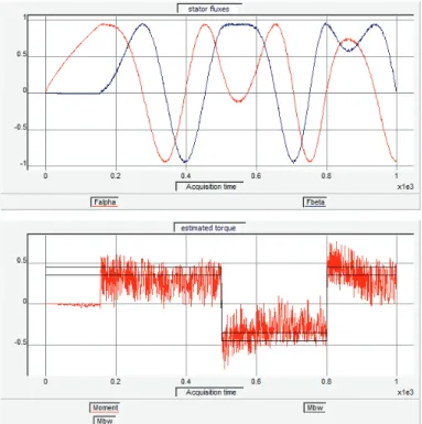
Hysteresis comparators width are set to 10% for torque (Mbw), and 1% for flux (Fbw), regarding their motor nominal values. Fig. 3 shows estimated the stator flux and torque obtain for nominal flux reference 0.95 Wb and the torque reference of ±0.4 Nm.
Fig. 3 – Estimated stator flux and electromagnetic torque.
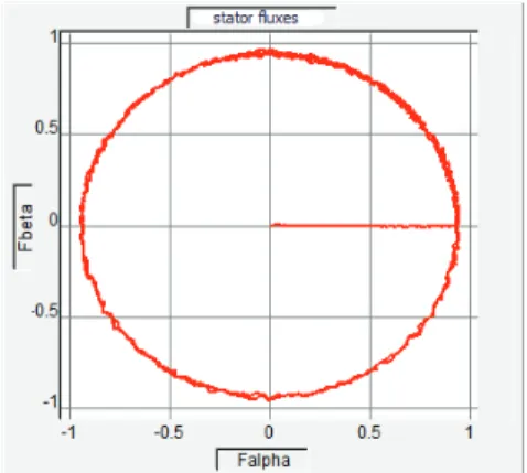
has a large ripple around these hysteresis limits. Machine pre-magnetizing to the nominal flux is provided by voltage vector in α axes (a phase) in order to avoid high starting currents. After the machine pre-magnetizing, torque demand command is released. Fig. 4 shows circular trajectory of stator flux vector in
αβreference frame.
Fig. 4 – Circular trajectory of stator flux vector.
4 Analysis
of
Possibilities
of Torque Ripple Reduction
Papers [9] and [10] show that torque ripple reduction with constant switching frequency is possible by adaptive hysteresis band modification depending on the applied voltage vector. Literature [11] proposes the torque ripple reduction by using the combination of three out of seven voltage vectors during each sampling period.
Unlike the aforementioned methods, hysteresis band modification and adjustment of voltage vector intensity was analyzed in this paper. At the end, modified hysteresis comparator with 6 non-zero voltage vectors with changing intensity was proposed in order to reduce the torque ripple.
4.1 Hysteresis band changing
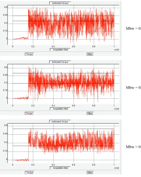
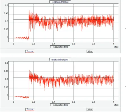
Fig. 5 shows the estimated torque in case of changing the torque hysteresis band with the torque reference set at 0.4 Nm.
around lower hysteresis limit. When the estimated torque is below the lower hysteresis limit, the voltage vector for increase of torque is applied. Similarly, when the estimated torque is within hysteresis limits, zero voltage vector is applied. Although the torque ripple is reduced, the obtained average torque value is less than the torque reference and does not reach it, which could degrade the drive performance.
Mbw = 0.1 Nm
Mbw = 0.2 Nm
Mbw = 0.3 Nm
4.2 Voltage vector intensity adjustment
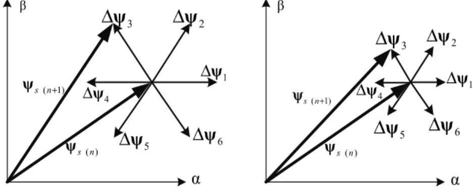
The presence of large torque and current ripple is the result of full value of the voltage vector (when demand for increase or decrease of torque is active) and hysteresis band (when zero vector is applied). However, if variation in intensity of the six non zero voltage vectors is possible, the stator flux increase in the next sampling period will also be variable, as shown in Fig. 6.
( ) s n ψ 1 Δψ 2
Δ
ψ
3Δ
ψ
5Δ
ψ
Δ
ψ
6( ) s n ψ 1 Δψ 2
Δ
ψ
3Δ
ψ
5Δ
ψ
Δ
ψ
6( 1)
s n+
ψ
4
Δψ
4
Δψ ψs n(+1)
β β
α α
Fig. 6 – Stator flux increase for different voltage vector intensities.
The proposed intensity variation of the six non-zero voltage vectors is based on application of PWM modulation. Each of the six voltage vectors can be adjusted from zero to full value. In this way, instead of having a switching element turned on or off during entire sampling period, it is possible to define the time of its on/off state during this period. This allows defining six non-zero voltage vectors with different intensities, which will be applied to the motor (Fig. 1). The switching frequency becomes constant, involving PWM module of the DSP. In this way it is possible to analyze the DTC drive performance with variable discrete voltage vectors without changing the basic control algorithm principle. Fig. 7 shows the influence of six different voltage vector intensities to the torque ripple.
voltage vector
100%
voltage vector 90%
voltage vector 80%
voltage vector 60%
voltage vector 50%
Fig. 7 – Estimated torque response for different voltage vector intensities.
4.3 Hysteresis comparator modification
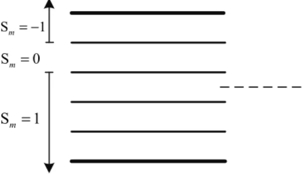
To provide the use of voltage vectors with variable intensities, a modified hysteresis comparator is proposed. Instead of three level torque comparator (Fig. 2) it is necessary to form multilevel comparator. Fig. 8 shows modified multilevel comparator, with signals from the three-level comparator shown on the left hand side of the arrows.
Sm= −1
Sm=0
Sm=1
In this case comparator is divided into 5 segments with equal width. If estimated torque takes value out of hysteresis band, the largest voltage vector will be applied (vector 3). In this way, depending on torque error, voltage vector of appropriate intensity will be selected. Voltage vector direction remains defined with Table 1, depending on flux and torque demands, keeping control algorithm simple.
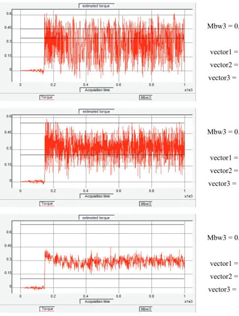
Mbw3 = 0.1 Nm
vector1 = 40%
vector2 = 80%
vector3 = 100%
Mbw3 = 0.3 Nm
vector1 = 40%
vector2 = 80%
vector3 = 100%
Mbw3 = 0.6 Nm
vector1 = 40%
vector2 = 80%
vector3 = 100%
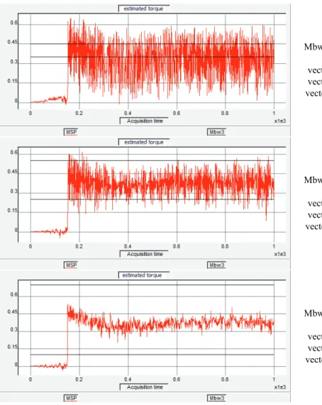
Fig. 9 shows torque response for three different hysteresis bands: 0.1 Nm, 0.3 Nm and 0. Nm, respectively, with three voltage vectors according to Fig. 8. It can be noticed that the torque ripple decreases as hysteresis band increases.
Influence of this hysteresis modification on torque ripple was analyzed using three voltage vector intensities: 40%, 80% and 100%. Estimated torque is shown in Fig. 9 for three different hysteresis bands and the same torque reference of 0.4 Nm.
When the hysteresis band is wider the estimated torque often takes values in the hysteresis range with different intensities of corresponding voltage vector. In this way it is possible to reduce torque ripple. Nevertheless, quick torque response is maintained for large values of torque error when full voltage vector is applied.
The disadvantage of the conventional hysteresis comparator is that the electromagnetic torque decreases when zero voltage vector is applied. In such cases, angle between stator and rotor vector flux decreases and consequently electromagnetic torque decreases too. Fig. 5 shows decreasing of torque during zero voltage vector which proves previous assumption. This is especially evident in case of low power motors with low value of rotor time constant. Therefore, zero voltage vector can be referred to as the vector that decreases torque. Consequently the average value of electromagnetic torque is lower than the torque reference. Modified hysteresis comparator can reduce consequences of this drawback if vector intensities are appropriately rearranged in hysteresis comparator as shown in Fig. 10.
Sm= −1
Sm =0
Sm=1
Fig. 10 – Reallocation of voltage vectors in modified hysteresis comparator.
Mbw3 = 0.1 Nm
vector1 = 40% vector2 = 80% vector3 = 100%
Mbw3 = 0.3 Nm
vector1 = 40% vector2 = 80% vector3 = 100%
Mbw3 = 0.6 Nm
vector1 = 40% vector2 = 80% vector3 = 100%
Fig. 11 – Estimated torque response for modified hysteresis comparator and relocated voltage vectors.
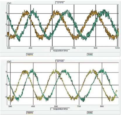
Fig. 11 confirms advantages of this method with modified hysteresis com-parator and adjustable voltage vectors. The torque ripple is significantly reduced and its average value corresponds to the reference value of 0.4 Nm. Also, lower level of acoustic noise is noticed as a consequence of torque and current ripple reduction (Fig. 12).
Fig. 12 – Stator currents with classic DTC (top) and with proposed DTC method (bottom).
With only three different voltage vector intensities torque and current ripple are reduced by three times, compared to the results with full voltage vector. In this way, by analogy, it is possible to define higher number of voltage vectors and hysteresis comparator with higher number of segments. This will further contribute to the torque ripple reduction.
5 Conclusion
vector intensity and the flux and torque errors to achieve maximum torque ripple reduction with minimum number of segments in the comparator.
6 Acknowledgement
This paper is a result of activities within the project TR33016 which is supported by Ministry of Education and Science and Technological Development of Republic Serbia.
7 Literature
[1] I. Takahashi, T. Noguchi: A New Quick-response and High-efficiency Control Strategy of
Induction Motor, IEEE Transaction on Industry Applications, Vol. IA-22, No. 5, Sept. 1986, pp. 820 – 827.
[2] P. Matić, B. Blanuša, S.N. Vukosavić: Direct Torque Control and Field Oriented Control in
μC Drives, INFOTEH, Jahorina, Republic of Srpska, BIH, 25 – 27 March 2002, Vol. 2, Ref.
D-2, pp. 227 – 231.
[3] P. Vas: Sensorles Vector and Direct Torque Control, Oxford University Press, NY, USA,
1998.
[4] V.N. Katsikis: MATLAB - A Fundamental Tool for Scientific Computing and Engineering
Applications - Volume 1, InTech, Rijeka, Croatia, 2012.
[5] S. Belkacem, F. Naceri, R. Abdessemed: Reduction of Torque Ripple in DTC for Induction
Motor using Input-output Feedback Linearization, Serbian Journal of Electrical Engeneering, Vol. 8, No. 2, May 2011, pp. 97 – 110.
[6] P.L. Jansen, R.D. Lorenz: A Physically Insightful Approach to the Design and Accuracy
Assessment of Flux Observers for Field Oriented Induction Machine Drives, IEEE Transaction on Industry Applications, Vol. 30, No. 1, Jan/Feb. 1994, pp. 101 – 110.
[7] N.T. West, R.D. Lorenz: Digital Implementation of Both a Stator and Rotor Flux Linkage
Observer and Stator Current Observer, 42nd IEEE Industry Applications Society Annual Meeting, New Orleans, LA, USA, 23 – 27 Sept. 2007, pp. 1001 – 1007.
[8] Technosoft MCK2812 Technical Data and User Manual. Available Online:
http://www.technosoftmotion.com/en/tools/professional-kits-with-apps/induction-motor-control-kits/mck2812-kit-c-pro-s-im
[9] H.I. Okumus, M. Aktas: Adaptive Hysteresis Band Control of Constant Switching
Frequency in DTC Induction Motor Drives, Turkish Journal of Electrical Engineering and Computer Sciences, Vol. 18, No. 1, Jan. 2010, pp. 59 – 69.
[10] J.K. Kang, D.W. Chung, S.K. Sul: Direct Torque Control of Induction Machine with
Variable Amplitude Control of Flux and Torque Hysteresis Band, Electric Machines and Drives, International Conference Electric Machines and Drives, Seattle, WA, USA, 09 – 12 May 1999, pp. 640 – 642.
[11] F. Khoucha, K. Marouani, A, Kheloui, K. Aliouane: A DSP-based Discrete Space Vector