Study of Energy Losses in High-Voltage Induction
Motor Electric Drive
Svilen Rachev, Cornelia Anghel Drugarin, Konstantinos Karakoulidis, Ivaylo Dimitrov, Lyubomir Dimitrov
The dynamic behavior during operation of the high-voltage induction motor electric drive has been studied by means of mathematical model developed. The purpose is to draw out more clearly picture of operation of high-voltage induction motor drives. The system of differential equations has been transformed and solved using suitable software. As a result the values ofthe energy losses components in the induction motor have been obtained according to different values of supply voltage and factor of inertia. Some of the study results have been presented graphically. An analysis has been made and conclusions from the results obtained have been done.
Keywords: high-voltage techniques, induction motor drives, electric
machines, modeling, energy conversion
1. Introduction
Induction motors form the basis of modern electric drives. The drive of a number of industrial units require electric motors with high power - 500, 800, 1000 kW and more. Usually induction motors with such power are high voltage - 6,000 or 10,000 V.
In order to have more clearly picture on operation of induction motors it is necessary to study the mechanical and electrical phenomena of dynamic behavior arisen. Important characteristics of induction motors are the starting torque, the maximum torque, and the torque-speed curve [Rizzoni, 1993].
Very often in transient processes there are large currents. They usually subside very quickly, but their maximum values are very large. Current amplitude in the transient process called impact current. Serving as a given that the mechanical forces within the windings are proportional to the square of the current, it becomes clear need to determine the currents during transient
ANALELE UNIVERSITĂŢII
processes and hence knowledge of the process itself. Given that the impact current is much larger than rated one, it is clear that there will be forces that have large values and acting mostly on the butt joints.
Paper deals with performance of pump high-voltage electric drive as applica-tion of inducapplica-tion motor in manufacturing processes of technological cycles from energy efficiency point of view. The emphasis is on working together on the production mechanism and drive electric motor by examining the overall electromechanical system.
2. Mathematical model
Mathematical model is proposed for the study of transient processes and steady-state operation of pumps electric drive. The equations for the voltages of the stator and rotor windings of the induction motor are presented in a coordinate system which rotates at a synchronous speed and they are expressed in relative units. In studies we use the parameters of the T-shaped equivalent circuit of the motor which are determined by calculation methodology of the manufacturing company for value of slip s = 1. Parameters of the electric equivalent circuit are active and inductive resistances of one phase of the electric motor.
The driven mechanism is presented by means of a single-mass dynamic model.
We transform the three-phase system into a two-coordinate system. The equations for the voltages of the windings of the induction machine are represented in a coordinate system rotating at the synchronous rotational speed. Using this coordinate system provides the convenience that the system of differential equations attend important parameter of the induction machine slips.
The complete system of differential equations representing mathematical model of electromechanical system of electric drive for pump unit consists of five equations. After converting equations for voltages of windings and presenting expressions received in the form of Cauchy, for ease of solving them, we get four equations to model stator currents. Fifth equation is fundamental relationship between torques, so called equation of motion[Crowder, 2006]. It includes torque developed by the electric motor and resisting torque of the pump unit.
The torque-speed characteristics of pumps are often approximately represented by assuming that the torque required is proportional to the square of the speed, giving rise to the terms ‘square-law’ load [Hughes, 2006].
The total moment of inertia of the electric drive ITOT is set by means of factor of inertia FI as
r
TOT FI I
I = ×
, (1)
where
We introduced the name of multiplicity of supply voltage as
rated
V V V
K = /
, (2)
where
V current value of supply voltage,
rated
V nominal value of supply voltage.
The analysis of the transient processes in the induction motor is carried out with the generally accepted assumptions [Rachev, 2004].
In studies we accept the following assumptions and simplifications: it is assumed that the motor operates with a unsaturated magnetic system and there is proportionality between the current and the magnetic flux; currents, e.m.f. and magnetic flux are sinusoidal; the parameters accepted are permanent; the stator and rotor windings are symmetrical, while the air gap is uniform.
Furthermore, it is assumed that the induction motor is connected to a symmetrical, three-phase power supply source. The limiting factor is normally the allowable temperature rise of the windings [Rachev S., K. Karakoulidis, 2014].
It should be understood that different design groups and different authors have different ways of handling losses in induction machines which have proved satisfactory in their own work [McPherson, 1990].
The same author points out and the following: 'Do not assume in any porblem in the practice of engineering that the device you are studying is operating at the rated values given on the nameplate' [McPherson, 1990].
We analyze the behaviour of the machine both from the stator and rotor posi-tion. Induction motor transforms electrical energy loaded from power supply mains to the stator into mechanical energy received at the rotor shaft. Moreover this energy conversion is accompanied by losses. The equation of the active power balance can be written as [Sukmanov, 2001; McPherson, 1990; Merz, 2002]
2 2
1 1
1
P
P
P
P
P
P
P
=
∆
e+
∆
M+
∆
e+
∆
МЕCH+
∆
ADD+
, (3) where1 1 1 1
1
m
V
I
cos
ϕ
P
=
(4)– electrical power received from power supply mains to the stator,
1 2 1 1
1
m
I
r
P
e=
∆
(5)– electrical (copper) losses of power related to the heating of the windings of the stator, wherein the current flows in them,
– magnetic losses of power related to steel core of the stator remagnetization (hysteresis losses) and its heating by eddy currents,
' 2 2 2 2
2
m
I
r
P
e=
∆
(7)– electrical (copper) losses of power in rotor windings,
∆
P
МЕCH (8)– mechanical losses of power due to friction in the bearings and rotating parts of air (windage losses),
ADD
P
∆
(9)– additional difficult accounted power losses from eddy currents, determined by the magnetic stray field, by the magnetic flux pulses, by the presence of harmonics (additional losses are
∆
P
ADD≈
0
,
005
P
1NOM),
2
P
– mechanical power on the motor shaft.The electrical losses in the rotor are directly proportional to the slip s [Katsman, 2001]:
EM
e
sP
P
=
∆
2 , (10)where
P
EM – electromagnetic power of the motor)
(
1 11 M e
EM
P
P
P
P
=
−
∆
+
∆
. (11)According to magnetic
∆
P
M1 and mechanical∆
P
МЕCH losses of power, theyare essentially not dependable on the load [Katsman, 2001]. The sum of these losses is roughly constant [McPherson, 1990].
Mechanical losses of power for motors with high power (with outer diameter of the stator Da>0.5 m) are [Kopilov, 1988]
(
)
310 a
T
МЕCH K D
P =
∆ , (12)
7 . 0
=
T
K for motors with pole number 2р=6.
Bearing-friction and windage losses are small as a rule, and may be neglected for rough calculation [Merz, 2002].
equal to the variable losses – electrical (
∆
P
e1 и∆
P
e2). The electrical losses inrotor windings are proportional to the slip and thus induction motors are economical in small slips – 1÷4% [Kopilov, 1988].
It should be noted that with the increase of load useful power increased in proportion to the current, and electrical losses grow in proportion to the square of the current. The efficiency is maximum when permanent losses are equal to vari-able ones. These are magnetic and mechanical losses. Roughly it can be consid-ered that mechanical losses are proportional to the square of the rotational fre-quency. Variable electrical losses are losses that are proportional to the square of the current. When designing electrical machines aim is to get maximum efficiency at 60-80% of the rated load, because electrical machinery continued work with underloading 15-25%. In order to move the peak efficiency in the area of the nominal load or in the overloading area must be increased cross-section of the windings and to reduce the electrical losses in the machine.
The determination of the components of the energy losses is represented below [Karakulidis, 2015].
Energy taken from the mains in starting mode is
( )
[
]
∑
[
( )
]
∑
[
( )
]
∑
− − − = = =+
+
=
1 1 10 0 0 n k n k n k a k n c a k n b a k n a
ST
P
t
P
t
P
t
W
, (13)1
−
n
a – number of point of the time axis, which lasts until the transient
process, k a
P
, k aP
, k aP
– power consumed respectively by phase A, phase B and phase C.Energy taken from the mains at steady-state mode is
(
)
[
]
[
(
)
]
∑
− = −−
−
+
+
=
1 11
n a k n c b a SS n k kk
P
P
n
t
t
P
W
δ
, (14)t
δ
– a discrete of time axis in seconds,n
t
– duration of the transient process in seconds.The energy losses in butt joints (frontal connections) in starting mode are
( ) ( ) ( )
[
]
∑
− =+
+
=
1 0 2 2 2 11
0
.
5
n k k k a k c b a
ST
r
I
I
I
t
W
δ
, (15)1
a
I
,I
b,I
c – phase stator currents.The energy losses in butt joints (frontal connections) in steady-state mode are
( ) ( ) ( )
[
]
∑
−= −
+
+
=
1 2 2 21 1
1
5
.
0
n
a k
c b
a SS
n
k k
k
I
I
t
I
r
W
δ
. (16)The energy of moving parts and effective work in starting mode is
1
2
5 .
0 + −
= TOT b L ban
MMST I T t
W ω ω , (17)
b
ω
– rated circular frequency, TL – resisting moment of the load, Nm.The energy of moving parts and effective work in steady-state mode is
[
]
∑ = −
= −
1
1
n
a k k k MMSS
n t T
W ω δ . (18)
Heat released in motor in starting mode is
MMST ST
HST
W
W
W
=
−
. (20)Heat released in motor in steady-state mode
MMSS SS
HSS
W
W
W
=
−
. (21)3. Results.
Solving of differential equations system which describes the dynamic behavior of pump high-voltage electric drive is a complicated task. Induction motor type AO 710 L-66 is used to drive, whose technical data and parameters at slip s = 1 are given in the Appendix.
0.00 0.50 1.00 1.50 2.00 2.50 3.00 3.50 4.00 4.50 5.00
0.90 0.95 1.00 1.05 1.10
T h e e n e rg y lo s s e s in b u tt j o in ts W H S T , x 1 0 6 J o u le
Factor of Inertia FI
Kv=0.90 Kv=0.95 Kv=1.00 Kv=1.05 Kv=1.10
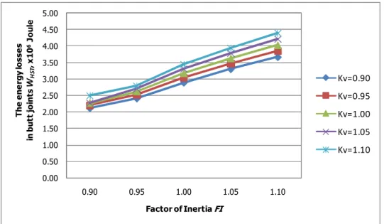
Figure 1. The energy losses in butt joints W1ST in starting mode versus factor of inertia FI.
0.00 0.50 1.00 1.50 2.00 2.50 3.00 3.50 4.00 4.50 5.00
0.90 0.95 1.00 1.05 1.10
H e a t re le a s e d in m o to r in s ta rt in g m o d e W 1 S T , x 1 0 1 1J o u le
Factor of Inertia FI
Kv=0.90 Kv=0.95 Kv=1.00 Kv=1.05 Kv=1.10
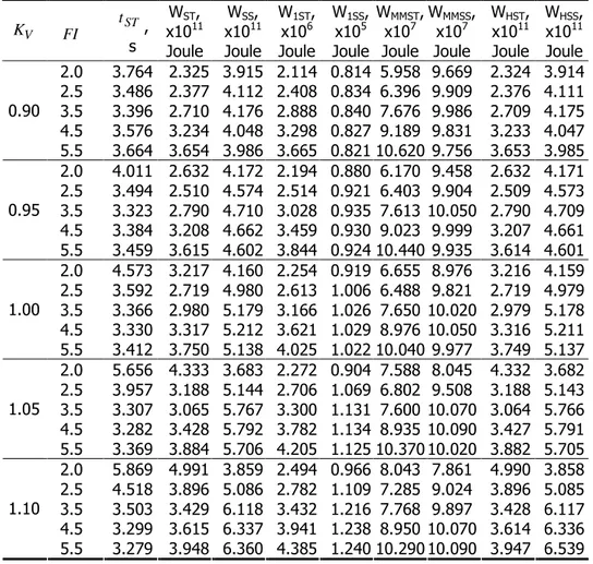
Table 1. Influence of multiplicity of supply voltage and factor of inertia
* tSTis staring time in seconds.
4. Conclusion
The mathematical model developed helps to study processes during start and steady-state operation of the pump mechanism driven by means of high-voltage motor and further define the components of the energy losses.
As a result of simulation studies we evaluate the influence of the supply voltage and the electric drive total moment of inertia on starting time and the components of the energy losses of a powerful electric motor to pump unit. It is necessary to bear in mind that the electric motors operation at higher heating
V
K FI tST,
s
WST,
x1011 Joule
WSS,
x1011 Joule
W1ST,
x106 Joule
W1SS,
x105 Joule
WMMST,
x107 Joule
WMMSS,
x107 Joule
WHST,
x1011 Joule
WHSS,
x1011 Joule 2.0 3.764 2.325 3.915 2.114 0.814 5.958 9.669 2.324 3.914 2.5 3.486 2.377 4.112 2.408 0.834 6.396 9.909 2.376 4.111 3.5 3.396 2.710 4.176 2.888 0.840 7.676 9.986 2.709 4.175 4.5 3.576 3.234 4.048 3.298 0.827 9.189 9.831 3.233 4.047 0.90
5.5 3.664 3.654 3.986 3.665 0.821 10.620 9.756 3.653 3.985 2.0 4.011 2.632 4.172 2.194 0.880 6.170 9.458 2.632 4.171 2.5 3.494 2.510 4.574 2.514 0.921 6.403 9.904 2.509 4.573 3.5 3.323 2.790 4.710 3.028 0.935 7.613 10.050 2.790 4.709 4.5 3.384 3.208 4.662 3.459 0.930 9.023 9.999 3.207 4.661 0.95
5.5 3.459 3.615 4.602 3.844 0.924 10.440 9.935 3.614 4.601 2.0 4.573 3.217 4.160 2.254 0.919 6.655 8.976 3.216 4.159 2.5 3.592 2.719 4.980 2.613 1.006 6.488 9.821 2.719 4.979 3.5 3.366 2.980 5.179 3.166 1.026 7.650 10.020 2.979 5.178 4.5 3.330 3.317 5.212 3.621 1.029 8.976 10.050 3.316 5.211 1.00
5.5 3.412 3.750 5.138 4.025 1.022 10.040 9.977 3.749 5.137 2.0 5.656 4.333 3.683 2.272 0.904 7.588 8.045 4.332 3.682 2.5 3.957 3.188 5.144 2.706 1.069 6.802 9.508 3.188 5.143 3.5 3.307 3.065 5.767 3.300 1.131 7.600 10.070 3.064 5.766 4.5 3.282 3.428 5.792 3.782 1.134 8.935 10.090 3.427 5.791 1.05
5.5 3.369 3.884 5.706 4.205 1.125 10.370 10.020 3.882 5.705 2.0 5.869 4.991 3.859 2.494 0.966 8.043 7.861 4.990 3.858 2.5 4.518 3.896 5.086 2.782 1.109 7.285 9.024 3.896 5.085 3.5 3.503 3.429 6.118 3.432 1.216 7.768 9.897 3.428 6.117 4.5 3.299 3.615 6.337 3.941 1.238 8.950 10.070 3.614 6.336 1.10
temperature of stator winding leads to a decrease in their reliability and durability. The change of total moment of inertia ITOT has a significant impact not only on the duration of transient processes but also the energy losses. At invariably supply voltage with increasing of FI starting time decreases and the energy losses in butts and the heat released in motor increase. As optimal value for this motor proves that for total moment of inertia on FI =3.5.
As an overall assessment of the impact of the supply voltage on the characteristics of induction motor can be concluded that both increase and decrease with respect to the rated value affect adversely. Dependencies of the energy losses as a function of the supply voltage also have great practical significance when considering the issues of starting and possibly control the speed of high-voltage induction motors.
5. Appendix
Induction motor data and equivalent circuit parameters
Description Data
Rated power (Prated) 2850 kW
Rated stator voltage (Vrated) 6000 V
Operating frequency (f) 50 Hz Line stator current (I1) 335.841 A Rated torque (Trated) 27442 Nm
Pole pair number 3
Rotor speed (Nr) 992.263 rpm
Power factor 0.845
Rotor torque of inertia (Ir) 275 kgm2 Stator resistance r1 0.05 Ω Rotor resistance r2' 0.062 Ω Stator leakage reactance x1 0.957 Ω Rotor leakage reactance x2' 2.237 Ω
Magnetizing reactance xm 34.826 Ω
References
[1] Crowder R., Electric Drives and Electromechanical Systems, Oxford, U.K., Elsevier, 2006, 35-42.
[3] Katsman, M.M., Electrical machines. Academia, Moscow, 2001.
[4] Karakulidis K., Transient Processes and Dynamic Loadings in Electrical Machines for Mechanisms with Impact Loadings, PhD Thesis, Department of Electrical Engineering, Technical University Gabrovo, Bulgaria, 2015. [5] Коpilov I.P., et al. Design of electrical machines, Sofia, Tehnika, 1988. [6] McPherson G.; Laramore R.D., An Introduction to Electrical Machines
and Transformers, 2nd ed, John Wiley & Sons, Inc., New York, USA. 1990. [7] Merz H., Electrical Machines and Drives. VDE VERLAG GMBH, Berlin,
Germany, 2002.
[8] Rachev S.R., Transient Processes and Dynamic Loads in Induction Ma-chines for Lifting Mechanisms, PhD Thesis, Department of Electrical Engineering, Technical University - Gabrovo, Bulgaria, 2004.
[9] Rachev S., Karakoulidis K., Research on Energy Losses in Electric Induction Motor for Forging Fly-Press Drive, Proceedings on XXII Interna-tional Conference ‘Ecological Truth’ EcoIst ’14, Bor, Serbia, 2014. pp.131-136.
[10] Rizzoni G., Principles and Applications of Electrical Engineering. Richard D. Irwin, Inc., Burr Ridge, Illinois, USA. 1993.
[11] Sukmanov V.I., Electrical machines and apparatus. Kolos, Moscow, 2001.
Addresses:
• Assoc. Prof. Dr. Eng. Svilen Rachev, Technical University of Gabrovo, 4, Hadgi Dimitar str., 5300, Gabrovo, Bulgaria [email protected]
• Ş. L. Dr. Eng. Cornelia Anghel Drugarin, “Eftimie Murgu” University of Reşiţa, Piaţa Traian Vuia, nr. 1-4, 320085, Reşiţa, [email protected] • Dr. Eng. Konstantinos Karakoulidis, Kavala Institute of Technology,
Agios Loukas 65404 Kavala, Greece [email protected] • Eng. Ivaylo Dimitrov, Technical University of Gabrovo, 4, Hadgi Dimitar
str., 5300, Gabrovo, Bulgaria [email protected]