Solidiication behavior and rheo-diecasting
microstructure of A356 aluminum alloy
prepared by self-inoculation method
*Yuan-dong Li
Male, born in 1971, Ph. D, Professor. His research mainly focuses on the semisolid metal processing of nonferrous alloys.
E-mail: [email protected]
Received: 2016-07-19; Accepted: 2016-10-25
Ming Li 1, *Yuan-dong Li 1,2, Xiao-feng Huang 1,2, Chi Cao 1,2, and Ying Ma 1,2
1. State Key Laboratory of Advanced Processing and Recycling of Nonferrous Metals, Lanzhou University of Technology, Lanzhou 730050, China;
2. Key Laboratory of Non-ferrous Metal Alloys and Processing, Ministry of Education, Lanzhou University of Technology, Lanzhou 730050, China
S
emisolid metal processing has been widely recognized by experts and scholars since it wasirst developed, and is regarded as the most promising
processing technology in the 21st Century [1, 2]. In the
semisolid forming process, the remaining liquid phases
of alloy can be connected with each other due to the existence of non-dendritic solidification structures in
the semisolid slurry, which can effectively reduce or even eliminate solidification shrinkage. Meanwhile, the viscosity of semisolid slurry is higher than liquid, making the gas less involved. Therefore, in theory, using
semisolid forming technology can obtain the products
Abstract:
Semisolid slurry of A356 aluminum alloy was prepared by self-inoculation method, and themicrostructure and solidiication behavior during rheo-diecasting process were investigated. The results indicate
that the semisolid slurry of A356 aluminum alloy can be prepared by self-inoculation method at 600 °C. Primary
α-Al particles with ine and spherical morphologies are uniformly distributed when the isothermal holding time of
slurry is 3 min. Liquid phase segregation occurs during rheo-diecasting process of semisolid slurry and the primary
particles (α1) show obvious plastic deformation in the area of high stress and low cooling rate. A small amount
of dendrites resulting from the relatively low temperature of the shot chamber at the initial stage of secondary solidiication are fragmented as they pass through the in-gate during the mould illing process. The amount of dendrite fragments decreases with the increase of illing distance. During the solidiication process of the remaining liquid, the nucleation rate of secondary particles (α2) increases with the increase of cooling rate, and the content of
Si in secondary particles (α2) are larger than primary particles (α1). With the increase of cooling rate, the content of
Si in secondary particles (α2) gradually increases. The morphologies of eutectic Si in different parts of die casting
are noticeably different. The low cooling rate in the irst illing positions leads to coarse eutectic structures, while the high cooling rate in the post illing positions promotes small and compact eutectic structures.
Key words:
semisolid; self-inoculation method; secondary solidification; dendrite fragments; primary particles; eutectic structureCLC numbers: TG146.21 Document code: A Article ID: 1672-6421(2017)01-001-09
without hole defects [3-5]. After more than 40 years
of exploration and research, scholars successively developed preparation processes of semisolid microstructure, such as Semi-solid Rheocasting (SSR)
[6], Continuous Rheoconversion Process (CRP) [7],
New Rheocasting Process (NRC) [8], and Swirled for
Equilibration device (SEED) [9], etc. Based on the
characteristics of low superheat pouring, liquid-liquid mixed casting, solid-liquid mixed casting, suspension casting and inclined cooling method, a new type of solidiication structure control method, self-inoculation method (SIM) [10], is proposed. The process involves
mixing liquid alloy with the solid alloy of the same composition (self-inoculants), and subsequently pouring
the melt into a mold through a multi-stream fluid director. Heterogeneous nucleation is enhanced due to
the addition of self-inoculants (primary inoculation), and
Table 1: Chemical composition of commercial A356 alloy (wt.%)
Si Mg Fe Ti Cu Zn Al
7.06 0.27 0.115 0.097 0.001 0.01 Balance
of the cooling channel (secondary inoculation), resulting in high grain density and small grain size in solidiication structure.
Semisolid metal rheological forming is a direct forming
method using solid-liquid mixed slurry with two solidiication processes. The process of slurry preparation (solid particles precipitate from liquid alloy) is called primary solidification, and the solidification process of slurry in the subsequent forming (solidiication of remaining liquid) is called secondary solidification. In recent years, the study of semisolid metal rheological forming mainly focused on primary solidiication,
while the research of secondary solidification seldom can be found. Fan et al. [11] investigated the shearing effect on
solidification characteristics of remaining liquid in A357 aluminum alloy semisolid slurry, and found that the intensive shearing not only influenced the primary solidification, but
also the secondary solidification. Li et al. [12] studied the microstructural characteristic and secondary solidification
behavior of AZ91D magnesium alloy prepared by thixoforming, and proposed that the secondary solidiication process involved three stages: the growth of primary α-Mg particles, remaining liquid solidified by re-nucleation and growth, and eutectic
reaction. Chen et al. [13] investigated the secondary solidiication
behavior of AA8006 alloy prepared by suction casting, and
determined that the cooling rate influenced not only the
solidiication of primary α-Al dendrite, but also the secondary solidiication process of the remaining liquid.
Previous studies have indicated that the solidification of remaining liquid in semisolid slurry has an important inluence
on the final solidification microstructures and the mechanical
properties of the alloy. Therefore, it is necessary to study the precipitation behavior of the secondary particles in the remaining liquid of the slurry, the eutectic reaction, and their microstructural characteristics. Based on the previous research
[14-17], a thin-walled discal casting of A356 aluminum alloy
was produced combining semisolid slurry preparation by self inoculation method with traditional high-pressure die casting.
Microstructures of both primary solidification and secondary solidification in different forming parts were analyzed. The relationship between diferent illing positions and liquid phase
segregation was explored by comparing the morphologies and
solid fractions of primary particles in diferent forming positions. Solidiication behavior of remaining liquid in rheo-diecasting of A356 aluminum alloy was elaborated by quantitative analysis of secondary particles and the Si morphologies in diferent forming positions, in order to provide theoretical reference and technical
guidance for rheo-diecasting application of A356 aluminum alloy.
1 Experimental procedures
1.1 Preparation of self-inoculants
Commercial A356 alloy (Table 1) was melted in a pit-type electric resistance furnace. The melt was degassed by C2Cl6
(1mass% of alloy) at 720 °C, then cooled to 700 °C and poured
into a metal mold to obtain metal bars with the size of Φ15
mm×150 mm. Then the bars were machined into small portions
with sizes of about 5 mm×5 mm×5 mm.
1.2 Slurry preparation and determination of
optimum parameters
Figure 1 shows the schematic diagram of slurry preparation by
SIM (self-inoculation method). The luid director was inclined at 45° with a length of 500 mm. The commercial A356 alloy was melted in an electric resistance furnace, and degassed by C2Cl6
(1mass% of alloy) at 720 °C, then the self-inoculants (5mass% of alloy) were added into the melt at 680 °C and stirred quickly. The mixed melt was collected through the luid director to the collector to obtain the semisolid slurry. Finally, the prepared slurry was held for a certain time (0 min, 3 min, 5 min and 10 min, respectively) at 600 °C, and then directly poured into cold water to obtain water quenched specimens. Specimens were polished and etched by saturated NaOH aqueous solution. The optimum holding time was determined by measuring the average particle size (D=(4A/π)1/2, where A is area of the particle) and shape factors [F= P2/(4πA), where P is the perimeter of particle]
of primary particles using image analysis software Image-Pro Plus 5.0.
Fig. 1: Schematic diagram of slurry preparation by self-inoculation method
1.3 Microstructure observation and
quantitative analysis
The re-prepared A356 alloy semisolid slurry under the
optimized parameters was chosen to conduct the rheo-diecasting
experiment of thin-walled casting using DAK-450 die casting machine. The dies were preheated to 200 °C by hot circulating oil and the shot chamber was preheated to 300 °C. The injection rate was 1.2 m•s-1 with a pressurization of 160 MPa.
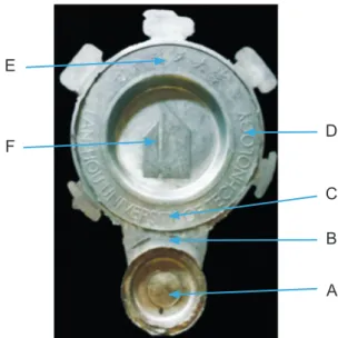
A photograph of the die casting with a diameter of 200 mm and
a wall thickness of 2 mm is shown in Fig. 2. Forming process and solidification behavior of rheo-diecasting were studied
Fluid director
Fluid director
Fig. 2: Semi-solid die casting and sampling positions: biscuit (A); in-gate (B); bottom (C); middle (D); top (E) and centre (F)
by microstructures of diferent positions shown in Fig. 2. The specimens were prepared by the standard technique of grinding with SiC abrasive paper and polishing with an Al3O2 suspension
solution, followed by etching in saturated NaOH aqueous solution. The FEG450 scanning electron microscopy (SEM) was carried out with an energy dispersive spectroscope (EDS) and operated at an accelerating voltage of 3-20 kV to observe the morphologies of secondary particles and eutectic structures.
2 Results and discussions
2.1 Slurry microstructures under different
holding times
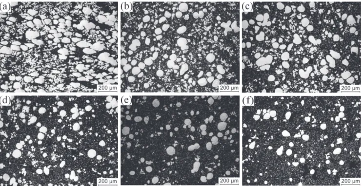
Figure 3 shows the water quenched microstructures of A356
aluminum alloy semisolid slurry after holding at 600 °C for
0 min, 3 min, 5 min and 10 min, respectively. It shows that
the semisolid slurry of A356 aluminum alloy containing
rose-shape and ine dendritic primary particles can be prepared by SIM, as shown in Fig. 3(a). After holding for a short time, the dendritic arms of primary particles are fused, and primary particles become spherical, as shown in Fig. 3(b) and (c). But when the holding time of slurry is too long (such as 10 min),
the sizes of the primary particles gradually increase while the
merge phenomenon among primary particles becomes obvious, which leads to the appearance of “8” shaped and “spindle-like” structures, as shown in Fig. 3(d).
Figure 4 shows the effect of different holding times on
average particle size and shape factor at the same holding temperature (600 °C). It is found that the size of the primary
particles increases with the extension of the holding time.
The shape factor of the primary particles is close to 1 and the average size is relatively small when the holding time is 3 min. Therefore, the semisolid slurry isothermal holding for 3 min
is chosen as the slurry preparation parameter for the semisolid rheo-diecasting experiment .
Fig. 3: Water quenched microstructures of A356 aluminum alloy semisolid slurry at 600 °C for different isothermal holding times: 0 min (a), 3 min (b), 5 min (c), 10 min (d)
A B C D E
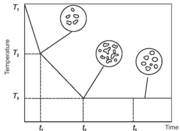
Precipitation of nucleus by adding self-inoculants into the melt; (2) Formation of large number of nuclei when the melt lows through the luid director; (3) Spheroidization of primary particles during
the isothermal holding process.
2.2 Primary particles (α
1) in different positions
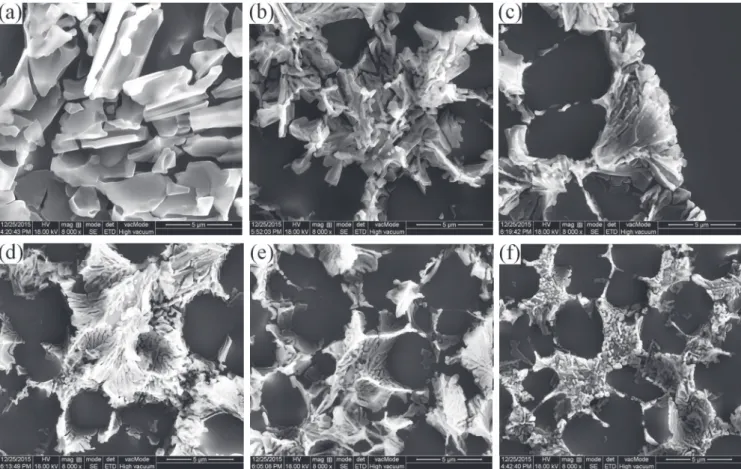
Figure 6 shows the microstructures of rheo-diecasting indiferent positions with the slurry isothermal holding at 600 °C for 3 min. The illing order of semisolid slurry during die casting is from A to F (Fig. 2). It can be seen that the amount of primary particles, average particle size and solid fraction are gradually
decreased from A to F.
All the solidification microstructures in different positions
are composed of spherical primary particles (α1), secondary
particles (α2), some dendrite fragments and eutectic structures.
The α1 particles are uniformly distributed in the solidified
structure. The dendrite fragments are formed when pouring the slurry into the shot chamber, and α2 particles are formed in
remaining liquid phase when the slurry is illing the cavity [11,19].
It can be seen that the solidification microstructures of A356
aluminum alloy in diferent positions of die casting are noticebly different. In position A, primary particles have large plastic deformation and bond with each other, and there are a lot of small dendritic crystals around them (Fig. 6a). In position B (Fig. 6b) and position C (Fig. 6c), the majority of primary particles are spherical, with a small number of irregular particles, and the
dendrite fragments around the primary particles are smaller than
in position A; while in positions D, E and F, primary particles
are uniformly distributed and the dendrite fragments around them are fewer and smaller.
In order to further describe the microstructural characteristics
in different positions, average particle size, shape factor and solid fraction of the primary particles in diferent positions are measured, as shown in Table 2. It can be seen that the amount of primary particles, average particle size and solid fraction are gradually decreased from A to F, mainly due to the formation of liquid phase segregation, different cooling rate during the illing process and decreased illing pressure from position A to
position F.
It is well known that liquid metal forming mainly depends on the liquid phase low, while the semisolid metal forming not only
Fig. 4: Curves of shape factor and average particle size during holding process
Fig. 5: Stage schematic of spherical particles formation during semisolid slurry preparation by SIM
After adding the self-inoculants, the temperature of the A356 aluminum alloy melt will decrease rapidly. As a result, there will
be a large number of high melting points in the local position of
the melt, which will be used as the nucleation substrates. When the melt lows through the luid director, the solidiied shell is formed rapidly under the chilled director surface. Subsequently, free grains and dendrite fragments are formed and involved in the melt when the subsequent melt scours and strongly shears the solidiied shell, and inally evolves into rose-shape and ine dendritic primary particles. At the end of the director, turbulence occurs when two melt streams are converged, which promotes
the thermal field and concentration field of the melt to be
uniform. It can be seen from Fig. 3(a) that the water quenched microstructure of semisolid slurry contains rose-shape and ine
dendritic primary particles when the slurry is directly poured into
the cold water without isothermal holding. During the isothermal holding process, the dendrite roots are fused due to enrichment of the solute, which leads to the formation of single irregular particles, and then the tips of these irregular particles are melted. At the same time, the increased number of particles increases the interfacial energy. Primary particles, as the substrates to absorb solute atoms from liquid phase, are rounded and spherical under the influence of the driving force so that the interfacial energy can be reduced as far as possible. Consequently, primary
particles are increased and spheroidized with the extension of
isothermal holding time. However, different sizes of original
dendrite fragments result in different diameters of spherical
primary particles after isothermal holding for a short time. The solute concentration of liquid phase around smaller particles is lower than that around larger particles.With the further extension of the holding time, Si elements will continue to diffuse from large particles to small particles, while the Al elements have the opposite diffusion path. As the result, large particles become larger and small particles become smaller, and even melting and disappearing, which is called Ostwald ripening [18]. The
“8” shaped and “spindle-like” structures are formed as the
intensification of merge phenomenon in the late stage of the
isothermal holding process. Therefore, the process of semisolid slurry preparation by SIM can be divided into 3 stages (Fig. 5): (1)
Time
Table 2: Average particle size, shape factor and solid fraction of primary particles in different positions of casting
Position of primary αNumber
1
Average
particle size (μm) Shape factor
Solid fraction (%)
A 72 73.32 1.63 35.6
B 54 63.37 1.36 25.8
C 53 63.17 1.32 24.9
D 40 55.48 1.25 19.9
E 38 55.31 1.23 18.6
F 32 47.83 1.23 10.6
Fig. 6: Microstructures in different positions of die casting: biscuit, A (a); in-gate, B (b); bottom, C (c); middle, D (d); top, E (e); centre, F (f)
depends on the liquid phase low but also the solid phase low and deformation of primary particles in semisolid slurry. The
rheological forming process of semisolid slurry includes four
kinds of low mechanisms: liquid phase low mechanism, liquid-solid phase mixture low mechanism, slipping mechanism among
solid particles and the deformation mechanism of solid phase [20].
In the situation of present work, liquid phase low mechanism is impossible due to the fast illing speed, and the mainly low mechanism is liquid-solid phase mixture low mechanism during the mould illing process. In this experiment, solid fraction is low (about 27%) so that solid particles are dispersed and diicult to contact with each other in the slurry, which makes it diicult to
start the slipping mechanism among solid particles during the
rheological forming process. However, due to the existence of liquid phase segregation, the amount of solid particles in some areas (such as position A, B and C) are increased, as a result, the slipping mechanism among solid particles can be started. When the filling process is finished, the solidification temperature of position A is higher (because the temperature of the shot chamber is higher than the cavity, and the casting thickness of position A is greater than other positions), where the pressure
is concentrated, so primary particles in this position are easily deformed. Meanwhile, the temperature difference between the shot chamber and dies leads to the diferent cooling rate in diferent positions. Namely, the cooling rate from position A to
position F is gradually increased due to the heat transfer from
high temperature to low temperature. On the other hand, illing
pressure is gradually decreased from position A to position F.
As a result, it does not have enough driving force for primary particles to overcome viscosity of remaining liquid to fill in position F, showing that the amount of primary particles in position F are the least. The results of the comprehensive role of the above shows that the amount of particles and average particle
size of primary particles are gradually decreased from position A
to position F (Table 2).
2.3 Secondary particles (α
2) in different
positions
The rheo-diecasting forming by SIM includes two processes:
primary solidification process and secondary solidification process. Secondary solidification starts when the semisolid
slurry leaves the slurry collector. When the slurry is poured into the shot chamber, heterogeneous nucleation occurs in the remaining liquid and the grains grow into dendrites due to the relatively low temperature of the shot chamber. The dendrites
are fragmented when they pass through the narrow in-gate
illing the cavity with liquid phase, and inally gathering in these
positions.
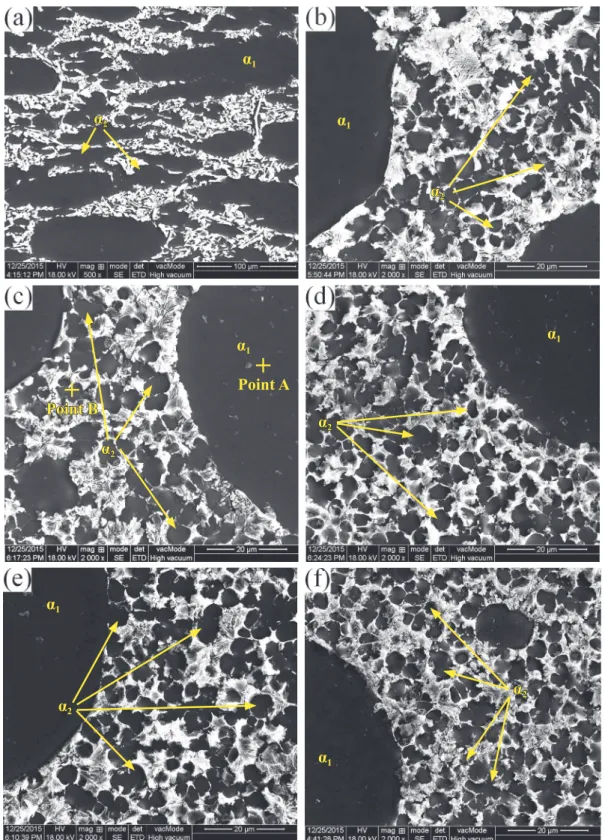
Secondary solidification microstructures in different positions of A356 aluminum alloy rheo-diecasting are shown
in Fig. 7. It can be seen that the morphologies of secondary
particles are mainly fine spherical and rose shape, except for the microstructure in position A, which has relatively large
secondary particles.
Fig. 7: Second solidiication microstructure of rheo-diecasting A356 aluminum alloy in: biscuit, A (a); in-gate,
B (b); bottom, C (c); middle, D (d); top, E (e); centre, F (f)
The thickness of the forming part (from position B to F) in this experiment is 2 mm. During the illing process, the semisolid slurry contacts with the cold mould under high pressure, which can provide a large supercooling. The nucleation rate can be
(1)
expressed as follows:
α
1α
2α
1α
2α
1α
2Point A
+
Point B
+
α
1α
2α
1α
2α
1α
2diffusion activation energy of atoms across the liquid/solid interface, k is the Boltzmann constant, T is thermodynamic
temperature. For most of the alloy melt, the nucleation rate is increased signiicantly when the value of relative supercooling
is between 0.15-0.25 Tm (Tm is the melting temperature of
alloy), which is called “explosive” nucleation. The melting
temperature of A356 aluminum alloy used in this experiment
is about 615 °C, while the dies are preheated to 200 °C and the pouring temperature of the alloy is 600 °C, which provides a large enough relative supercooling for “explosive” nucleation. Therefore, nucleation occurs throughout the whole remaining liquid in thin-walled positions (position B to F). In position A, the thickness and the diameter of the biscuit are larger (40 mm and 80 mm, respectively), which causes most of the nucleation
to occur in the area of the surface due to the chilling of the shot
chamber. According to the Waterloo G [22], the cooling rate R
satisies the following equation:
where h is the heat transfer coefficient, T is the pouring
temperature, T0 is the mould temperature, c is the speciic heat, ρ is the density and z is the thickness of the sample. The value of c is taken as 900 J•(kg•K)-1 and ρ as 2,700 kg•m-3 for aluminum
alloy. The mould temperature is 200 °C and the thickness of the sample is 2 mm. According to Ref.[22,23], the value of h can reach 1.5×10⁴ W•m-2•K-1 for aluminum alloy during the
thin-walled die casting process. Substituting the above values into the equation (2), the cooling rate R can reach 103 K•s-1.
Therefore, the nucleus that formed by “explosive” nucleation
will grow into particularly small secondary particles due to the
large cooling rate (Fig. 7b to 7f). However, in position A, there
are lots of dendrite fragments and primary particles and only a
little remaining liquid phase due to the liquid phase segregation, which leads to fewer nuclei in this position. Meanwhile, nucleus and fragments have enough time to grow due to low cooling rate in this position, making particle sizes (primary particles and secondary particles) larger than other positions.
In order to further explain the differences between the
primary particles and secondary particles in diferent positions,
component analysis of primary particles and secondary
particles are carried out (the measured region as shown in Fig. 7c is similar with point A for primary particles and point B for secondary particles, both are in the center of particles), as
shown in Fig. 8. It can be seen that the contents of Si in primary particles is lower than secondary particles no matter in which
position. In different positions, the contents of Si in both the primary particles and secondary particles are different. The content of Si in primary particles varied between 1.0 and 1.2 and without obvious regularity, while in secondary particles, the
content of Si is gradually increased from position A to position F.
The solid fraction of aluminum alloy A356 at 600 °C is measured to be 27% by Pandat (a thermodynamic calculation software). Assuming that the alloy contains only two kinds of elements, Si and Al (because the contents of other elements are low), the average solid solution of Si in the primary particles is (2)
(3)
Fig. 8: Content of Si in primary particles and secondary particles in different positions
1.13%, which is measured combining equilibrium phase diagram and Pandat. According to the conservation of mass [24], the
composition of the remaining liquid phase, Cl, can be expressed
as:
where C0 is the original content of the alloy, f is solid fraction
and Cs is the composition of the solid phase. According to
equation (3), the content of Al and Si in the remaining liquid phase are 91.7% and 8.3%, respectively, indicating that the composition of the remaining liquid phase are deviated to the eutectic composition (12.6%) compared to the original composition of alloy. The different content of Si between
primary particles and secondary particles indicates that primary particles are precipitated in the original composition of the A356
alloy, while secondary particles are formed in the remaining liquid. During the process of die casting, the rapid cooling rate (103 K•s-1) causing Si atoms enrichment ahead of the interface
and with no time to diffuse, and eventually dissolving in secondary particles. Consequently, the content of Si in secondary particles is higher than primary particles. The calculated value shows that the saturated solid solubility of Si in Al is 1.58%, and the measured content of Si in secondary particles is close to 1.58% (Fig. 8). In position A, the difusion of Si is suicient ahead of solid/liquid interface, which leads to lower
content of Si in the secondary particles of final solidification
microstructure. As the cooling rate increases, the difusion of Si gradually decreases from position B to position F. As the result,
the content of Si is gradually increasing in secondary particles.
2.4 Morphologies of eutectic Si in different
positions
Figure 9 shows the morphologies of eutectic Si in different
Fig. 9: Morphology of eutectic structures in different positions of die casting: biscuit, A (a); in-gate, B (b); bottom, C (c); middle, D (d); top, E (e); centre, F (f)
more closely than position A. In position C, the eutectic structure is small lamellar with transition tendency to ibrous. Most of the eutectic structures are fibrous in position D and E, and there is only a small amount of ine lake, while all the eutectic structures at the center of the die casting (position F) are ine ibrous.
The formation of the intergranular eutectic Si phase between α-Al particles marks the completion of solidiication in the
rheo-diecasting process. Si is a faceted phase and Al-Si eutectic is
usually considered as an irregular eutectic. The morphology of eutectic silicon in as-cast structure is coarse needle-like, which will seriously afect the performance of the alloy, so it is necessary to obtain a ine eutectic silicon structure to improve the mechanical properties of the products. Usually, modiication of the Al-Si eutectic from flake-like to fine fibrous can be achieved by two different ways: by the addition of certain elements (chemical modiication) or with a rapid cooling rate (physical modiication) [11]. In the present study, the eutectic Si in
A356 alloy has been found to undergo a morphological change
from coarse block-like in position A (Fig. 9a) to ine ibrous in position F (Fig. 9f). This modification of Si morphologies is attributed to the various local cooling rates. In the secondary solidification process of the thin-walled part, the presence of the fine α2 particles divides the remaining liquid into very
small areas. The eutectic reaction involving the formation of the eutectic Si is therefore conined to the small intergranular areas. The high local cooling rate is then able to contribute to the transition of the Si morphology. The higher the local cooling
rate, the more compact the eutectic structure. In position A, the
amount of secondary particles is less and their sizes are larger.
Due to low cooling rate, eutectic Si has enough time and area to grow into coarse block-like structure. However, eutectic structures are ine with a tight arrangement from position B to
position F as the cooling rate gradually increases.
3 Conclusions
(1) Semisolid slurry of A356 aluminum alloy can be prepared by Self-Inoculation Method at 600 °C. Primary α-Al particles
with fine and spherical morphology are uniformly distributed when the isothermal holding time of slurry is 3 min.
(2) The solidiication microstructures of A356 aluminum alloy
in different positions of die casting are noticeably different.
Liquid phase segregation occurs during rheo-diecasting forming process of semisolid slurry and the primary particles (α1) have
obvious plastic deformation in the area of high stress and low
cooling rate.
(3) Small amounts of dendrites result from the relatively low temperature of the shot sleeve at the initial stage of secondary solidiication, and then are fragmented as they pass through the in-gate during the die illing process. The amount of dendrite fragments decreases with the increase of illing distance.
(4) During the solidiication process of the remaining liquid, the nucleation rate of secondary particles (α2) increases with the
increase of cooling rate, the contents of Si in the secondary particles (α2) are gradually increasing.
(5) The morphologies of eutectic Si in diferent parts of die casting are noticeably diferent. The low cooling rate in the irst filling parts leads to coarse eutectic structure, while the high cooling rate in the post illing parts promotes small and compact
eutectic structure.
References
[1] Flemings M C. Behavior of metal alloys in the semi-solid state. Metall Trans, 1991, 22A: 957-981.
[2] Luo Shoujing, Jiang Yongzheng, Li Yuanfa, et al. Recognition of Semi-Solid Metal forming technologies. Special Casting and Nonferrous Alloy, 2012, 32(7): 603-607. (In Chinese) [3] Eskin D G, Katgerman S L. Mechanical properties in the
semi-solid state and hot tearing of aluminum alloys. Progress in Materials Science, 2004, 49(5): 629-711.
[4] Xu Jun, Zhang Zhifeng. Research Progress of Semisolid
Processing Technology. Journal of Harbing University of Science and Technology, 2013, 18(2): 1-6.
[5] Zhao Junwen, Wu Shuseng. Microstructure and mechanical
properties of rheo-diecasted A390 alloy. Transactions
of Nonferrous Metals Society of China, 2010, 20 (S3): s754-s757.
[6] Yuck J A, Martinez R A, Flemings M C. Development of the
semi-solid rheocasting (SSR) process. In: Proc. of 7th Int. on
semi-solid Process of alloys and Composites, TsukubaJapan,
2002: 659-664.
[7] Pan Q Y, Findon M, Apelian D. The continuous rheoconversion
process (CRP). In: 8th International Conference on Semi-solid Process of Alloys and Composites, 2004, Limassol, Cyprus. [8] Kaudmann H, Mundi A, Potzinger R, et al. An update on the
new rheo-casting-development work for Al and Mg alloys. Die
Casting Engineer, 2002(4): 16-19.
[9] Midson S P. Rheocasting processes for semi-solid casting of aluminum alloy. Die Casting Engineer, 2006, 50(1): 48-51. [10] L i Yu a n d o n g , Ya n g J i a n , M a Yi n g . E ff e c t o f p o u r i n g
temperature on AM60 Mg alloy semi-solid slurry prepared by self-inoculation method (Ⅰ). Transactions of Nonferrous
Metals Society of China, 2010, 20(6): 1046-1052.
[11] Hitchcock M, Wang Y, Fan Z. Secondary solidification
behaviour of the Al-Si-Mg alloy prepared by the rheo-diecasting
process. Acta Materialia, 2007, 55(5): 1589-1598.
[12] Li Yuandong, Chen Tijun, Ma Ying, et al. Microstructural characteristic and secondary solidiication behavior of AZ91D alloy prepared by thixoforming. Transactions of Nonferrous
Metals Society of China, 2008, 18(1): 18-23.
[13] Chen Zhongwei, Zhang Haifang, Lei Yimin. Secondary
Solidiication Behaviour of AA8006 Alloy Prepared by Suction Casting. Journal of Material Science and Technology, 2011,
27(9): 769-775.
[14] Xing Bo, Li Yuandong, Ma Ying, et al. Effects of novel self-
inoculation method on microstructure of AM60 alloy. China Foundry, 2011, 8(1): 121-126.
[15] Xing Bo, Li Yuandong, Ma Ying, et al. Evolution of rheocast
microstructure of AZ31 alloy in semisolid state. China Foundry, 2013, 10(4): 221-226.
[16] Li Yanlei, Li Yuandong, Li Chun, et al. Microstructure
characteristics and solidiication behavior of wrought aluminum
alloy 2024 rheo-diecast with self-inoculation method. China Foundry, 2012, 9(4): 328-336.
[17] Li Yuandong, Zhang Xinlong, Ma Ying, et al. Effect of mixing rate and temperature on primary Si phase of hypereutectic Al-20Si alloy during controlled diffusion solidification (CDS) process. China Foundry, 2015, 12(3):173-179.
[18] Voorhees P W, Hardy S C. Ostwald ripening in a system with
a high volume fraction of coarsening phase. Metallurgical Transactions A, 1988, 19(11): 2713-2721.
[19] Ji S, Ma Q, Fan Z. Semisolid Processing Characteristics of AM Series Mg Alloys by Rheo-Diecasting. Metallurgical and
Materials Transactions A, 2006, 37: 779-787.
[20] Chen C P, Tsao C Y. Semi-solid deformation of non-dendritic structure - I. phenomenological behavior. Acta Mater, 1997,
45(5): 1955-1968.
[21] Hu Gengxiang, Cai Xun, Rong Yonghua. Fundamentals of
Materials Science. Shanghai Jiao Tong University Press,
Shanghai, China: 2015, 5.
[22] Waterloo G, Jones H. Microstructure and thermal stability of melt-spun Al-Nd and Al-Ce alloy ribbons. Journal of Materials Science, 1996(31): 2301-2310.
[23] Guo Zhipeng, Xiong Shoumei. Effects of alloy materials and
process parameters on the heat transfer coeficient at metal/
die interface in high pressure die casting. Acta Metallurgica Sinica, 2008, 44(4): 433-439.
[24] Yang W, Liu F, Wang H F, et al. Non-equilibrium transformation kinetics and primary grain size distribution in the rapid
solidiication of Fe-B hypereutectic alloy. Journal of Alloys and
Compounds, 2011(509): 2903-2908.