Surface Modiication of Aluminized Cu-10Fe Alloy by High Current Pulsed Electron Beam
Zhiming Zhoua, Baofeng Chena, Linjiang Chaia*, Yaping Wangb, Weijiu Huanga, Minmin Caoa,
Bingwei Weia
Received: April 22, 2016; Revised: August 18, 2016; Accepted: September 7, 2016
A Cu-10Fe alloy with magnetron sputtered Al ilms was irradiated by high current pulsed electron
beam (HCPEB) with various pulse numbers, next changes of its microstructure and corrosion property were investigated. Compared with the initial sample, microhardness and corrosion resistance of the aluminized Cu-10Fe alloys after the HCPEB treatment are remarkably improved with increasing pulse numbers. This improvement could be attributed to formation of Al2Cu intermetallic compounds,
occurrence of liquid phase separation and grain reinement in the surface layer of the Cu-10Fe alloy during the process of rapid remelting and solidiication induced by the HCPEB treatment.
Keywords: Cu-10Fe alloy, surface modiication, HCPEB, liquid phase separation, corrosion resistance
* e-mail: [email protected]
1. Introduction
In recent years, high current pulsed electron beam (HCPEB)
has emerged as a new and promising surface modiication
technique for materials researchers. Compared to widely used laser, plasma, and ion beam treatments, the HCPEB provides
narrower energy distribution, better surface inish and wider
energy density range1-4. With proper selection of operation
parameters, various surface modiication processes like
surface quenching, annealing, impulse hardening, alloying and amorphization can be achieved by HCPEB treatments5,6.
As a result, optimized mechanical strength, microhardness, wear and corrosion resistance may be obtained. To date, there have been many successful applications of the HCPEB technique to enhancing surface performance of steels7,8,
magnesium alloys8,9, aluminum alloys10,11, etc.
Thanks to excellent electrical properties and reliable performance, Cu-Fe alloys account for approximately half of contact materials for vacuum interrupters12. Cu-Fe alloys utilize
Cu as the matrix element with Fe and other trace elements
added to form diferent grades of alloys. By and large, they
belong to metastable immiscible alloys, with good application prospects in aviation, automobile and electronic industries. Along with the rapid development of long-pulsed magnetic
ield and high-speed railway technologies, higher requirements
for magnetic conductors and electrical contact materials have been asked13,14. For the Cu-Fe contact materials, better
strength, electrical conductivity, wear resistance and corrosion resistance properties should be of primary consideration15.
There are already some attempts16,17 on preparation techniques
for producing stronger, more ductile and higher conductive
Cu-Fe alloys. However, few attentions have been paid to the
efect of the HCPEB technique on the surface modiication of Cu-Fe alloys, in spite of its well testiied efectiveness for
other metallic materials18-20. In this paper, the modiication
efects of the HCPEB treatment on the surface of Cu-10Fe alloys coated with Al ilms were studied. The reason for depositing Al ilms on the surface of Cu-10Fe alloys is that
Al, Cu and Fe are easy to generate complex intermetallics and could improve corrosion and wear resistance. Surface microhardness and corrosion resistance properties of samples with and without the HCPEB treatment were measured, and reasons accounting for their changes were discussed in light of microstructural characterization.
2. Experimental
The substrate Cu-10Fe alloy was prepared by vacuum induction melting (VIM). Specimens with dimensions of
Φ14 mm × 3 mm were cut from the as-prepared Cu-10Fe
alloy. All the samples were ground and polished, followed by ultrasonic cleaning in alcohol for 5 minutes. A FJL560A type ultrahigh vacuum magnetron and ion beam sputtering
system was employed to deposit Al ilms on the surface of
Cu-10Fe alloys. Technology principle and advantage of the plasma-enhanced magnetic sputtering could be found elsewhere21. Prior to the deposition, the system was evacuated
to a vacuum pressure about 10 Pa by a mechanical pump. Then a molecular pump was used to reach a high vacuum
of about 3.4×10⁻⁴ Pa for the system to avoid contamination
and improve adhesion. During the deposition, the working pressure was maintained at 0.9~1 Pa, the target power was 125 W, and sputtering time was 20 minutes. A RT-2M type
a College of Materials Science and Engineering, Chongqing University of Technology, Chongqing,
China
HCPEB source was then employed to irradiate the surface of Cu-10Fe alloys at room temperature, with pulse numbers of 1, 5, 15 and 30, respectively. The HCPEB treatments were conducted under the following conditions: the electron energy 25 keV, the pulse duration 1 μs, the spray distance
80 mm, and the vacuum 5×10⁻³ Pa. More details about the
HCPEB system can be found in Refs.22,23.
Microstructures of the samples were characterized by an Olympus GX51 optical microscope (OM) and a JEOL JSM-6460LV scanning electron microscope (SEM) equipped with an energy dispersive spectrometer (EDS). Cross-section microhardness of the samples was measured by a HVS-1000 testing instrument. Phase changes in the surface layers were
examined by a DX-2700 X-ray difractometer (XRD) with
CuKα radiation. Meanwhile, the corrosion resistance was measured by using a M273 electrochemical workstation. With respect to corrosion process, 3.5wt.% NaCl solution was selected as the corrosive medium. The corrosion current density was estimated by Tafel extrapolation of the polarization curve.
3. Results
3.1. Surface and cross-section morphologies
Microstructure of the substrate Cu-10Fe alloy as-prepared by the VIM is illustrated in Figure 1. As clearly shown in Figure 1a, coarse dendrites of primary Fe-rich phases are dispersed in the Cu matrix. Figure 1b shows the cross-section
OM micrograph of Cu-10Fe alloy with deposited Al ilms. From the cross-sectional image, one can see that the Al ilm
with columnar morphology has a thickness of about 6 μm.
A very low adhesive strength of Al ilm on the substrate
material is expected.
The SEM micrographs of the microstructure of aluminized
Cu-10Fe alloys irradiated by the HCPEB with diferent
pulses are displayed in Figure 2. As shown in Figure 2a, a
few craters with diferent sizes are formed on the surface of Al ilms after a single shot. Cross-section composition
analyses by the SEM-EDS reveal that Al element is almost exclusively detected on the surface of one-pulse treated
sample, suggesting that only an insigniicantly remelted layer
is produced (Figure 2b). As the pulse number increases to 5
(Figure 2c), most of the Al ilms are remelted and remarkable
element aggregation is found. Meanwhile, in addition to
craters, cracks also appear as revealed by the magniied
images in Figs. 2d and 2e. After the 15-pulse treatment (Figure 2f), more craters are observed on the irradiated surface, similar to other metallic materials after HCPEB treatments24,25.When the pulse number reaches 30 (as shown
in Figure 2g), the Al ilms sputtered on the surface of the
Cu-10Fe alloy almost disappear. Instead, a clearly remelted
layer with a thickness of about 10 μm is observed (Figure
2h). EDS analyses across the remelted layer reveal that both Fe and Cu elements are present in the surface layer, in addition to Al element. Furthermore, composition changes are also found for prior Fe-rich phases and the Cu matrix. Extra EDS analyses reveal 7.35 wt.% Al in Fe-rich phases and 74.3 wt.% Al and 25.7 wt.% Cu for intermetallics formed
in Cu matrix, conirming the occurrence of remarkable
alloying on the surface.
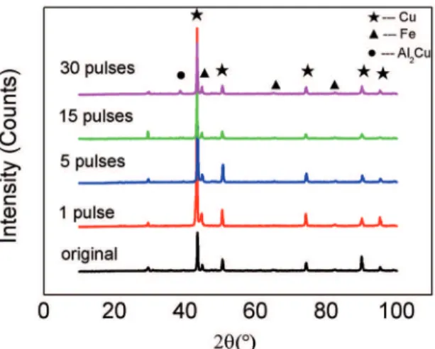
3.2. XRD analysis
XRD measurements were carried out for the aluminized Cu-10Fe alloys before and after HCPEB treatments and results are shown in Figure 3. One can notice that Cu and
α-Fe phases are always the majority in the surface layers
of all samples. Nevertheless, a new phase of Al2Cu is
deinitely detected in those HCPEB-treated samples. This
is consistent with the microstructural analysis according to Figure 2.
Figure 1: (a) surface SEM micrograph of the Cu-10Fe master alloy (the gray and the light indicate Fe-rich phases and Cu-rich substrate,
Figure 2: Micrographs and EDS results (red, green and blue lines indicate Cu, Fe and Al, respectively) illustrating microstructures of
Cu-10Fe alloys with diferent pulses: (a) and (b) 1 pulse; (c), (d)
and (e) 5 pulses; (f) 15 pulses; (g) and (h) 30 pulses
Figure 3: XRD patterns of the aluminized Cu-10Fe alloys with and without HCPEB irradiation
3.3. Microhardness and coeicient of friction
Microhardness variation from surface layers to substrates
and coeicients of friction (COFs) all samples are measured
and presented in Figure 4. From Figure 4a, one can see that for the unirradiated sample, the top surface appears to be
the softest, followed by an almost constant hardness value towards the substrate. This is because that the top surface
is composed of relatively soft Al ilms, compared with
the harder substrate. After HCPEB treatments, however,
signiicant hardness increase can be noticed for the top
surface of samples; the prior softest part becomes the hardest even for the sample with a single shot. With increasing pulse numbers, a general increase trend is seen for the top surfaces of the irradiated samples. For the 30-pulse treated sample, highest hardness value (256 HV) is obtained in the current
work, which is 45% higher than the as-sputtered Al ilm.
Figure 4b presents the surface COFs measured for all samples. For the unirradiated sample, the COF is about 0.5. After one-pulse treatment, the COF rapidly increases to higher than 0.6. As the pulse number increases, a clear decrease trend can be seen, with the lowest COFs value of about 0.3 achieved for the 30-pulse treated sample.
3.4. Corrosion resistance
The polarization curves and corrosion current densities are displayed in Figure 5 and Table 1 to reveal the change of corrosion resistance between the initial and irradiated samples. According to the Tafel extrapolation, corrosion current density (Icorr), corrosion potential (Ecorr) and corrosion rate are acquired and given in Table 1. From both Figure 5 and Table 1, one can see after the HCPEB irradiation, Ecorr and Icorr of all samples with various pulse numbers are respectively higher and lower than the unirradiated sample. For the most heavily irradiated sample (30 pulses), the highest Ecorr and the lowest Icorr are obtained. Generally, a lower corrosion current density indicates a slower corrosion rate. This is also the case in the present work, as revealed in
Table 1. Therefore, the corrosion resistance can be efectively
improved by the HCPEB treatment. The sample irradiated for 30 pulses presents the best corrosion resistance, corrosion rate of which is 6 times slower than the initial sample.
4. Discussion
Due to the high accelerating voltage (25 keV) and high energy density of the HCPEB treatments employed in this
work, the surface of Cu-10Fe alloys with Al ilms could be
remelted rapidly and produce splashing phenomenon. Even for sample with only one pulse, craters with various sizes are formed as shown in Figure 2a. With further irradiation, as seen from the surface morphology after 5-pulse irradiation (Figure
2c), a great mass of Al ilms melt with craters and cracks
appearing (Figs. 2d and 2e). As the pulse number increases,
the phenomenon of remelting and rapid solidiication would
continue near the surface of the Cu-10Fe alloy. According to binary Cu-Fe phase diagram, metastable liquid phase separation
could appear during the process of rapid solidiication. The
Figure 4: (a) Microhardness and (b) coeicient of friction of the aluminized Cu-10Fe alloys with and without HCPEB irradiation
Figure 5: (a) polarization curves and (b) corrosion current density of the aluminized Cu-10Fe alloys with and without HCPEB irradiation
Table 1: Corrosion data of the aluminized Cu-10Fe alloys with and without HCPEB irradiation.
sample Ecorr /mV Icorr /(μA/cm2) Corrosion Rate(mm/a)
initial -613.1 290.75 8.60
1 pulse -452.5 126.58 6.52
5 pulses -602.9 113.13 5.83
15 pulses -475.4 51.22 2.64
30 pulses -419.0 27.23 1.43
when the pulse number increases to 30 (Figure 2g). From EDS and XRD analyses, the new Al2Cu phases are formed on the alloy surface. The formation of the Al2Cu intermetallic
compounds is believed to relate to large diferences of atomic
radii and electro-negativity between Cu and Al. As the Al2Cu compound owns high melting point and hardness, they can make major contribution to improve the surface strength, hardness, wear resistance and heat resistance.
The cross-section microhardness proile presents a
downtrend from the top surface to the alloy substrate (Figure 4(a)), primarily due to considerable energy loss in the process
of high energy particle efect gradually difused to the substrate
by HCPEB irradiation26. The force is gradually decreased
from the surface to the substrate in the heat-afected zone formed in the range of 200μm.
A slight COF increase of the alloy surface after one-pulse irradiation (Figure 4(b)) may be attributed to the formation of coarse craters. Subsequently, it decreases rapidly with
increasing pulse number. Actually, the inal hardness of specimens is afected mainly by the following two factors:
the surface alloying which leads to the formation of the Al2Cu phase and the ine grain structure induced by the rapid
solidiication of the melted layer. The formation of Fe-rich
spheres due to liquid phase separation during the process of HCPEB treatments is another reason for the increased surface microhardness.
The improvement of corrosion resistance can be attributed in part to the generation of Cu2O by oxidation-reduction reaction in 3.5 wt.% NaCl solution27. The occurrence of
greatly improve its microstructure reinement and inhibit localized corrosion. Meanwhile, rapid solidiication increases
the solubility of alloys, dissolving the elements into the matrix. This reduces the generation of harmful precipitates and leads to better corrosion resistance. Generation of supersaturated solid solution after metastable liquid phase separation may be another reason for improved corrosion resistance. In addition,
the liquid phase separation-induced ine spheroids were
reported28 to be able to disrupt continuity of passive ilms
during corrosion, thus should also contribute to improved corrosion resistance in HCPEB-treated specimens.
5. Conclusions
Surface microstructure and corrosion resistance of an aluminized Cu-10Fe alloy after HCPEB treatments were investigated. Results show that typical craters could be induced by HCPEB treatments in Cu-10Fe alloy. The microstructure,
microhardness, coeicient of friction and phase constitution could be remarkably modiied by the HCPEB treatments.
The surface microhardness can be increased by more than
45%, due to combined efects of the ine grain structure induced by the rapid solidiication of the melted layer, the
occurrence of Al2Cu phase and liquid phase separation. These
factors also signiicantly improve the corrosion resistance of
Cu-10Fe alloy, with the best corrosion resistance obtained in the 30-pulsed sample.
6. Acknowledgments
This study is inancially supported by the National
Natural Science Foundation of China (51101177, 51401040, 51401039, 51171146 and 51171216) and the Natural Science Foundation of Chongqing (CSTC2015ZDCY-ZTZX0201, CSTC2012JJA245 and CSTC2013JCYJA50016). China Postdoctoral Science Foundation (2015M572446), Postdoctoral Science Foundation of Chongqing (Xm2015003), and
Scientiic and Technological Research Program of Chongqing
Municipal Education Commission (KJ1500901).
7. References
1. Mei XX, Fu JQ, Li XN, Sun WF, Dong C, Wang YN. Surface
nanostructure of a directionally solidiied Ni-based superalloy
DZ4 induced by high intensity pulsed ion beam irradiation.
Applied Surface Science. 2012;258(20):8061-8064.
2. Zou J, Zhang K, Grosdidier T, Dong C. Analysis of the evaporation and re-condensation processes induced by pulsed beam treatments. International Journal of Heat and Mass Transfer. 2013;64:1172-1182.
3. Mei XX, Liu X, Wang C, Wang Y, Dong C. Improving oxidation resistance and thermal insulation of thermal barrier coatings by intense pulsed electron beam irradiation. Applied Surface
Science. 2012;263:810-815.
4. Proskurovsky DI, Rotshtein VP, Ozur GE, Ivanov YF, Markov AB. Physical foundations for surface treatment of materials with low energy, high current electron beams. Surface and
Coatings Technology. 2000;125(1):49-56.
5. Zou JX, Zhang KM, Grosdidier T, Dong C, Qin Y, Hao SZ, et al. Orientation-dependent deformation on 316L stainless steel induced by high-current pulsed electron beam irradiation.
Materials Science and Engineering: A. 2008;483-484:302-305.
6. Zhang KM, Zou JX, Bolle B, Grosdidier T. Evolution of residual stress states in surface layers of an AISI D2 steel treated by low energy high current pulsed electron beam. Vacuum. 2013;87:60-68.
7. Samih Y, Marcos G, Stein N, Allain N, Fleury E, Dong C, et
al. Microstructure modiications and associated hardness and
corrosion improvements in the AISI 420 martensitic stainless steel treated by high current pulsed electron beam (HCPEB).
Surface and Coatings Technology. 2014;259(Pt C):737-745.
8. Hao S, Gao B, Wu A, Zou J, Qin Y, Dong C, et al. Surface
modiication of steels and magnesium alloy by high current
pulsed electron beam. Nuclear Instruments and Methods in
Physics Research Section B: Beam Interactions with Materials and Atoms. 2005;240(3):646-652.
9. Gao B, Hao S, Zou J, Wu W, Tu G, Dong C. Efect of high current
pulsed electron beam treatment on surface microstructure and wear and corrosion resistance of an AZ91HP magnesium alloy.
Surface and Coatings Technology. 2007;201(14):6297-6303.
10. Hao Y, Gao B, Tu GF, Li SW, Hao SZ, Dong C. Surface
modiication of Al–20Si alloy by high current pulsed electron
beam. Applied Surface Science. 2011;257(9):3913-3919.
11. Hao Y, Gao B, Tu GF, Cao H, Hao SZ, Dong C. Surface
modiication of Al–12.6Si alloy by high current pulsed electron
beam. Applied Surface Science. 2012;258(6):2052-2056.
12. He J, Zhao JZ, Ratke L. Solidiication microstructure and
dynamics of metastable phase transformation in undercooled
liquid Cu–Fe alloys. Acta Materialia. 2006;54(7):1749-1757.
13. Dai J, Yin Z, Zhang J. Efects of thermomechanical treatment
on microstructure and properties of Cu-0.1wt%Fe-0.03wt%P alloy. Heat Treatment of Metals. 2008;33(2):64-68.
14. Zhang Y, Gao J, Yasuda H, Kolbe M, Wilde G. Particle size distribution and composition in phase-separated Cu75Co25 alloys
under various magnetic ields. Scripta Materialia. 2014;82:5-8.
15. Zhang Y, Simon C, Volkmann T, Kolbe M, Herlach D, Wilde G. Nucleation transitions in undercooled Cu70Co30 immiscible alloy. Applied Physics Letters. 2014;105(4):041908.
16. Hong SI, Song JS, Kim HS. Thermo-mechanical processing and
properties of Cu–9Fe–1.2Co microcomposite wires. Scripta Materialia. 2001;45(11):1295-1300.
17. Maggio RD, Ischia G, Bortolotti GM, Rossi F, Molinari A. The
microstructure and mechanical properties of Fe–Cu materials
fabricated by pressure-less-shaping of nanocrystalline powders.
Journal of Materials Science. 2007;42(22):9284-9292.
18. Chai LJ, Zhou ZM, Xiao ZP, Tu J, Wang YP, Huang WJ. Evolution of surface microstructure of Cu-50Cr alloy treated by high current pulsed electron beam. Science China Technological
19. Gao Y. Surface modiication of TC4 titanium alloy by high current pulsed electron beam (HCPEB) with diferent pulsed energy
densities. Journal of Alloys and Compounds. 2013;572:180-185.
20. Cai J, Yang SZ, Ji L, Guan QL, Wang ZP, Han ZY. Surface microstructure and high temperature oxidation resistance of thermal sprayed CoCrAlY coating irradiated by high current pulsed electron beam. Surface and Coatings Technology. 2014;251:217-225.
21. Wang Y, Li Z, Du J, Wang B. Mechanical properties of the
plasma-enhanced magnetron sputtering Si–C–N coatings. Applied Surface Science. 2010;257(1):1-5.
22. Dong C, Wu A, Hao S, Zou J, Liu Z, Zhong P, et al. Surface treatment by high current pulsed electron beam. Surface and
Coatings Technology. 2003;163:620-624.
23. Rotshtein VP, Ivanov YF, Proskurovsky DI, Karlik KV, Shulepov IA, Markov AB. Microstructure of the near-surface layers of austenitic stainless steels irradiated with a low-energy, high-current electron beam. Surface and Coatings Technology. 2004;180:382-386.
24. Hao S, Zhang XD, Mei X, Grosdidier T, Dong C. Surface
treatment of DZ4 directionally solidiied nickel-based superalloy
by high current pulsed electron beam. Materials Letters. 2008;62(3):414-417.
25. Ivanov Y, Matz W, Rotshtein V, Günzel R, Shevchenko N. Pulsed electron-beam melting of high-speed steel: structural phase transformations and wear resistance. Surface and Coatings
Technology. 2002;150(2-3):188-198.
26. Hao SZ, Wu PS, Zhang XD, Zou JX, Qin Y, Dong C. Surface
modiication by high current pulsed electron beam. Heat Treatment of Metals. 2008;33(1):77-81.
27. El-Egamy SS. Corrosion and corrosion inhibition of Cu–20%Fe
alloy in sodium chloride solution. Corrosion Science. 2008;50(4):928-937.