The proper filling confirmation of the cavities in massive concrete
structures of nuclear power plants by impact-echo method.
Š. Morávka
a,*
a New Technology Centre in Westbohemian Region, UWB in Pilsen, Univerzitní 22, 306 14 Plzeň, Czech Republic Received 10 September 2007; received in revised form 2 October 2007
Abstract
Nuclear power plants (NPP) are duty to certify their security for renewal of operating license. Security can be significantly affected by defects of ageing concrete reinforced structures. The methods, how to do in-service inspections of these aging structures of NPP more quickly, cheaply and reliably, are still being looking for. Advanced Impact-Echo method seams to be very hopeful. This paper is a part of extensive project and continues a number of papers published in Czech as well as in foreign. It brings a method description and a main results survey of the numerical modeling of the detection of grouted (repaired) voids in massive concrete structures. Cavities are filled by grouting polyurethan compound CarboPur WF. We try to find out if it is possible or impossible to confirm simply, by Impact-Echo method, if cavities have been filled properly. Consequently, these numerical predictions will be verified on real (scaled 1:1) specimens in NRI Řež as a part of this project as well. © 2007 University of West Bohemia. All rights reserved.
Key words: concrete structures, Impact-Echo, diagnostics, wave propagation, numerical simulation, crack, void, cavity.
1. Introduction
Just in-service inspections of reinforced concrete structures having thick section and with not directly accessible areas are included in the first priority group of specific technical issues according the recommendations of OECD-Nuclear Energy Agency, Commission on Safety of Nuclear Installation in the field of ageing management.
Advanced Impact-Echo method (according to ASTM C 1383 - 98a, 1998, see [1]) consists in the locating of void position according to the elastic wave reflections between the void or inhomogeneities and surface. Generally, it is possible to go by two ways. The matter of technique in the first approach (in frequency domain, exactly according to the ASTM) is the fact that the frequency of wave reflections between the void and surface (or between two surfaces) depends on the depth of the void. Knowing the wave propagation velocity and by using the discrete fast Fourier transform we can identify the dominant frequency and hence compute void’s depth (or thickness of the wall).
In the second way (in time domain) the voids can be localized simply by the transient wave reflection from the discontinuities and inhomogeneities, according the amplitude, shape and time arrival of reflected waves. This technique is not so common, but it can give next useful results, e.g. [4] or [28].
It is very difficult, even impossible, to detect surface crack and/or to set its depth and inclination by the first way (in the frequency domain). We, unlike the most authors (e.g. Dr. Schubert’s group in Fraunhoffer Institute, Dresden, [26], [27]), try to detect crack and voids in time domain. There were tested the possibilities of Impact-Echo for the detection and localization of reinforcing rods [12] and [21] and numerical simulations of detection of perpendicular cracks on the both surfaces – accessible as well as inaccessible [13] and [21]. Next, the depth effects of cracks perpendicular to the surface were tested in [14] and [22], [23]. The localization of the closed crack inside the wall was modeled as well, [14], [22], [23]. Many simulation and discussion were done about the oblique cracks detection and trying set its inclination angle and depth [15], [16], [24] and [25]. Localization and setting orientation of the large cavities in different positions were simulated in [17], [18].
As noted above, we generally focus on usage of Impact-Echo method in the time domain mode. But in cases, where the defect has one face (or, at least a part of its surface) parallel to the wall surface, we can identify multiply wave reflections between void and wall surface very well. Therefore we confirmed detection in frequency domain as well. The comparison and good agreement of the both of approaches was shown in [17], [18], [19]
The cavities in the thick concrete can raise form different reasons. E.g. some extraneous body can get into mixture during concreting or concrete can be compacted insufficiently. There exist various techniques of repairing. This paper concerns to repairing (filling) cavities by the grouting polyurethan compound CarboPur WF from Minova International, see technical report [3]. We test, in this paper, if it is possible to find out by Impact-Echo method, whether the injected cavity were perfectly filled by CarboPur WF. This material is mixed from two components before application and, in addition, the compound is being filled into cavities with water addition. The water evokes foaming the compound, which depend on the water amount. Some water can occur into cavity before. Therefore the foaming can be unequal and it is exactly not predictable. So, it is very hard to estimate, if it will be possible by acoustic wave reflection to distinguish between free surface and surface of properly filled cavity.
Three different cases will be compared each other – the specimen without any cavity, with empty cavity and with cavity filled by CarboPur WF. The computations will be consequently verified by real measurement on the specimens in NRI Řež.
2. Numerical models
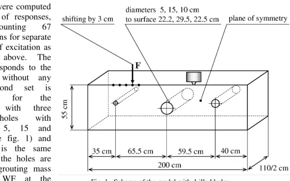
There were computed three sets of responses,
every counting 67
computations for separate positions of excitation as described above. The first set responds to the specimen without any flaw, second set is
computed for the
specimen with three
drilled holes with
diameters 5, 15 and 10 cm (see fig. 1) and third set is the same body, but the holes are filled by grouting mass CarboPur WF at the foaming rate 4.
2.1. Software
Numerical models of Impact-Echo diagnostic method are realized using finite element method implemented in commercial software MARC/MENTAT from MSC Corporation. This software was more times used formerly [12-18], [21-25] and was tested and verified by real experiments and analytical solutions as well, e.g. in [7], [8], [10], [11].
We realized the computations in parallel on META Centre academic network. 14 processors have been used for every task (because we can use 28 MARC licenses).
2.2. Spatial and time discretizations
The concrete walls specimens are 3D bodies modeled by 8-nodes isoparametric elements with full integration. But, the discretization must be finer here to be able to correctly describe relatively small cavities. Therefore the element’s edges have size of 1.5 cm only. It leads to the large models with more than 182,000 elements. These computations are more time extensive than previous ones, e.g. [12-18], because the number of operations responds to third power of the matrix size = approx. number of elements.
From the element size follows, that the shortest wave being able propagates in such model without numerical amplitude attenuation has wavelength
λ
min =30mm. It responds to so called cut-off-frequency at, approximately, 140 kHz. Frequency band of numerical simulation is in the same way restricted by time integration step size as well. Therefore, it is suitable to choose spatial and time discretizations such “rough” or “fine”, that the both frequency limitations will be “similar”. Moreover, we could not use elements of varying size for this type of problems (different cut-off-frequencies and wave dispersions, spurious wave reflections, etc.). These all above facts lead to very extensive and time consuming computations. For more details see e.g. [5], [6], [9], [20].Time integration step with regard to the element size was chosen ∆t=3.5 µs. Time integration consist of 143 steps and it is executed up to time t=500.5 µs, from where the results starts to be devaluated by the wave reflections from the specimen borders.
2.3. Integration method
The Newmark integration method has been chosen for time discretization. The Newmark coefficients were slightly modified from their basic version, to β =0,275625 and γ =0,55. By this way the moderated numerical dumping is introduced. It suppresses spurious higher frequencies namely, but still keeping unconditioned method stability.
The opinions on usage suitability of explicit or implicit formula for transient processes are different. One step computation time by explicit method (e.g. central difference) is smaller, but to reach the same accuracy the shorter time step is needed. It is suitable to choose the time integration method with regards to the spatial discretization type. The spatial discretization with full (consistent) mass matrix used here and time discretization by Newmark method lead to partial elimination spurious effects of the both discretizations, see e.g. [9].
2.4. Materials
Concrete mixture according to technical report about concreting at the NPP Dukovany [2] consists of sand with 4 mm grains and aggregates up to 16 mm sized. It is possible to consider concrete to be homogeneous, because the shortest wavelength
λ
min =30mm is greater. Next, the concrete is made by casting, so it can be considered as isotropic. And last, test loadings are very small, so it will be enough use the elastic model. Mechanical properties respond to the concrete B30 (NPP Dukovany) according to that time standard ČSN 73 12 01.Fill-in mass CarboPur WF from Minova International [3] is synthetic resin based on polyurethan. It is mixed from two components (A, B) and water before application. Due to water presence the mixture froths and final foam expands into all corner of cavity being repaired.
2.5. Excitation
It is realized by impact of experimental hammer. According to impactor size and velocity we estimate impact at force 5,000 N taking time 36 µs. It seems the considerably weaker impact will be enough for real experiments.
3. The results of numerical simulations
We will test, if would is possible to confirm proper fulfillment of a fixed cavity by Impact-Echo. We have computed three sets of tasks – a specimen without any flaw, specimen with three drilled holes and specimen with holes filled by CarboPur WF.
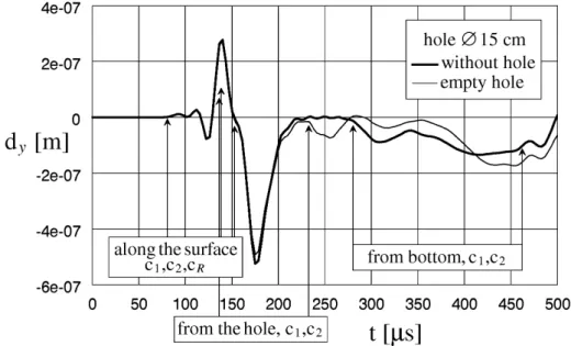
We can find the similar comparison of two curves on the fig. 3. The positions of excitation and sensing are the same, but responses of the specimen with empty holes (thin curve) and specimen with holes filled by CarboPur WF (thick curve) are compared here. It is apparent on the first sight, that the differences are quite neglectable. It doesn’t make possible to distinguish between wave reflections from CarboPur-concrete boundary and reflection from free concrete surface. So-called acoustic impedance (E/ρ ratio) of concrete and CarboPur foam are very different, whilst foam behaves similar to free boundary concrete- air.
Fig. 2. Time histories of displacement perpendicular to surface for full-concrete specimen and for reflection from the central empty hole.
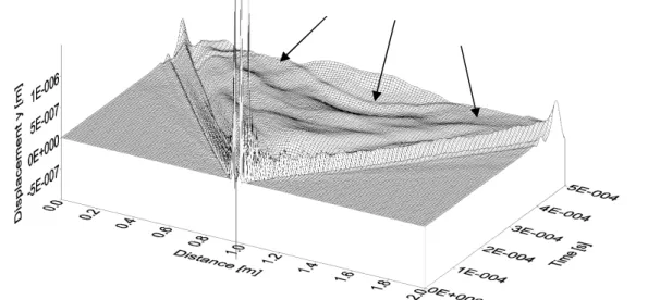
The next two figures (fig. 4 and fig. 5) represent the responses on excitation in the centre of specimen (above the hole diameter 15 cm). The face axis “Distance” is geometrical position from the specimen’s edge. We take time histories of displacement perpendicular to surface from all 134 nodes on this 2 meters line going cross the whole specimen (perpendicularly to the three drilled holes). In such way we can see global response to excitation in one figure. Two triangular areas ahead are divided by dilatation wave front. But it cannot be seen in this scale, because the deflections caused by dilatation wave are small. The outstanding wavefront belongs to the fronts of shear wave and surface Rayleigh wave. Their wavefronts partly coincide each other, as their velocities are similar. The deflected line behind the Rayleigh wave face at the time approx. 270-300 µs belongs to the dilatation wavefront reflection from the specimen’s bottom.
Figure 5 is similar to image to fig.4, but response of specimen with empty holes is depicted here. We can see all the wave fronts as in the fig 4. Only the reflection of dilatation wave from bottom is overlaid by the reflections of shear wavefronts from the holes, see arrows. If we animate this figure moving the excitation position, we could easily distinguish the reflection from every separate hole (will be shown on conference).
It is useless to display here the next figure with responses of specimen with holes filled by CarboPur. It looks nearly exactly like the figure 4 - response of the body with empty holes.
Fig. 4. Responses to the excitation in middle of the specimen taken from all nodes on 2 m line going through the specimen. Specimen without any hole.
4. Conclusion
It is very complicated task for various diagnostic methods to confirm proper filling of the cavities. Ultrasound and georadar don’t succeed as well. Radiography also probably won’t distinguish empty space from CarboPur foam. The Impact-Echo method is very simply applicable and therefore it was suitable to try it on this task as well. But unfortunately it must be submitted, that Impact-Echo method is not able, in practice, distinguish cavity filled by CarboPur foam from empty or partly empty cavity. It is not possible to confirm repairing success and verify proper cavity filling reliably by this way. These numerical predictions will be verified on real (1:1) specimens in NRI Řež.
Just starting work concerns to the cracks caused by the steel reinforcing corrosion. The corrosive products have up to seven time larger volume then pure steel. It results in high pressure and share strain, which can lead up to the concrete damage.
The experimental measurements on real specimens in NRI Řež (scaled 1:1) by various
diagnostic methods are parts of the project as well. There are being (or will be) realized measuring by ultrasound (Inset Liberec and Civil Faculty TU Brno), optically by Moire method (Institute of Thermomechanics Prague), optically by pulse ESPI method (Music Faculty, Academy of Performing Arts Prague), radiography (Civil Faculty of TU Brno) and by Impact-Echo (licensed B&K sensor and originally designed transducer and exciter).
Within the frame of whole project the questions of automated excitation and response scanning are solved, including own devices design.
Acknowledgements
These works are realized in collaboration with Faculty of Civil Engineering of Technical University in Brno in frame of Czech Grant Agency project nr. 103/06/0891 “Testing Methods of Massive Reinforced Concrete Structures” and with Nuclear Research Institute in Řež in frame of research and development program “Impuls”, nr. FI-IM/130,
stage 2.3 “Inspection and Checking of Civil Structures” and are supported by Ministry of Education of Czech Rep. by possibility to use computer clusters of project METACentre, which is realized by CESNET association in frame of research program MSM6383917201
“Optical Net of National Research and its New Applications”.
References
[1] ASTM standard C1383-98a, Standard Test Method for Measuring the P-wave speed and the thickness of Concrete Plates Using the Impact-Echo Method, American Society for Testing and Materials Committee of Standards, PA USA, 1998.
[2] Copy of part of technical report about concreting at NPP Dukovany, chapter IX, Výroba čerstvé betonové směsi, A – Složení směsi, tab.page 18.
[3] Technical report of grouting mass CarboPur WF, Minova Bohemia s.r.o., www.minova.cz or www.minovainternational.com.
[4] Anish Kumar et al., Structural integrity assessment of the containment structure of a pressurised heavy water nuclear reactor using impact echo technique, NDT&E International 35 (2002), p. 213-220, Elsevier Science, Ltd.
[5] R. Brepta, Modifikace metody konečných prvků pro nestacionární problémy dynamiky, Studie ČSAV č.13, 1982, Academia Praha.
[6] R. Brepta, Vlastnosti modelu rovinného kontinua vytvořeného pravoúhlými nebo rovnostrannými trojúhelníkovými prvky, Stroj.časopis 36 (1985), č.4-5, Bratislava.
[8] Š. Morávka, Porovnání analytického řešení nestacionární rázové napjatosti kontinua s výpočtem pomocí MKP, Strojnícky čas.49 (1998), č.6, str.406-425, Bratislava.
[9] Š. Morávka, Společné posouzení vedlejších účinků časové a prostorové diskretizace při nestacionárním zatížení, Národní konference Inženýrská mechanika ’99 , 1999, str. 391-396, Svratka.
[10]Š. Morávka, The Elastic Wave Propagation over the Shape Transitions of Bodies, International Conference Engineering Mechanics 2000, Svratka, pp. 133-138, Czech Republic.
[11]Š. Morávka, Porovnání numerického modelu šíření elastických vln v tělesech s výsledky měření piezoelektrickým snímačem, Vliv přítomnosti snímače na měření, 38th International Conference EAN 2000, pp. 231-236, Tábor.
[12]Š. Morávka, J. Voldřich, Příspěvek numerické simulace k detekci armování a trhlin v železobetonu, 19. konference s mezinárodní účastí Výpočtová mechanika 2003, Nečtiny.
[13]Š. Morávka, J. Voldřich, Application the “Impact-Echo” Method to the Concrete Structure Diagnostic in NPP, National Conference With International Participation Engineering Mechanics 2004, Svratka, Czech Republic.
[14]Š. Morávka, J. Voldřich, Numerické modelování diagnostiky různě hlubokých trhlin a plochých dutin betonových konstrukcí J.E. metodou „Impact-echo“, Computational Mechanics 2004, 20-th conference
with international participation, Nečtiny, Czech Republic.
[15]Š. Morávka, Numerická simulace diagnostiky ukloněných povrchových trhlin tlustostěnných betonových konstrukcí JE metodou „Impact-Echo“, Computational Mechanics 2005, 21-th conference with international participation, Nečtiny, Czech Republic.
[16]Š. Morávka, Oblique Inclined Surface Voids Of Thick-Walled Concrete Structures of Nuclear Power Plants - Numerical Simulation Of Impact-Echo Diagnostic Method, National Conference With International Participation Engineering Mechanics 2006, Svratka, Czech Republic.
[17]Š. Morávka, Numerická simulace detekce objemných dutin tlustostěnných betonových konstrukcí jaderných elektráren metodou Impact-Echo, Computational Mechanics 2006, 22-nd conference with
international participation, Nečtiny, Czech Republic.
[18]Š. Morávka, Application of the Impact-Echo Diagnostic Method for the Detection of Large Cavities in Thick-Walled Concrete Structures of Nuclear Power Plants, National Conference With International Participation Engineering Mechanics 2007, Svratka, Czech Republic.
[19]Š. Morávka, Numerical Simulation of the Impact-Echo Diagnostic Method for the Detection Voids, Crack and Cavities in Thick-Walled Concrete Structures of NPP, International Topical Meeting VVER 2007, Prague, Czech Republic.
[20]M. Okrouhlík, R. Brepta, Side Effect of Finite Element Method Applied on Stress Wave Propagation in a Thin Elastic Bar, Acta Technica ČSAV, No.4 (1976), Praha.
[21]L. Pečínka, Š. Morávka, J. Voldřich, Mathematical Model of the Propagation of P, S and R-Waves in a Concrete Thick Walls with Rebars and Cracks, CSNI/RILEM Workshop on Use and Performance of Concrete in NPP Fuel Cycle Facilities, Madrid, Spain, 2004.
[22]L. Pečínka, Š. Morávka, J. Voldřich, Lessons Learned From Mathematical Modeling of Detection a Deep Surface Cracks and Internal Voids of Thick Walled Concrete Structures Using Impact-Echo Method, Safety Assurance of Nuclear Power Plants with WWER, The 4th International Conference, Podolsk, Moscow Region, Russia, 2005.
[23]L. Pečínka, Š. Morávka, J. Voldřich, Numerical Simulation of the NPP’s Steel-Concrete Structures Diagnostic by the Impact-Echo Method, 18-th International Conference on Structural Mechanics in Reactor Technology (SMiRT 18) Beijing, China, 2005.
[24]L. Pečínka, Š. Morávka, J. Voldřich, In-service Inspection of Thick Walled Concrete Structures, 31. MPA-seminar and symposium ”Materials & Components Behaviour in Energy & Plant Technology”, Materialprüfunganstalt Universität Sttudgart, Germany, 2005.
[25]L. Pečínka, Š. Morávka, In-service Inspections of Thick-Walled Concrete Structures, Problemy pročnosti, No. 4 (2006), pp. 64-78, Nacionalnaja Akademia Nauk Ukrainy, Institut Problem Pročnosti NAN imeni G.S.Pisarenka, Kiev, Ukrajina. Translation ed.: Strength of Materials, Springer New York, Vol. 38, Number 4 (2006).
[26]F. Schubert, Geometrical Effects on Impact-Echo Testing on Finite Concrete Specimens, Symposium NCT-CE Non-Destructive Testing in Civil Engineering 2003, Berlin, Germany.
[27]F. Schubert, On the accuracy of thickness measurements in impact-echo testing of finite concrete specimens - numerical and experimental results, Ultrasonics 42 (2004), p. 897-901, Elsevier B.V.