407
A STUDY OF THE INSTANTANEOUS CENTERS OF ROTATION IN
SINGULARITIES OF 3-DOF FULLY PARALLEL PLANAR
MANIPULATORS
Soheil Zarkandi
Ayandegan Institute of Higher Education, Tonekabon, Mazandaren, Iran Email: [email protected]
ABSTRACT
Finding singular configurations (singularities) of manipulators is obviously important, because these configurations are the ones where the instantaneous kinematics becomes indeterminate. In this paper, singularities of a three degree-of-freedom (DOF) fully parallel planar manipulator are analyzed with the aid of two Jacobian matrices which are expressed through instantaneous centers of rotation and it will be shown that how these centers are located in each type of singularities.
Keywords: Planar Parallel Manipulator, Singularity analysis, Instantaneous centers of rotation, Jacobian matrices
1. INTRODUCTION
Parallel Manipulators consist of multiple branches acting on a common payload platform. These manipulators have various advantages over serial robots, such as high payload to weight ratio, high accuracy, and high rigidity. However, near singular configurations, all the manipulators experience poor performances and parallel manipulators do not exempt from this rule, so these configurations must be found and avoid during design and operation steps. A parallel manipulator finds itself at a singularity when the manipulator either loses or gains one or more degrees of freedom. In contrast to serial mechanism, achieving the singular configurations in parallel mechanisms is so difficult and several authors address these problems with different approach [1-17]. Most of the approaches in singularity analysis used analytical techniques in linear algebra [1-4]. Gosselin and Angeles [1] formulated the instantaneous kinematics using two Jacobian matrices; in this way, they defined three types of singularities according to the rank deficiency of each matrix. Daniali et al. [2] presented a generalized approach to determine the singular configurations of three-DOF planar parallel manipulators that have arbitrary chains and equal number of inputs and outputs. They used a velocity equation including the velocities of active and passive joints in order to determine singular configurations.
Some scholars have also studied singularities by the use of the force transformation matrix; see for instance [5]. These methods allow determining mathematically the singular loci and have found applications in optimization problems.
Another way to deal with the problem of singularity is by using geometrical methods [6-10]. Merlet has obtained singular configurations of parallel mechanisms using Grassmann geometry [6,7]. Bonev et al. [10] found singular configurations of planar parallel manipulators based on the concept of Screw Theory.
Singularity of planar mechanisms can be also studied by exploiting the properties of instantaneous center of rotation (or instant center, in short). The use of instant centers is especially appealing for the analysis of single-DOF mechanisms [11-14], because in these mechanisms their locations depend only on the mechanism configuration [15]. Nevertheless, some papers [16,17] addressed the singularity analysis of multi-DOF planar mechanisms by
using the instant centers’ properties. Raffaele Di Gregorio [13,17] systematically analyses the singularities occurring in planar mechanisms based on the input–output instantaneous relationships; In particular, by classifying the mechanisms based on rotational or translational type of inputs and outputs and by exploiting the properties of the instant centers.
In the present study, singularities of a 3-DOF fully parallel planar manipulator are reviewed using the instantaneous center of rotations between links. This classification is based on the singularities of two Jacobian matrices that relate the input rates to the Cartesian speeds.
2. INSTANTANEOUS CENTER OF ROTATION
408 2.1. The Aronhold-Kennedy Theorem:
Three relative instant centers of the three moving rigid bodies lie on the same line.
There are three types of planar motion between two rigid bodies, namely, translation, rotation and general motion. In translation, the relative velocity of all points are parallel, thus, the ICR lie on a line perpendicular to the velocity vector at infinity. In rotation, the ICR is trivial, while, any generally relative motion can be regarded as a pure rotation about ICR.
3. JACOBIAN MATRICES
In planar parallel mechanisms, the relationship between actuator coordinates, grouped in the 3-dimensional vector , and Cartesian coordinates, grouped in the 3- dimensional vector X, can be written in general as [2]:
s
0
X
θ
,
)
(
f
(1)where f is a 3-dimensional function of
θ
and X, and 0 is the 3-dimensional zero vector. The underlying differential kinematics relations, in turn, take on the form0
Kt
θ
J
(2)where J and K are 33 Jacobian Matrices. Moreover, t is the 3-dimensional twist or Cartesian-velocity vector, and
θ
is the 3-dimensional joint-velocity vector, defined below as:
f
J
,x
f
K
,
C
X
t
,
3 2 1
θ
(3)Furthermore,
is the scalar angular velocity andC
is the 2-dimensional velocity vector of a point of the end-effector (EE), respectively. Below we derive expressions of J and K for a novel 3-RRP planar parallel manipulator where R, P and R denote the revolute joint, prismatic joint and the revolute actuated joint, respectively.The proposed manipulator and its evident instantaneous centers of rotation are shown in Fig. 1a and Fig. 1b, respectively. Three motors M1, M2 and M3 are fixed to the base.
The velocity of a point "C" of the end-effector can be written for the i-th leg, as shown in Fig. 1a, as
)
(
AiAi
C
v
v
C
(4)where vAi and
C
are the velocity of joint Ai and the point "C", respectively. The velocity of instant center Cmn,considered as a point of link q and evaluated in a reference system fixed to link r, will be denoted as r
v
mnq.We can prove that:
)
(
mn qrqr q
mn r
C
C
E
v
(5)while ωqr is the relative angular velocity between links q and r; E is a 2
2 orthogonal matrix rotating vectors in a409
A4
A
6M
1M2
M3
A2
C
(a)
C
45C
67C12
C
14C16
2
4
5
7
6
C
233
C
8
b
4b
2b
6(b)
6
4
2Figure 1. (a) a 3-DOF 3-RRP planar parallel manipulator, (b) the evident instantaneous center of rotations of the manipulator
0
1
1
0
E
(6)Considering Eq. (5) together with Fig. 1b, we can write each term of Eq. (4) as
)
(
ij 1ii
Ai
E
C
C
v
(7a)i i ij
Ai
E
C
C
b
v
C
)
(
)
(
,i
2
,
4
,
6
andj
i
1
(7b)with
i denoting the rate of the prismatic joint and unit vector bi represents the direction of this joint. Substitutionof the values of vAi and
(
C
v
Ai)
from relations above into Eq. (4) yields:0
C
C
C
E
b
C
C
E
i(
ij
1i)
i i
(
ij)
,i
2
,
4
,
6
andj
i
1
(8) Since
i is associated with an unactuated joint, it should be eliminated, which can be done by multiplication of theabove equation by
b
iTE
. Doing this multiplication fori
2
,
4
,
6
leads to:0
C
E
b
C
C
b
C
C
b
T i ij T i i ij T ii
(
1)
(
)
,i
2
,
4
,
6
andj
i
1
(9)Upon writing Eq. (9) for i = 2,4,6, we obtain the following relation.
0
Kt
θ
J
(10)in which 3 3 16 67 6 14 45 4 12 23 2
)
(
0
0
0
)
(
0
0
0
)
(
C
C
b
C
C
b
C
C
b
J
T T T (11a) 3 3 6 67 6 4 45 4 2 23 2)
(
)
(
)
(
E
b
C
C
b
E
b
C
C
b
E
b
C
C
b
K
T T T T T T (11b)410
In this section, singularities of the proposed manipulator are analyzed using the method presented by Daniali et al [2]. In parallel manipulators, singularities occur whenever J, K or both become singular. Thus, for these manipulators, a distinction can be made between three types of singularities, which have different kinematics interpretations, namely,
4.1. Inverse kinematic singularities
This type of singularities consists of the set of points where different branches of the inverse kinematics problem meet. This type of singularity occurs when J becomes singular but K is invertible, i.e., when
det(J) = 0 and det(K) 0
Considering matrix J presented above and putting its determinant equal to zero yields:
0
)
(
ij
1i
T
i
C
C
b
,i
2
or 4 or 6 andj
i
1
(12)So the first type of singularities occurs when vectors bi and
(
C
ij
C
1i)
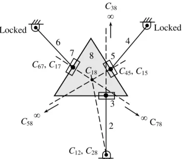
are perpendicular to each other i.e. when atleast the first link of one leg is perpendicular to the direction of the correspondent prismatic joint. In this case, one actuator does not produce any motion of the EE. Thus, the EE cannot move in the direction of the first link of the leg and the manipulator loses at least one degree of freedom.
C45, C15
C78
2
5
4
6
8
C12, C28
3
Locked
Locked
C18
C67, C17
∞
C
58∞
C
38∞
7
Figure 2. An example of the first type of singularities of the 3-RRP manipulator in which one leg is at the singular pose and actuators of the other legs are locked.
In this case, if we lock all actuators but the one correspondent to the leg which is at the singular pose then, according to the Aronhold-Kennedy theorem, Ci8 coincides with C1i in which i indicates the first link of the mentioned leg.
This is a criterion that can be used to find configurations corresponding to this type of singularities. Fig. 2 shows the manipulator at this type of singularity in which one leg is at the singular pose and actuators of the other legs are locked.
4.2. Direct kinematic singularities
This type of singularities, occurring only in closed kinematics chains, arises when K becomes singular but J is invertible, i.e., when
det(J)
0
and det(K) = 0411
This type of configuration can be inferred from Eq. (11b) by imposing the linear dependence of the columns or the rows of K. By inspection of Eq. (11b), two different cases for which we have this type of singularity can be identified.
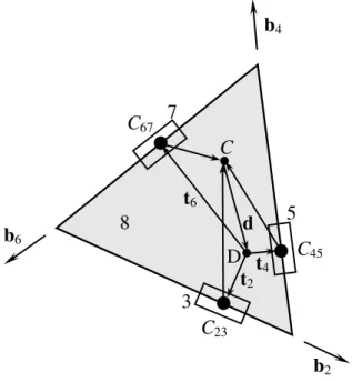
The first case in which K is singular occurs when rows of K are linearly dependent. i.e. when we can write the each row of K as a linear combination of two other rows. This case of singularity occurs when the three vectors ti through
point Cij and perpendicular to bi intersect at a common point. Let us call the intersection point as D, as shown in Fig.
3.
C
23C
67C
45C
D
3
7
5
8
d
t
4t
6t
2b
2b
6b
4Figure 3. Intersection of three vectors ti at a point in the second type of singularity
.
Since the three vectors bi (i=2,4,6) are coplanar, we can express b6 as a linear combination of the first two, namely,
4 2 2 1
6
b
b
b
(13)The inner product of Eq.(13) by vector d leads to
d
b
d
b
d
b
6T
1 2T
2 4T (14)where
d
CD
. But we have:0
i T i
t
b
,i
2
,
4
,
6
(15)So, Eq. (14) can be written as:
)
(
)
(
)
(
6 1 2 2 2 4 46
d
t
b
d
t
b
d
t
b
T
T
T
(16)Moreover, we have
)
(
)
(
d
t
i
C
C
ij ,i
2
,
4
,
6
andj
i
1
(17)Substituting the values of
(
d
t
i)
, for i = 2,4,6, from the foregoing equation into Eq. (16), yields)
(
)
(
)
(
67 1 2 23 2 4 456
C
C
b
C
C
b
C
C
b
T
T
T
(18)From Eqs. (13) and (18), it is obvious that we can write the third row of K as a linear combination of the first two rows, hence proof is demonstrated.
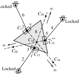
Then, the null space of K represents the set of pure rotations of end-effector about the common intersection point. According to the Aronhold-Kennedy theorem, in this case end effectorcan rotate about C18 while all actuators are
locked. Likewise, a moment applied to end-effector cannot be balanced by the actuators. Thus, the manipulator gains one rotational degree of freedom. Fig. 4 shows the manipulator at this type of singularity while all actuators are locked.
The second case in which K is singular occurs when the three vectors bi are parallel. Therefore, the second and third
412
infinity and the EE can rotates about that point relative to the base while all actuators are locked. However, for the manipulator under study this type of singularity does not occur, because of its architecture.
C
15C
172
4
5
7
6
C13
3
8
Locked
Locked
Locked
C18
C58
C
78C
38
Figure 4. An example of the second type of singularities in which end-effector can rotate freely about
C
18 while all actuators are locked.4.3. Combined singularities
The third type of singularities occurs when both J and K are simultaneously singular, while none of the rows of K vanishes. At these configurations the motion of at least one actuator does not produce any motion of the EE. Therefore, the manipulator loses one or more DOF. As well, the EE can move freely in one or more directions even if all the actuators are locked and some forces or torque applied to it cannot be balanced by the actuators. Thus, the manipulator gains one or more uncontrollable DOFs. Fig. 5 shows such a configuration of the manipulator while all actuators are locked.
C15
C17
2
4
5
7
6
C
133
8
Locked
Locked
Locked
C
18C58
C78
C38
413 5. CONCLUSIONS
The Jacobian matrices of a 3-DOF fully parallel planar manipulator, ruling on the kinematic behavior of the manipulator, are obtained on the basis of instantaneous centers of rotation. The three types of singularities, which have different kinematics interpretations were identified for the manipulator and investigated through the instant centers. The simplicity and the robustness of the method make it possible to implement it for all planar parallel manipulators.
6. REFERENCES
[1]. C.M. Gosselin, J. Angeles, Singularity analysis of closed-loop kinematic chains, IEEE Trans. Robot. Automat. 6 (3), 281–290 (1990).
[2]. H. R. Mohammadi Daniali, P. J. Zsombor-Murray, J. Angeles, Singularity Analysis of Planar Parallel Manipulators, Mechanism and Machine Theory 30(5), 665-678 (1995).
[3]. X.-J. Liu, J. Wang, G. Pritschow, Kinematics, singularity and workspace of planar 5R symmetrical parallel mechanisms. Mech. Mach. Theory 41(2), 145–169 (2006).
[4]. Y. Li, Q. Xu (2007). Kinematic analysis of a 3-PRS parallel manipulator, Robotics and Computer-Integrated Manufacturing 23, 395–408.
[5]. B. Dasgupta, T.S. Mruthyunjaya, Force redundancy in parallel manipulators: theoretical and practical issues. Mech. Mach. Theory 33 (6), 727–742 (1998).
[6]. J. P. Merlet (1991). Singularity configurations of parallel manipulators and Grassman geometry. Int. J. Rob. Res. 10(2), 123–134
[7]. J. P. Merlet, Parallel manipulators, part 2: singular configurations and Grassman geometry. INRIA Report no. 791 (1988).
[8]. J. O’Brien, J. T. Wen, Singularities in three-legged platform-type parallel mechanisms. IEEE Trans. Robot. Autom. 19(4), 720–725 (2003).
[9]. H. Pendar, M. Mahnama, H. Zohoor. A novel method on singularity analysis in parallel manipulators. Submitted to the 8th biennial ASME Conference on Engineering Systems Design and Analysis, ESDA (2006).
[10]. I. A. Bonev, D. Zatlanov, C. M. Gosselin, Singularity analysis of 3-DOF planar parallel mechanisms via screw theory, ASME J. Mech. Des. 125 (3), 573–581 (2003).
[11]. K.H. Hunt. Kinematic Geometry of Mechanisms, Oxford University Press, , ISBN 0-19-856124-5 (1978). [12]. H.-S. Yan, L.-I. Wu, On the dead-center positions of planar linkage mechanisms, ASME J. Mech.,
Transmissions, Autom. Des. 111 (1), 40–46 (1989).
[13]. R. Di Gregorio, A novel geometric and analytic technique for the singularity analysis of one-DOF planar mechanisms, Mech. Machine Theory 42 1462–1483 (2007).
[14]. G.R. Pennock, G.M. Kamthe, Study of dead-centre positions of single-degree-of-freedom planar linkages using Assur kinematic chains, in: Proc. IMechE, Part C, J. Mech. Eng. Sci. 220, 1057–1074 (2006).
[15]. R. Di Gregorio. An algorithm for analytically calculating the positions of the secondary instant centers of indeterminate linkages, ASME J. Mech. Des. 130 (4) (2008).
[16]. D. Sen, T.S. Mruthyunjaya, A centro-based characterization of singularities in the workspace of planar closed-loop manipulators, Mech. Machine Theory 33 (8), 1091–1104 (1998).