UNIVERSIDADE FEDERAL DO RIO GRANDE DO NORTE
–
UFRN
CENTRO DE CIÊNCIAS EXATAS E DA TERRA - CCET
PROGRAMA DE PÓS-GRADUAÇÃO EM CIÊNCIA E
ENGENHARIA DE MATERIAIS
TESE DE DOUTORADO
PROCESSING OF HIGHLY POROUS TITANIUM PARTS BY METAL INJECTION
MOULDING IN COMBINATION WITH INNOVATIVE PLASMA TREATMENT
NATÁLIA DE FREITAS DAUDT
Orientador: Prof. Dr. Clodomiro Alves Junior
Co-orientadora: Prof. Dra. Ana Paula Cysne Barbosa
Tese nº ___/PPGCEM
Natália de Freitas Daudt
Processing of highly porous titanium parts by Metal Injection Moulding in combination with innovative Plasma Treatment
Tese apresentada ao Programa de Pós-Graduação em Ciência e Engenharia de Materiais na Universidade Federal do Rio Grande do Norte, como parte dos requisitos para obtenção do título de Doutor em Ciência e Engenharia de Materiais.
Área de Concentração: Materiais Metálicos
Orientador: Prof. Dr. Clodomiro Alves Júnior Co-orientadora: Prof. Dra. Ana Paula Cysne Barbosa Orientador no Forschungszentrum Jülich: P.D. Dr. Martin Bram
Natália de Freitas Daudt
Processing of highly porous titanium parts by Metal Injection Moulding in combination with innovative Plasma Treatment
Esta tese foi julgada adequada à obtenção do título de Doutor em Ciências e Engenharia de Materiais e aprovada em sua forma final pelo Curso de Doutorado em Ciências e Engenharia de Materiais da Universidade Federal do Rio Grande do Norte.
Natal, 03 de Março de 2015.
______________________________________________________ Prof. Dr. Clodomiro Alves Júnior
Universidade Federal Rural do Semi-Árido
______________________________________________________ PD. Dr. Martin Bram
Forschungszentrum Jülich
______________________________________________________ Prof.ª Dra. Marize Varella de Oliveira
Instituto Nacional de Tecnologia
______________________________________________________ Prof.ª Dra. Ana Paula Cysne Barbosa
Universidade Federal do Rio Grande do Norte
______________________________________________________ Prof. Dr. Uilame Umbelino Gomes
Acknowledgments
This PhD thesis was written during my work as PhD student of the Postgraduate Program in Materials Science and Engineering (PPGCEM) at the Universidade Federal do Rio Grande do Norte (UFRN) from March 2012 to March 2015. The experimental part was conducted during my internship at the Institut für Energie und Klimaforschung (IEK-1) at the Forschungszentrum Jülich from February 2013 to November 2014. I thank all professors, colleagues and employees from PPGCEM and IEK-1.
I would like to express my thanks to my advisor Prof Dr Clodomiro Alves Junior for the guidance of my PhD studies. His knowledge about plasma processing and comments contributed for the improvement of this work.
A special acknowledgment to my advisor at the Forschungszentrum Jülich, P.D. Dr Martin Bram for encouraging my research and his support during my time in Jülich. Dr Martin Bram’s comments, suggestions and reviews strongly improved my PhD thesis and were very helpful for my career. I have learnt a lot in Jülich due to his dedication and constructive discussions.
I thank very much Dr Ana Paula Cysne Barbosa for her advices, comments, English corrections and for the assistance with my preparation for the PhD defence. Her dedication and encouragement were very important during my PhD work and for my future career. I also thank her for helping me with my grant.
I sincerely thank Prof Alexander Laptev for the value comments and discussion, which supported my work in Jülich, in special for his contribution (discussions and analyses) in the optimization of space holder removal by sublimation.
Thanks to Dr Hans Peter Buchkremer, former head of IEK-1 and Prof Olivier Guillon current head of IEK-1, who enabled me to carry out the experimental part of my work at the IEK-1 at the
Forschungszentrum Jülich, which played a major role in my qualification and future career.
I would like to thank Prof Dr Rubens Maribondo do Nascimento, head of the PPGCEM, for his assistance with the implementation of my grant.
I thank my committee members: Dr Ana Paula Cysne Barbosa, Prof Dr Clodomiro Alves Junior, Prof Dr Marize Varella de Oliveira, P.D. Dr Martin Bram and Prof Dr Uilame Umbelino Gomes for their comments and suggestions.
The support with the experimental part, especially feedstock preparation and warm compaction provided by Dr Martin Bitzer is highly acknowledged.
my samples, Mr Gerd Mattonet and Mr Fred Oellers for preparing the steel samples, Mrs Sigrid Schwarzt-Lückge for the particle size analysis and Dr Doris Sebold for the SEM analysis.
I thank Mr Jörg Bartsch from IEK-2 for the metallography preparation of the etched Ti samples, Dr Nicole Lühmann from ZEA-3 for the IR and Raman spectroscopy analysis and Mrs Hannelore Lippert from ZEA-3 for the chemical analysis.
I would like to thank my officemates at the IEK-1: Mrs Biyao Wu, Mrs Sonia Rodríguez, Mr Moreno Scrignari, Mr Woobin Jeon, Mr Andreas Franke for the pleasant work atmosphere and cooperation. I also thank Mr Adam Kot and Dr Oleg Tokariev for the nice work atmosphere at the laboratory and suggestions for my work.
I am grateful to Dr Sven Uhlenbruck for the assistance with the preparation for the A1 Deutsch Prüfung.
I acknowledge the colleagues and former colleagues from UFRN: Mrs Duciane Furtado, Dr Júlio Cesar Barbosa, Dr Haroldo Macêdo, Mrs Laura Camila Santos, Dr Marina Macêdo, Mrs Poliana Santos, Mrs Rafaela Santos and Mrs Raquel Carvalho, for the cooperation during the courses and helpful discussions at the Labplasma.
Thanks to my friends: Dr Beatriz Cela Greven for bringing me a little of Brazil in Germany and Mrs Duciane Oliveira de Freitas Furtado for her kind help and reception during my stay in Natal.
A special thanks to my parents, for the wise advices, support, encouragement and for their high effort to enable my education. I am also grateful to my brother and sisters for encouraging me. Last, I thank my nephew, Mateus, and my niece, Clara, the sunshine of my life.
ABSTRACT
Daudt, N. F. Processing of highly porous titanium parts by Metal Injection Moulding in combination with innovative Plasma Treatment. Natal, 2015. Doctorate thesis. 197 p., Materials Science and Engineering Postgraduate Program, Federal University of Rio Grande do Norte.
temperature during the plasma processing of MIM parts. Highly porous titanium parts were analysed regarding the effect of plasma treatment and feedstock composition on the uptake of chemical impurities, dimensional accuracy after processing steps, sintered microstructure, surface and bulk porosity. Plasma treatment increased the amount of open pores at the surface and improved dimensional accuracy of MIM samples. Therefore, plasma treatment of samples produced by MIM with addition of temporary space holder has the potential to be applied as a standard manufacturing process for highly porous samples. Summing up, all investigated routes are promising for production of porous titanium implants by MIM, since they enabled sintering of highly porous parts, with good dimensional accuracy, open porosity at the surface and final porosity in the range suitable for bone ingrowth (ca. 65 Vol.%).
RESUMO
Daudt, N. F. Processamento de amostras de titânio altamente porosas através de moldagem por injeção de pós-metálicos em combinação com tratamento por plasma. Natal, 2015. Tese de doutorado. 197 f., Programa de Pós-Graduação em Ciência e Engenharia dos Materiais, Universidade Federal do Rio Grande do Norte.
amostras injetadas. Uma investigação detalhada foi conduzida com o objetivo de determinar o mecanismo de modificação por plasma das amostras injetadas com agente espaçante. Além disso, ligas de aço bem conhecidas foram tratadas por plasma a fim de avaliar a temperatura durante o tratamento das amostras injetadas. As amostras porosas de titânio foram analisadas com relação ao efeito do tratamento por plasma e da composição do material de trabalho na contaminação por elementos intersticiais, precisão geométrica após cada etapa do processamento, microestrutura, porosidade no volume e na superfície da amostra. O tratamento por plasma aumentou a quantidade de poros abertos na superfície e melhorou a precisão geométrica das amostras. Logo, tratamento por plasma de amostras produzidas por MIM com adição de agente espaçante tem potencial para ser aplicado como processo padrão de produção de amostras altamente porosas. Resumindo, todas as rotas estudadas são promissoras para a produção de implantes de titânio porosos através da MIM, uma vez que permitem a sinterização de titânio altamente poroso com boa precisão geométrica, porosidade aberta na superfície e porosidade final no intervalo adequado para o crescimento ósseo (cerca de 65 Vol.%)
Symbols and Abbreviations
CASING - Cross-linkage by activated species of inert gases CVD - Chemical Vapour Deposition
d - Sample’ diameter dc - Direct Current e- - Electron
Ee - Electrons energy Ei - Ions energy
EVA - Ethylene Vinyl Acetate G - Neutral particle
G* - Excited neutral particle
G+ - Positive charged particle in the ground state h - Sample’s height
H - Hardness
HDH - Hydride-Dehydride
HDPE - High Density Polyethylene HIP - Hot Isostatic Pressing
Jch - Total energy flux of charged particles Je - Total energy flux of electrons
Ji - Total energy flux of ions KCl - Potassium Chloride particles LDPE - Low Density Polyethylene MIM - Metal Injection Moulding msample - Mass of sample
mdry - Mass of dry sample
mi - Mass of sample immersed in water mwet - Mass of sample wet in water OES - Optical Emission Spectroscopy
ρ
- Densityρ
water - Density of waterρ
Ti - Theoretical density of titaniumPEG - Polyethylene glycol PIM - Powder Injection Moulding PM - Powder Metallurgy
POM - Polyoxymethylene PP - Polypropylene
PMMA – Poly-methyl-methacrylate r - Sample’s radius
RF - Radio Frequency SA - Stearic Acid
SHM - Space Holder Method SPS - Spark Plasma Sintering t - Dwell time
T - Temperature
Ts - Titanium powder with spherical particles
UFRN - Universidade Federal do Rio Grande do Norte (Federal University of Rio Grande do Norte) UV - Ultraviolet radiation
VPS - Vacuum Plasma Spraying Vol.% - Percentage by volume wt% - Percentage by weight WC - Warm Compaction
List of Figures
Figure 1. Schematic drawing of blood vessels and tissue ingrowth into the implant structure [27]. ... 31
Figure 2. Commercial spinal implant of the company Synthes. (a) Implants on the vertebrae bone. (b) Row showing the different sizes available. (c) Implant placement after surgery [63]. ... 37
Figure 3. Schematic sketch of PIM technique [64]. ... 38
Figure 4. Three possible situations in a powder-binder mixture: (a) excess of powder, (b) critical and (c) excess of binder [71]. ... 40
Figure 5. Schematic comparison between the traditional MIM process to obtain high dense parts and MIM of feedstock with space holder for production of micro-porous metal [81] ... 45
Figure 6. Spinal implants: (a) Commercial implant obtained by SHM and green machining [63]. (b) Prototype of spinal implant obtained by MIM with temporary space holder (c) and cross section of the prototype obtained by MIM [64]. ... 46
Figure 7. Schematic illustration of mechanism of pore closure in MIM parts with space holder. ... 47
Figure 8. Schematic of 2-C-MIM process combined with the space holder method [64]. ... 48
Figure 9. Typical curve of electrical current versus voltage between two electrodes during dc electrical discharge in gases adapted from Alves Jr. [90]. ... 51
Figure 10. Plasma in abnormal regime. ... 53
Figure 11. Schematic illustration of capacitive RF plasma [108]. ... 55
Figure 12. Schematic illustration of microwave plasma with metal chamber [108]. ... 56
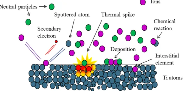
Figure 13. Schematic illustration of the interactions ions-surface on titanium substrate. ... 58
Figure 14. SEM image of bronze sample sintered by hollow cathode discharge [101]. ... 63
Figure 15. Schematic drawing and SEM pictures of inkjet-printed silver tracks on polymer substrates sintered by argon plasma [131]. ... 65
Figure 16. Schematic illustration of plasma interactions with: (a) dense sample and (b) porous sample. ... 67
Figure 17. Model of carbon backbones exposed to post-discharge: interactions with HDPE (adapted from Dufour [147]). ... 69
Figure 18. SEM picture of titanium powder. ... 72
Figure 19. SEM picture of KCl powder... 72
Figure 20. Process diagram for manufacturing WC samples: (a) untreated, (b) plasma-treated after warm compaction, (c) plasma-treated after debinding and (d) plasma-treated after desalination. ... 73
Figure 21. Process diagram for manufacturing MIM samples. ... 74
List of Tables
CONTENTS
27 1 INTRODUCTION
Highly porous titanium has been widely applied as structural and biomedical material because of its excellent mechanical properties, low density, high chemical resistance and biocompatibility [1]. It has been used in impact energy absorbers, sandwich core structure for aerospace or submarine vehicles, lightweight constructions, heat exchanger and catalyst substrate at high temperature [2]. Since the last decade, porous titanium has been awakened growing interest in electrochemical devices, e.g. current collectors [3] and separator plates for water electrolysis and fuel cell [4, 5]. Up to now, biomedical implants are still the most attractive field for porous titanium application due to the above mentioned properties. Additionally, the introduction of well-defined porosity enables manufacturing porous titanium with elastic modulus more similar to that of human bone and pore size suitable to promote bone ingrowth, which reduces the risk of stress shielding and improves the fixation of the implant in the bone [6].
Space Holder Method (SHM) is an established technique employed for the powder-metallurgical manufacturing of net-shaped parts with well-defined porosity, where shaping is based on pressing with subsequent machining in the unsintered state [7]. The adaptation of space holder method to materials with high affinity to oxygen like titanium was conducted at the Forschungszentrum
Jülich. It has been applied for production of biomedical implants such as spinal discs and acetabular
hip prostheses [7, 8]. Usually, mechanical properties, porosity amount and distribution of the implants are defined by the choice of space holder material regarding particle shape, size and amount.
Metal injection moulding (MIM) is a powder metallurgy technique widely used for mass production of small and complex-shaped metal parts. Introduction of space holder particles into MIM feedstocks allows the production of samples with a functional porosity after sintering, which makes this method especially attractive for biomedical implants. Recently, it has been demonstrated that MIM in combination with space holder materials is a promising method to replace the current method (SHM + green machining) for the net-shape manufacturing of titanium implants with well-defined porosities, since it enables a higher degree of automation and reduction of costs in the case of large-scale production [9].
28
deformation and even collapse of samples during thermal debinding and sintering were observed when samples containing more than 55 Vol.% space holder were sintered [9, 10]. However, a space holder content above 65 Vol.%, which results in a final porosity in the range of 60-65 Vol.%, is required in order to achieve a percolating network of macropores, which enables bone ingrowth, while maintaining adequate mechanical properties for bone implants produced by SHM [8, 10]. Therefore, further efforts are necessary to enable the production of porous titanium implants with open porosity at the surface and interconnected macroporosity in the range of 60-65 Vol.% by MIM with addition of space holder particles.
Since more than a decade, plasma treatment is an established technique employed for biomaterials processing, aiming at the improvement of surface properties [11]. The application of plasma-based techniques is quite diverse. It allows the treatment of metallic as well as polymeric materials due to a broad spectrum of operating parameters. In the case of polymeric materials, plasma treatment of low discharge power (80-100 W) and short dwell times (10-300 s) has been performed for instance on polyurethane, polyethylene and polyethylene terephthalate in order to improve blood compatibility [12, 13], roughness, wettability, cell adhesion, spreading and proliferation [14, 15]. Plasma treatments with high discharge power (ca. 500 W) and long dwell time (ca. 3 hours) have been successfully applied to surface modification of titanium implants, where their potential to improve mechanical resistance and biocompatibility have been demonstrated [11].
This PhD thesis was developed in a partnership between the Universidade Federal do Rio
Grande do Norte and the Forschungszentrum Jülich. The experimental part was conducted in Jülich.
The main objective of the present work is the production of highly porous titanium parts with an interconnected bulk porosity and an open porosity at the surface by MIM using temporary space holder. Porous titanium samples combining final porosity in the range of 60-65 Vol.% and open porosity at the surface are expected to be suitable for application as spinal bone implant. Therefore, space holder contents above 60 Vol.% were added to MIM feedstocks. The improvement of shape stability of MIM samples containing temporary space holder during thermal debinding and sintering as well as the removal of the dense layer from the sample surface, aiming to open the porosity at the sample surface, are the challenges of this study.
29 leaching and increase shape stability during sintering. At last, plasma treatment was applied to samples before the final sintering step in order to remove the outer shell, aiming at an open surface porosity.
30
2 LITERATURE REVIEW
2.1 POROUS TITANIUM
Highly porous titanium combines excellent mechanical properties, low density, high chemical resistance and biocompatibility, which makes Ti foams an interesting material for several applications on both structural and biomedical field [1]. The structural applications of titanium-based foams are membranes for filtration [16], impact energy absorbers, sandwich core for aerospace or submarine vehicles and light-weight constructions. They can also be employed at high temperature, such as in heat exchangers and catalyst substrates [2, 17, 18]. Since the last decade, the number of publications on the application of porous titanium parts in electrochemical devices, like current collectors [3, 19] and separator plates for proton exchange membranes used in water electrolysis and fuel cells [4, 5] as well as substrate for electrodes of electrochemical energy storage devices [20] has been a growing steadily. However, up to now, bone implant is the most common and attractive field for applying porous titanium.
Titanium and its alloys are widely used in biomedical applications due to the well-balanced combination of corrosion resistance, mechanical properties (high ratio: mechanical resistance/weight) and biocompatibility [21]. The elastic modulus of titanium and its alloys (55-110 GPa) is more similar to the one of the human bone (4-30 GPa) than the modulus of other metallic implant materials, e.g. stainless steel AISI 316 l (210 GPa) [22], which clearly reduces the risk of stress shielding. Stress shielding is one of the biggest problems of metallic implants, mainly caused by the mismatch of elastic modulus between implant and bone. When elastic modulus of the implant is much higher than the modulus of bone, the implant will receive all loads and the nearby bone will lose density, resulting in displacement of the implant that can make the implant to lose its function [6]. The high affinity of titanium for oxygen is coupled with a spontaneous passivation, leading to the formation of a dense, nano-scaled oxide layer on the surface. This oxide layer is the reason for the high corrosion resistance and outstanding biocompatibility of titanium, which ensures its long-term stability in body fluids [23]. Good biocompatibility is one of the most important properties for a material to be used as
biomedical implant. In the context, ‘‘good biocompatibility’’ refers to a prosthesis or biomaterial
31 and bone tissue, increasing the efficiency of the bone-implant bond [24]. Bone ingrowth into the open surface pores of the implant enables a long-term stable fixation of the implant at the bone-implant interface.
There is an ideal pore size and distribution which promotes bone ingrowth for each type of implant. Bobyn et al. [25] and Fujibayashi et al. [26] reported that the ideal pore size is between 50
and 450 μm. According to Wintermantel and Ha [27], pores bigger than 100 μm allow the growth of cells of conjunctive tissues, e.g. osteoblasts, while pore sizes larger than 450 μm are necessary for blood vessels growth (Figure 1). According to the review published by Karageorgiou and Kaplan [28] pore size should be higher 50 μm, the minimum requirement for pore size is ~ 100 μm due to cell size,
migration and transport and pore sizes ˃ 300μm enhance the new bone formation and the formation of capillaries. Alvarez and Nakajima [29] reported that scaffolds or bone implants should have the most similar possible geometry, size and density to the nearby bone in order to fit in the bone defect, furthermore pore size distribution, porosity, interconnectivity of the scaffold should be enough for cell proliferation, cell migration, matrix deposition, vascularization and mass transport of nutrients. According to Imwinkelried [8], the most suitable range of porosity for spinal implant produced by the space holder method is between 60 and 65 Vol.%, representing the best compromise between mechanical stability and interconnected porosity.
Figure 1. Schematic drawing of blood vessels and tissue ingrowth into the implant structure [27].
32
mechanical stability [8, 30]. Therefore, for some applications (mainly orthopaedic or dental implants), the use of a dense core and a porous coating is more promising. Thus, the reduction of mechanical properties remains at an acceptable level, while there is still a considerable improvement in the interlocking between bone and implant [24].
Today, a couple of commercially-available porous titanium implants are on market, enclosing products like acetabular hip and knee prostheses, modular tibiae tray and shoulder joint replacement as well as spinal implants for replacing the vertebral disc [31, 32]. A major problem for using of titanium is its high cost. One of the ways to get around this problem is by the use of near-net-shape processing such as powder metallurgy (PM). Titanium has a relative high melting point (≈1668 ºC). Nevertheless, PM allows processing titanium at lower temperatures, which facilitates the manufacturing of titanium parts. PM techniques like laser forming, metal injection moulding (MIM), spraying, near-net-shapes (blended elemental and pre-alloyed), metal matrix composites are cost-effective ways for fabricating components from titanium with good dimensional accuracy [33]. On the other hand, the high affinity of titanium for oxygen and other interstitial elements like carbon and nitrogen makes PM processing of titanium and its alloys quite challenging due to the risk of inherent embrittlement if interstitial uptake during processing exceeds a critical value [34].
Titanium powders for PM
Titanium powders normally used in powder metallurgy are roughly divided into pure and expensive powders and comparably unclean and low-cost powders. Purity relates especially to oxygen and carbon content, but also to residuals like chlorides, calcium, sodium or magnesium from the specific production process. These powders differ in geometry as well: the expensive ones are usually more spherical, while the low-cost powders are typical irregularly shaped and often agglomerated.
Current techniques for production of the most expensive powders are inert gas atomization [35] and plasma rotation electrode processing [36]. Low-cost powders are made by mechanical milling of sponge, scrap or ingots, for example as done in the hydride-dehydride process (HDH) [37]. Much research efforts have been dedicated to the direct reduction of titanium oxide without the Kroll process mainly aiming to cut costs of processing. Recently, Mellor et al. [38] demonstrated obtaining titanium powder directly via FFC® Cambridge process from a new technique: titanium metalysis. This new technique is promising for titanium production since it decreases the complexity of Ti production and reduces PM processing steps, thus decreasing processing costs.
33 hydrogen escapes during sintering and reacts with oxygen that possibly exists in the binder, powder and furnace atmosphere. Overall, PM of titanium requires careful consideration of contamination by oxygen, nitrogen and carbon with respect to their strong influence on the mechanical properties [39].
For application in Metal Injection Moulding (MIM), normally, metal powders consisting of spherical particles are required in order to promote good flowability during injection and low uptake of chemical impurities [40].
2.2 METHODS FOR NET-SHAPE MANUFACTURING POROUS TITANIUM
A large number of production routes has been developed, in recent years, aiming at the production of highly porous metal parts for biomedical applications. A short summary of these methods, focused on Ti foams production, is given below. A more detailed description can be found in the literature [1, 29, 39, 41].
1. Selective laser melting (SLM) and electron beam melting (EBM): SLM and EBM of powder beds are rapid prototyping methods, based on computer aided manufacturing (CAM) technologies. Parts with highly complex shapes like porous structures can be produced without any sort of tools or fixtures. Furthermore, the amount of waste material can be reduced to a minimum. For realising complex 3D structures, a metal powder bed is selectively scanned by the spot of a high powered laser or electron beam fusing the metal powder particles by melting. Then further metal powder is applied layer by layer on the powder bed and the selective melting technology is repeated until the 3D computer aided design (CAD) model is realized as a 3D part. Since both processes do not require a binder material, they are suitable for application on oxidation sensitive powders like titanium. There are almost no geometrical limitations, therefore, total porosities above 90 Vol.% and pore sizes in the range of 500 µm up to several mm can be achieved [42, 43, 44].
2. Entrapped gas expansion: The starting powders are encapsulated in a ductile can, which is welded under Argon atmosphere. Afterwards, the powder is compressed to a dense precursor material by hot isostatically pressing (HIP). During compaction, the gas atoms become entrapped by the material. After mechanical removal of the can, heating of the precursor material leads to metal expansion coupled with pore formation due to the internal pressure created by the entrapped gas. The pore formation is based on a solid state creep process [2, 45].
34
Pressure is applied to the foam in order to remove the excess powder slurry. After drying, the template material is decomposed by a thermal treatment at 600 °C, which leads to the formation of triangular pores inside the struts. After sintering, a cellular metallic structure with hollow ligaments is achieved. Usually, net-shaping is done by mechanical machining of the sintered foams. Porosities in the range of 80-95 Vol.% and pore sizes between 300 and 1000 µm were demonstrated recently [46]. This process allows the production of foams with the lowest relative density available.
4. Coating of vitreous carbon foam by chemical vapour deposition (CVD): Open-cell polymer foam can be used as template for deposition of metal coatings by chemical vapour deposition (CVD). Before deposition of the metal, the polymer foam is reduced to vitreous carbon foam by thermal treatment under reducing atmosphere. Then the carbon struts are coated by CVD with a 40-60 µm thick metal layer. Porosities in the range of 75-80 Vol.% and pore sizes in the range of 400-600 µm suitable for implant applications can be achieved [47]. This technique was applied to produce porous tantalum implant like monoblock acetabulum, monoblock tibia, patella buttons, osteonecrosis implants, spine arthrodesis and dental implants [48].
35 2.3 SPACE HOLDER METHOD
Space holder method (SHM) is another established technique employed for the powder-metallurgical manufacturing of net-shaped titanium parts with well-defined porosities and a homogeneous distribution of pores. It allows the production of highly porous parts (porosity up to 80 Vol.%), with pore sizes in the range of 100-700 µm and high dimensional accuracy [7]. The microstructure and mechanical properties of the porous metal can be adjusted by the choice of space holder material regarding shape, size and amount.
The first step of SHM is the selection of the suitable space holder material. The particle size of metal powders should be significantly smaller than the average particle size of space holder powders. The selected metal powder such as titanium powder and the suitable space holder are mixed. In the following step, semi-finished compacts are made by pressing space holder/metal powder mixtures uniaxially or isostatically. The compaction pressure of the mixture must be high enough to provide suitable mechanical resistance for interlocking of adjacent titanium particles, which ensures stability of sample geometry during space holder removal [41]. It is possible to obtain compacted samples with sufficient mechanical stability to be machined in the unsintered state so called “green state”. In principle, machining of highly porous samples parts is also possible in the sintered state, but plastic deformation and smearing of the sintered struts may lead to partial or total closure of surface pores [54]. Therefore, shaping of these compacts is preferentially done by machining in the unsintered state [7]. In the case of small or medium implant dimensions, green machining can be done without any addition of organic binders to powder compacts, minimizing the risk of oxygen and carbon uptake during further processing.
36
adherence, whereas macroporosity (pore diameter in the range of 100 µm up to several mm) provides a scaffold for bone-cell colonisation with vascularisation of blood vessels [31].
Tuncer et al. [55] investigated the pore size effect of space holder on the shape and mechanical properties of porous titanium and concluded that the use of coarser space holder particles results in a thicker pore wall and a wider distribution of pore wall thicknesses. The results indicated that stiffness and strength tend to be improved by increasing pore size. Among the structural features that space holder size, pore wall thickness and pore face roughness were found to be the most dominant effects on strength and stiffness.
The main limitation of SHM is the removal of high amount of space holder from the compacting mixture, which can result in contamination of the final parts and, as a consequence, reduction of mechanical properties. In the case of titanium powders (mainly for biomedical applications), the temperature of space holder removal is also a critical step, since the use of high temperatures can result in increased contamination of the final parts by uptake of interstitial elements like carbon, nitrogen and oxygen. Bram et al. [56] produced porous titanium samples with final porosity between 60 and 80 Vol.% and a pore diameter in the range of 0.1-0.25 mm using carbamide (urea) powder and ammonium hydrogen carbonate as space holder. The use of both carbamide (urea) and ammonium hydrogen carbonate powders as space holder material allowed space holder removal at temperatures below 200 ºC, resulting in a minimum contamination of titanium powders.
Recently, the production of highly porous parts by evaporating NaCl has been reported as a method to increase shape accuracy of highly porous parts obtained by cold pressing [57, 58]. NaCl was used as temporary space holder and evaporated during sintering. Jha et al. [58] produced porous Ti (porosity 65-80 Vol.%) and Yen et al. [57] produced TiNi alloys (porosity up to 90 Vol.%). NaCl has a high vapour pressure; therefore, NaCl could be evaporated during sintering process at low pressure. This unique NaCl evaporation phenomenon facilitated the manufacturing of highly porous materials with porosity greater than 80 Vol.%. In comparison, when the water immersion method is used to extract NaCl, a green compact with over 80 Vol.% porosity does not provide enough strength to retain its geometry since the metal powders are not sintered and the bonding between powders is weak. The leaching step, which is the slowest process step, could be eliminated and the shape retention problem was reduced [58]. Bansiddhi and Dunand [59] produced highly porous Ni-Ti-Nb alloys with porosity of ca. 40 Vol.% by addition of 60 Vol.% space holder (NaCl), which was removed during sintering at 1200 ºC by melting and evaporating. According to Bansiddhi and Dunand [60] there is no chemical interaction between Ti or Ni and Cl during space holder removal by melting and evaporation because the free energy of NaCl formation is much lower than the free energy of TiCl4 or NiCl2 formation.
37 carbonate (NH4)HCO3 as space holder in combination with titanium powder for demonstrating the production of a prototype of acetabular hip prostheses. For net-shape manufacturing, machining of powder-space holder compacts in the unsintered state was introduced.
The adaptation of space holder method for materials with high affinity to uptake of oxygen and carbon was conducted at the Forschungszentrum Jülich. The space holder technique was licensed to the Company Synthes (current DePuySinthes member of Johnson & Johnson Corporation) for the manufacturing of spinal implants with a gradient in porosity [8]. These titanium implants are composed of two parts: one porous and another with a clear reduced porosity, which is required to ensure the implant stability during surgery (Figure 2). The spinal implant is placed in between two vertebrae for replacement of the lumbar disc. The neighbouring bone tissue grows into the implant structure. The structure of porous implant produced by space holder method is advantageous regarding the primary fixation to the bone due to the development of a more homogeneous distribution of bone tissue from the vertebrae into the implant. This bone ingrowth improves the overall mechanical stability of the system. The rotation of the implant during surgery by an angle of 100 º is a specific characteristic of these implants. The rotation promotes a permanent tension of the adjacent vertebrae on the implant, avoiding implant displacement and additionally supports bone ingrowth. For this rotation procedure, sufficient implant strength is required, which is ensured by the dense part of the implant [63].
According to Imwinkelried [8], the best space holder amount for production of the porous portion of spinal implants is in the range of 65-70 Vol.%, since it results in final porosity of titanium implants in the range of 60-65 Vol.%. A porosity in the range 60-65 Vol.% is required to achieve a network of interconnected macropores after sintering, which enables bone ingrowth while maintaining adequate mechanical properties. Lower space holder content results in a limitation of interconnected porosity and causes partially closed surface porosity, while higher space holder content results in poor mechanical properties. Both cases are undesired in implant applications.
38
2.4 METAL INJECTION MOULDING
Powder Injection Moulding (PIM) is a technique derived from conventional plastic injection moulding, which enables production of complex-shaped parts by mixing binder and powder materials. Both metallic and ceramic powders can be injected. Accordingly, injection of metallic powders is named Metal Injection Moulding (MIM) and injection of ceramic powers is called Ceramic Injection Moulding (CIM).
Metal injection moulding was developed in 1970’s. Since then, it has been widely used for the production of small metallic parts with high geometrical complexity, good dimensional accuracy, high productivity and low effective costs. MIM combines the versatility and productivity of polymer injection moulding with properties of metallic materials. Different parts as watches, surgical instruments and automotive pieces can be produced [40]. In order to obtain pieces by PIM, a mixture of binders, which are normally composed of different polymers, and powder materials are used as feedstock. This mixture is moulded, after moulding the binder is extracted and the pieces are sintered. PIM process is schematically shown in Figure 3.
Figure 3. Schematic sketch of PIM technique [64].
39 contact between titanium and atmosphere are necessary [67]. Therefore, recently, the literature reports have been focused on minimizing the entry of interstitial elements into titanium parts [67, 68, 69].
Medical applications are growing from an early base of endoscopic devices, and might become an enormous market as MIM becomes widely accepted. Much of the recent growth has been in minimally invasive surgical tools, production of implants with highly dimensional accuracy and robotic devices. So far only a few MIM companies are positioning for the production of implants and surgical hand tools. Therefore, medical applications are a prime opportunity for MIM [66].
2.4.1 Processing steps of MIM
Feedstock preparation
The first MIM processing step is the feedstock preparation. Metal powder and binder are mixed in an automatic kneader at a temperature above the melting point of the binder components. After mixing and subsequent cooling down, the feedstock is pelleted.
Metal injection moulding is a complex process whose success depends on several factors. The first factor is the choice of starting materials in order to improve the sinterability and to ensure homogenous filling of mould cavity. Preferably, metal particles should be spherical in order to promote flowability during injection [40]. Usually particle sizes below 45 µm are applied. The binder is a temporary vehicle to allow homogeneous powder injection, which should be carefully chosen with respect to the used powder and powder properties.
40
glycol (PEG) and poly-methyl-methacrylate (PMMA) are commonly used as backbone component. In most cases, a third component is added, as a surfactant, which improves compatibility between metallic powders and polymer. In the case of titanium, these requirements are more stringent due to high affinity of titanium to interstitial elements, like oxygen and nitrogen. Consequently, polymers containing nitrogen and oxygen in their chain should be avoided and preferably polymers with low temperatures of decomposition should be used to avoid titanium contamination during binder removal. According to Li et al. [71], generally high powder loading is beneficial to improve the mechanical properties and dimensional accuracy during sintering. However, powder loading cannot be increased unlimitedly. MIM feedstock represents a balanced mixture of powder and binder. There is an optimum amount of binder, which promotes enough lubrication among the particles allowing feedstock injection without problems and minimizing shape distortions during sintering [40].
The amount of binder depends on the powder particle packing, since filling all of the void space among the powder particles is necessary to maintain a low viscosity. There are three possible situations for a powder-binder mixture, as sketched in Figure 4. There is a critical powder loading at which the binder is just sufficient to form a strong, adsorbed layer on all powder particles and to completely fill the inter-particulate voids (Figure 4(b)). It represents the densest packing of powder particles. When the powder loading is higher than the critical one, there is no sufficient binder to fill into the space among powder particles. Therefore, voids are formed inside the feedstock and viscosity becomes very high, deteriorating the feedstock injection (Figure 4 (a)). When the powder loading is lower than the critical value, there is too much binder in the feedstock (Figure 4(c)). Low powder loading results in large volume of shrinkage after sintering, making the tight dimension tolerance control of compacts very difficult. Because the critical powder loading is almost impossible to get in practice, a powder loading just slightly below the critical value is regarded as the optimal powder loading. A feedstock with the optimal powder loading will have good rheological properties for moulding, small distortion and good mechanical properties of the parts after debinding and sintering.
41
Feedstock injection
The second MIM processing step is the feedstock injection into the mould. Firstly, the feedstock is placed into the heated barrel. The feedstock is molten, compressed and injected by hot ramming it under pressure into the mould cavity. The screw placed into the MIM machine promotes the feedstock flow when rotating. The exact amount of mass is separated for the next shot from the reservoir inside the barrel by a metering valve. In the moulding stage, the screw acts as a plunger with a rapid forward motion that forces feedstock flow through the nozzle at hot end of the barrel, as a check ring seals against the screw tip. Then, the feedstock is injected into the mould with the desired shape [40, 72].
The temperature inside the barrel, injection temperature, mould temperature, charging volume, flow rate of the injection volume, injection pressure and holding time can be highlighted as the most important process parameters for feedstock injection. There are four heating zones inside the barrel. These zones can be independently regulated by the computer associated to the MIM machine. The first zone is where the feedstock is quickly molten. In the following zones, the temperature is gradually increased and homogenised inside the barrel. The injection nozzle is the fifth heating zone, where the injection temperature is defined [40, 72].
The position of the screw inside the injection unit defines the charging volume. The forward and backwards movement of the screw enable to inject a well-defined amount of feedstock into the mould. Non-return valve at the front end of the screw avoid the molten feedstock to be pressed back into the barrel. The flow rate of the injection volume is defined by the velocity of the screw displacement, which can be stepwise regulated. When the defined charging volume is achieved, the mass is pressured at the defined holding pressure for a defined time. The rotation of the screw defines the pressure inside the barrel. The holding pressure can also be stepwise regulated, where up to ten subsequent holding pressures with different holding intervals can be defined. The main objective is to compensate the shrinkage of the injected part during cooling down, which is required to avoid crack formation in the green parts [40, 72].
42
First Debinding
During the first debinding step, at least one component of the binder system is removed by melting in a sand bed (wicking) or by solvent extraction. In the case of binder system based on wax, normally the paraffin wax is removed by solvent extraction in n-hexane bath. After wax removal, interconnected pores are formed and the remaining binder (the backbone component) ensures the mechanical stability of samples. The first binder removal step is the main process limitation. Therefore, binder removal is much more time-consuming for large pieces than small pieces.
Thermal debinding and sintering
The last step of MIM process is the removal of the remaining binder and sintering. The remaining binder is removed by a thermal treatment. In the last stage of thermal removal, the binder is present only at the contact points of the particles, and capillary forces keep the particles together until the initiation of sintering [73]. Normally, the sintering is conducted after the thermal removal of the binder in a single step, through increasing the temperature up to the sintering temperature. The usual linear shrinkage during sintering of dense Ti parts shaped by MIM is around 11-12 % [65, 74].
Debinding is the most critical step in titanium injection moulding, where the contamination by interstitial elements can occur easily. In order to avoid the contamination, binder components should be decomposed in inert atmosphere, which reduces the tendency of reaction between binder elements and titanium. Several binder systems have been developed for titanium injection moulding [75, 76, 77]. The binder system may include a polymer like polyethylene, polypropylene, PEG, PPMA, EVA, a wax like paraffin or naphthalene and a lubricant like stearic acid. These compounds have different decomposition temperatures that vary from 200 to 500 ºC. Therefore, optimization of the debinding step has to be carried out according to the binder system. Usually, debinding is done at moderate temperatures in order to ensure complete decomposition of binder components and minimize the uptake of interstitial elements into the material [34].
43 the major component and PE is the backbone of the binder system. The advantage of this binder system is the fastest thermal debinding rate. The limitations are related to the decomposition of POM into formaldehyde, which is a toxic solvent. The use of catalyst-debinding is problematic due to health concerns. Aromatic-based systems are also efficient. The main advantage of aromatics such as naphthalene is their low melting temperature and the possibility of complete binder removal from the green parts by sublimation under reduced pressures at temperatures below their melting points. Furthermore, debinding problems such as part distortion and cracking can be avoided. However, there are no further reports about this type of system due to health and environmental concerns with toxic aromatic compounds [70].
Conventional wax-based binders have been widely used in powder metallurgy, where organic solvents such as hexane and heptane are used for wax extraction. Nevertheless, the use of these solvents causes toxicological and environmental concerns. Therefore, the development of a binder system able to decompose itself into an environmental friendly solvent such as ethanol and water is necessary. The water-soluble binder system has received increasing interest in last years. Polyethylene glycol (PEG) is the most commonly used water-soluble binder, since it is soluble in water at relative low temperature and nontoxic. The most common water-soluble binder system is PEG/PMMA/Stearic Acid [70]. Sidambe et al. [65] used a binder system composed by PEG, PMMA and stearic acid for titanium injection and obtained titanium parts suitable for biomedical applications, since low amount of interstitial contaminants (0.17-0.21% of oxygen) were found after debinding and appropriate mechanical properties were achieved in the final parts.
2.4.2 Two-Component-Injection Moulding
Two-Component-Injection Moulding is the general name for Co-Injection Moulding processes. It was initially developed for combination of different polymers in order to achieve the optimum properties of each material in the final parts. Since then, it has been widely used in the polymer industry. There are several configurations of injectors even with more than two units. Malloy [78] named this process as Co-Injection Moulding and divided in two categories: Two-Colour-Injection Moulding and Sandwich Two-Colour-Injection Moulding.
44
[72]. Some co-injection techniques were applied recently in the powder metallurgy. In the literature [64] three main methods are described:
i. Overmoulding,
ii. Sequential Injection Moulding or Insertion Injection Moulding, iii. Co-injection Moulding or Sandwich Injection Moulding.
Alcock et al. [79, 80] produced parts combining different steel materials, e.g. parts with core of carbonyl iron and skin of AISI 316L without delamination by using co-injection moulding. A
computational model for “Sandwich-Injection Moulding” was developed. According to that, the feedstock viscosity influences the ratio between skin and core. Feedstock charging, particle size, binder composition can be adjusted in order to obtain the required ratio between core and skin. Nishiyabu et al. [81, 82] used the same technique and obtained steel and titanium parts with a gradient in porosity. By this method, an enclosed core of material is introduced into an outer skin. Firstly, the skin material is injected by the vertical injection unit into the moulding cavity, followed by the injection of the core material by the horizontal injection unit. Then a second injection of the skin material ends the cycle, whereas the first component completely encapsulates the second component. In this way, the core material is unable to be at the surface of the moulded part and the sprue system is cleared for the subsequent shot. As the masses are injected very rapidly after each other, the difference in the temperature between the injected materials is relatively lower as compared to the aforementioned processes, so that interface tension is less likely to happen. The cycle time is considerably lower as well.
Antusch et al. [83] used 2-C-MIM and produced a real divertor part constituted of tungsten and a doped tungsten alloy. This new technique allows a higher automation of the process, eliminating a processing step (brazing), therefore reducing processing costs. The finished samples had a good quality in the joint part.
2.5 METAL INJECTION MOULDING AND SPACE HOLDER METHOD
45 biomedical implants. This method can effectively reduce processing costs in the case of large scale production, when compared to traditional processing routes as pressing and subsequent green machining [8].
MIM process of feedstocks with space holder material is similar to conventional MIM process. The only difference is the addition of one processing step to remove the space holder material. Furthermore, the binder system (composition and amount) of MIM feedstock containing space holder has to be adjusted in order to achieve suitable flowability. Normally the space holder particles are larger than the metal powder as it is described for the conventional space holder method (section 2.3). A comparison between high dense MIM and Micro-porous MIM, obtained by combination of MIM and SHM are schematically shown in Figure 5.
Figure 5. Schematic comparison between the traditional MIM process to obtain high dense parts and MIM of feedstock with space holder for production of micro-porous metal [81]
46
Chen et al. [86] produced porous titanium parts with an interconnected porosity in the range of 42.4-71.6 Vol.% by MIM with addition of NaCl as temporary space holder, using HDH-Ti powder. The porosity was adjusted through the amount of NaCl. Samples containing up to 70 Vol.% temporary space holder were manufactured, however the samples with space holder content higher than 60 Vol.% collapsed during debinding. Engin et al. [87] produced micro porous Ti6AlV4 parts by applying PMMA (up to 70 Vol.%) as temporary space holder to MIM process. The produced feedstocks had a good mouldability, negligible distortion during sintering and no separation of the binder/powders was observed during injection.
Recently, it has been demonstrated by Cysne-Barbosa et al. [9, 64] that the combination of 2-C-MIM and SHM allows the production of parts with a gradient in porosity, when feedstocks with and without space holder are injected one after each other in a mould with two cavities. For proof of function, this technique was employed to manufacture a prototype of a spinal implant with gradient in porosity (Figure 6). Due to the high automation potential of 2-C-MIM, industrial interest exists to replace the current method used for production of titanium implants with a gradient in porosity.
Figure 6. Spinal implants: (a) Commercial implant obtained by SHM and green machining [63]. (b) Prototype of spinal implant obtained by MIM with temporary space holder (c) and cross section of the
prototype obtained by MIM [64].
47 obtained by MIM can be identified by the comparison with the implant obtained by the traditional manufacturing route (SHM and green machining).
Figure 7. Schematic illustration of mechanism of pore closure in MIM parts with space holder.
48
49 Tuncer et al. [10, 88] investigated the influence of the space holder material on metal injection moulding, warm compaction and cold isostatic pressing of titanium foams. Warm compaction was used as modelling for MIM experiments. NH4Cl, NaCl, KCl, KNO3 and carbamide were used as space holder. When compared to carbamide and NH4Cl, most salts investigated (especially NaCl) seem to be too rigid to transfer load to the titanium particles during pressing. However, salts as KCl and NaCl have promising fast desalination rates. Samples produced with NaCl space holder showed lower stability during debinding and desalination compared to samples produced with the other investigated space holder materials. Hereby, the use of NaCl salt results in less stable green parts, which leads to shape loss of the final parts. Among cubic NaCl and rounded KCl, the last one is preferable because its faster dissolution in hot water and better transfer of compaction pressure, leading to improved densification of the titanium network. As compared to samples manufactured by conventional space holder technique in combination with cold isostatic pressing, samples produced by warm compaction and related MIM technique need much longer desalination time due to the presence of binder. Binder hinders space holder removal by blocking the way out between Ti particles, which makes the samples have higher shrinkage values and anisotropy of shrinkage after sintering as well as higher carbon content. On the other hand, WC and MIM allow the use of spherical gas atomized titanium instead of HDH titanium particles, which results in a clear reduction of the oxygen content to acceptable values.
50
2.6 PLASMA
Plasma can be defined as a material volume where atoms, radicals, molecules, ions, excited and neutral particles interact physically and chemically with each other and with free electrons. However, the total volume of plasma is electrically neutral. Not all atoms must be ionized into the plasma. For example, cold plasma, which is used in materials processing, consists of only 1 to 10% of ionized particles, the remaining volume consists of atoms and neutral molecules [89].
In 1920’s, Irving Langmuir was one of the first scientists to study plasma science and the first
one to call the “ionized gases” as “plasma”. Afterwards, the artificial plasma was developed and several applications in materials science have been developed, e.g. materials sintering, polymerization, surface treatment and thin film deposition.
In laboratory processing, plasma is formed by application of a potential difference to a gas, which creates an electrical field, causing the acceleration of free electrons. These electrons acquire kinetic energy and collide with neutral particles transferring their energy. More electrons are released with that impact and these electrons are influenced again by the electrical field and collide with other particles, generating the gas ionization. This effect is represented by the following equation:
G + e- G+ + 2e- , (Eq. 1)
Where “G” represents the neutral particle from the gas, “G+” the positive ion and “e-”
represents the electron.
51 Figure 9. Typical curve of electrical current versus voltage between two electrodes during dc
electrical discharge in gases adapted from Alves Jr. [90].
52
additional electrons. An avalanche of charges (region b-c) is produced and breakdown voltage (Vb) appears as a response of external circuit to the abrupt current change due to additional electrons. The
discharge between the saturation current and rupture tension is called “Townsend discharge”. In this
condition, ions, photons and neutral particles start to bombard the cathode, producing secondary electrons that will become the self-sustained discharge (self-sustained Townsend discharge: region c-d). The flow of emitted secondary electrons depends on the emission coefficient of incident species. Thus, secondary electrons are accelerated and interact with atoms or molecules of residual gas, producing pairs of ions-electrons through inelastic collisions. Ions are accelerated towards the cathode and produce new secondary electrons (region d-e). This process continues until discharge becomes self-sustained (region e-g). In this condition, the gas becomes luminous and there will be a voltage
drop up to a minimum value. This region is called “normal discharge”. The current in this discharge
increases abruptly to fulfil the external circuit. When voltage is further increased, a higher current intensity is observed and current density becomes a function of voltage at constant pressure. This
region is called “abnormal” (region g-i). Most plasma processes at low pressure, which are applied to materials processing, are performed in the abnormal region because the high current density and, consequently, high efficiency results in a more uniform treatment at the surface. This discharge is self-sustained because the generated ions are accelerated towards the cathode, producing new secondary electrons, which will produce new ions. If the current reaches values higher than in abnormal discharge, cathode heating will be higher and the thermionic emission will contribute significantly to increase the current, making the discharge to remain at low voltage and high current, resulting in an electric arc (region i-k).
53 Figure 10. Plasma in abnormal regime.
Plasmas are classified in thermal and non-thermal based on temperature of electron, ions and neutral particles:
i. Hot or thermal equilibrium plasmas: the electrons temperature and heavy particles (ions, atoms, molecules) temperature are equal. Most “hot plasmas” applied in materials processing are actually a partial local thermodynamic equilibrium plasma. The applications of hot plasmas include plasma spaying, thermal plasma vapour deposition and thermal vapour physical deposition.
54
The high amount of parameters in plasma processing (voltage source, power discharge, electrode composition, gas flow, gas mixture composition, pressure, and dwell time) allows the use of plasma for several types of process. The most common plasma processes are ionic nitriding, thin film deposition and polymerization. Ionic nitriding is the most common plasma process, in which nitrogen atoms are inserted into a metal bulk. Normally, a direct current source and gas atmosphere composed of nitrogen are used. An atmosphere containing carbon (e.g. methane gas, propane gas) can also be used in order to carbonitride samples. Plasma deposition is a technique applied to produce thin films of, for example, titanium, gold and copper. Commonly, magnetron sputtering device and plasma atmosphere consisting of argon gas are used, although nitrogen and methane gases have also been employed to obtain films of titanium nitride and carbides, like TiN and TiC, same option exist if Fe is used as sputtering source. For polymerization, plasma atmosphere may be composed of a monomer, like a silane, and active gas, the monomer reacts with plasma species and, as result, a polymeric layer is deposited on the substrate surface.
Direct current (dc) discharge
Material’s processing by dc plasma was initially developed in order to promote surface hardening of steels through ionic nitriding. However, since the last decades, several other applications have been studied, e.g. plasma processing has been employed in polymeric materials aiming at the improvement of surface properties like wettability [93]. Furthermore, plasma has been employed in order to improve corrosion resistance, wear resistance [94], wettability [95], mechanical properties [96, 97] and biocompatibility [98, 99] of titanium and its alloys for biomedical applications [11].
In Brazil, plasma nitriding was widely studied at the Laboratory of Materials Processing by Plasma (Labplasma) at the Universidade Federal Rio Grande Norte [90, 95, 99]. Ionic nitriding by dc discharge in hollow cathode and cathodic cage are the most studied techniques at the Labplasma. However, other applications of plasma techniques like materials sintering [100, 101], polymer treatment [102] and thin film deposition [103] have also been investigated.
Ionic nitriding consists basically of application of potential difference between two electrodes using a dc source. The applied difference potential creates an electrical field that directs the plasma ions to the cathode, where the samples are placed. The collisions between plasma ions and sample can result in sputtering of atoms from the sample surface and diffusion of plasma ions into the samples, which promotes surface hardening [90].
55 higher temperature during processing. Hollow cathode discharge was applied to the surface modification of titanium for biomedical applications [95, 99] and sintering of metals like bronze [101] and titanium [100].
Cathodic cage discharge is a technique developed in the Labplasma aiming at reducing the defects of the conventional ionic nitriding. This technique consists of a screen, which is placed on the cathode and protects samples from the ions collisions. Hereby, plasma is concentrated on the cathodic cage, avoiding the sputtering reactions on the sample surface [104]. This technique allows producing more homogenous samples, with lower roughness. A dual treatment of deposition and nitriding and even thin film deposition are possible as well [105, 106].
Radio frequency (RF) discharge
Radio frequency discharge is a type of plasma produced through application of a potential difference via a radio frequency source lying in the in the range of l to 200 MHz. RF source, typically operated at 13.56 MHz, is the most used source in materials processing. It enables the production of high amount of stable plasmas, which can be used for several applications. Radio frequency discharges are classified into two types according to the coupling method: inductive and capacitive.
The most common capacitive RF reactor is the reactor of parallel plates, which is schematically drawn in Figure 11. This reactor has a similar configuration of conventional dc plasma. It is composed of two parallels electrodes, one electrode is connected to the RF source and the other is grounded. Electrical field is generated from the variation of voltage time applied between the electrodes. The ions are directed towards the surface due to electrical field [107].
56
Inductive discharges are formed through electrical fields induced by magnetic flow change; usually the power is applied in the system via an antenna [107]. Both capacitive and inductive modes can use internal or external electrodes. However, the use of external electrodes is more common in capacitive system. Since the external electrode mode uses a discharge tube composed of glass (quartz or borosilicate glass), the effects of electrode materials such as impurities introduction in the plasma processing are reduced. In this configuration, plasma is more homogenous along chamber and the samples do not stay in direct contact with the electrodes, which avoids sample contamination by the electrode material.
Microwave discharge
Microwave plasma is a type of plasma, where high frequency electromagnetic radiation in the GHz range is used for plasma generation. Microwave plasmas are generated in single or multimode cavities, electron cyclotron resonance cavities and coaxial torches. Generally, microwave plasmas have a higher electron kinetic temperature (5-15 eV) than dc or low RF plasmas (1-2 eV). Because of their higher electron kinetic temperatures and lower gas pressure, microwave discharges are capable of provide a higher fraction of ionization and dissociation than dc and low RF plasmas [109]. Another advantage of microwave in comparison with RF plasma (using parallel plate) is that electrodes are not in contact with plasma, which prevents the contamination of the samples by the sputtering of electrodes. The plasma ionization of microwave plasmas is well pronounced; samples may be in direct contact with plasma and plasma effect may be homogenous throughout the samples. Furthermore, microwaves allow a volumetric heating, which can reduce the processing times [110]. The schematic of microwave plasma generator is drawn in Figure 12.
![Figure 1. Schematic drawing of blood vessels and tissue ingrowth into the implant structure [27]](https://thumb-eu.123doks.com/thumbv2/123dok_br/15645573.111807/33.893.196.689.649.916/figure-schematic-drawing-vessels-tissue-ingrowth-implant-structure.webp)