Synthesis of As-sintered 60NiTi Parts with a High Open Porosity Level
Khashayar Khanlaria* , Maziar Ramezania, Piaras Kellyb, Peng Caoc, Thomas Neitzerta
Received: February 05, 2018; Revised: April 12, 2018; Accepted: June 05, 2018
60NiTi, despite exhibiting attractive chemical and mechanical properties desirable for biomedical applications, has not yet been processed to a porous structure suitable for general bone replacement applications. In this research, elemental Ni and Ti powders were used to process and manufacture 60NiTi parts by employing conventional press-and-sinter method. Blended Ni and Ti powders provided the possibility of liquid formation in the samples during sintering which leaded to an increase in porosity. Different processing parameters such as pressing pressure, sintering temperature, heating rate and sintering holding time were investigated in a systematic way to obtain 60NiTi parts with approximately 30 Vol.% open porosity. Further, the effects of these processing parameters on the microstructure, phase structure and dimensional stability of the as-sintered parts were investigated. Porous parts with satisfactory dimensional stability were obtained in all cases. It was found that applying lower compaction pressure, final sintering temperatures of above 942°C, faster heating rates and shorter sintering time were beneficial in terms of obtaining parts with more open porosities. Samples sintered at a final temperature of 1050°C did not contain any elemental Ni or Ti material and were ready to be solutionized to obtain hard biocompatible 60NiTi parts.
Keywords: 60NiTi, Open porosity, Conventional press-and-sinter, Biomedical.
*e-mail: kkhanlar@aut.ac.nz
1. Introduction
60NiTi is a Ni-rich NiTi alloy comprising 60 wt.% Ni and 40 wt.% Ti 1. This alloy is heat-treatable and, depending on the employed heat treatment procedure, can exhibit different properties 2, 3 . Based on the Ni-Ti binary phase diagram, 60NiTi exhibits a single B2 austenitic NiTi phase at temperatures above ~1050 °C 4. Slow cooling rates such as furnace cooling leads to precipitation of thermodynamic equilibrium Ni3Ti and/or metastable Ni4Ti3 and/or metastable Ni3Ti25. Ni
4Ti3 and Ni3Ti2 are metastable phases which at elevated temperatures and longer times can decompose to stable Ni3Ti through the precipitation sequence of: Ni4Ti3→ Ni3Ti2→ Ni3Ti 5,6. Ni
3Ti and Ni3Ti2 are soft phases, and their precipitation in the NiTi matrix degrades the material’s fatigue properties. In addition, these phases being precipitated in the NiTi matrix act as preferential corrosion sites and make 60NiTi prone to corrosion 7. On the other hand, applying fast cooling rates such as water and oil quenching freezes the B2 austenitic structure and prevents the precipitation of Ni-rich Ni3Ti or Ni3Ti2 phases 8. However, precipitation of Ni
4Ti3 cannot be prevented in solutionized and quenched 60NiTi parts. This phase nucleates in a few milliseconds, making its formation inevitable even in solutionized conditions 5. Precipitation of a high volume fraction of nano-scale Ni4Ti3 phase, due to the solutionizing treatment, results in 60NiTi parts with a high hardness of ~60HRC through the Orowan strengthening mechanism 5,8.
Solutionized 60NiTi, other than being hard, is highly corrosion resistant and exhibits high strength (~2500 MPa) and large recoverable elastic deformations (~5% ) in compression mode. In addition, this intermetallic exhibits good biocompatibility and has relatively low stiffness (~ 100 GPa) and density (6.71 g/cc) 9-14. All these properties make this alloy an attractive biomedical material. Despite all these attributes and unlike near equiatomic NiTi alloys, solutionized 60NiTi has not yet been processed to a structure suitable and desirable for implants used in general bone replacement applications.
Implants that are intended for use in general bone replacements such as spinal or cranial inserts are expected to have a porous structure. In such cases, other than dimensional integrity, final parts should contain interconnected and open pores of 30-80 Vol.% and a pore size in the range of 100-600 µm 15. A porous structure allows the transport of body fluids leading to bone ingrowth, which is beneficial for the fixation of implants and bone healing 16,17.
In this research, the conventional press-and-sinter powder metallurgy process, as an economical processing method 18, was used to manufacture porous 60NiTi samples from
elemental Ni and Ti powders. Blended Ni and Ti powders provide the possibility of a liquid forming in the samples during sintering 19. As seen in the binary phase diagram (4, 20), the first eutectic liquid occurs at 942°C at a composition of 24.5% Ni amongst β-Ti and Ti2Ni intermetallic phases (Eq. 1).
(1)
The amount of porosity developed in 60NiTi parts can be tuned by controlling the amount of this generated liquid. Based on the results published previously on the less Ni-rich NiTi alloys, an increase in the amount of liquid increases the porosity and vice versa 19,21.
In this research, critical processing parameters such as pressing pressure, sintering temperature, heating rate and sintering holding time were investigated in a systematic way to produce parts with approximately 30 Vol.% open porosity. In addition, the effects of these processing parameters on the dimensional stability, density, porosity characteristics, microstructural properties and phase structure of the manufactured samples were studied. Due to the importance and role of the sintering procedure on the properties of the final parts, this paper is focused on processing of unsolutionized as-sintered samples. Results obtained from this research is useful for the selection of optimum processing parameters to manufacture porous unsolutionized 60NiTi parts.
2. Processing and Characterization Methods
In this study, a laser diffraction particle sizing method was employed to measure the value of the powder diameters at 50% (D50) in the cumulative distribution.To process, Ni and Ti powders were mixed to make a batch with a nominal composition of approximately 60 wt.% Ni and 40 wt.% Ti. A ball miller (without inserting the balls) was used to mix the powders to the homogeneous nominal composition.
In the next stage, the mixtures were compressed into a cylindrical shape (20 mm in diameter and 5 mm thick) by a single-action steel die. To investigate the effect of pressing pressure on microstructure and dimensional stability of the samples, two different pressures of 200 MPa and 400 MPa were used for manufacturing the samples. Green samples with densities of 4.31 g/cm3 and 4.65 g/cm3 were obtained under, respectively, 200 and 400 MPa compaction pressures.
The pressed samples were then sintered in a vacuum furnace working at 3×10(-3) Pa pressure, under two different final temperatures of 850°C and 1050°C and two different heating rates (Table 1). Eutectic liquid generation was avoided in samples sintered at 850°C while sintering at 1050°C resulted in the generation of the eutectic liquid at 942°C.
A Hitachi-su70 scanning electron microscope (SEM) equipped with an energy dispersive X-ray spectrometer (EDS) system and an X-ray diffraction (XRD) machine, using a copper Kα radiation, were employed to obtain images, provide information on elemental distribution and conduct phase analysis from the cross section of the samples. Samples were ground and polished before conducting phase analysis. Sample preparation procedure consisted of using P80, P180, P360, P800 and P1200 SiC papers at 300 rpm for grinding the samples. Vibratory polishing with 6 µm, 3 µm and 1 µm diamond paste solutions were applied to conclude the grinding procedure. Finally, to help better distinguish phases in the microstructural and elemental distribution studies, the grinded and polished samples were swab-etched with a room temperature aqueous solution of 1 Vol.% HF and 10 Vol.% HNO3 for 85 seconds.
Anisotropy of dimensional change occurs in the radial and axial directions during the sintering of soft metal powders 22. Control over the dimensions of parts during sintering is vital for their successful processing. Changes in the length of the sintered samples in the radial (perpendicular to the direction of applied force) and axial (parallel to the direction of the applied force) directions were measured and compared with the green samples.
Density and open porosity (conditions 3-6) of samples were respectively measured by the Archimedes and liquid weighing methods as specified in the ASTMB962-08 standard 23. General porosity can be divided into two types: open
porosity and closed porosity. Open pores are the pores that are interconnected with each other and have a route to the surface of the material 17.
In addition, the relative density R and the general porosity ε were calculated using the following formulas respectively 17:
Ti
Ti Ni
2"
Liquid
b
-
+
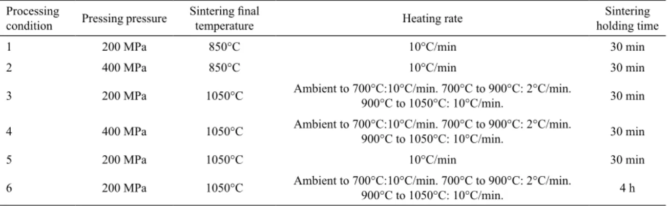
Table 1. Summary of the processing parameters.
Processing
condition Pressing pressure
Sintering final
temperature Heating rate
Sintering
holding time
1 200 MPa 850°C 10°C/min 30 min
2 400 MPa 850°C 10°C/min 30 min
3 200 MPa 1050°C Ambient to 700°C:10°C/min. 700°C to 900°C: 2°C/min. 900°C to 1050°C: 10°C/min. 30 min
4 400 MPa 1050°C Ambient to 700°C:10°C/min. 700°C to 900°C: 2°C/min. 900°C to 1050°C: 10°C/min. 30 min
5 200 MPa 1050°C 10°C/min 30 min
(2)
(3)
where ρ stands for sintered/green density and ρ0 stands for theoretical density.
The average pore size in the sintered parts was determined by the line-intercept method as 1.12L0/Npore using SEM images, where L0 is the line length, and Npore is the number of pores on that line 24. Three lines in two different images were used to determine the pore size using the mentioned method.
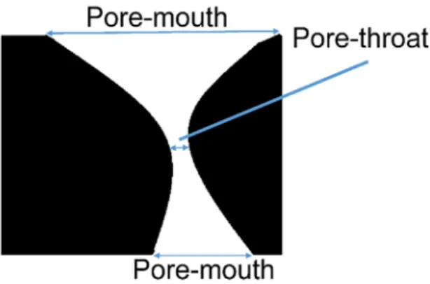
The geometry of a pore can be divided into two different areas of pore-mouth and pore-throat (Fig.1) 25. Large pore-mouth sizes can facilitate bone growth into the porous implants. In addition, a pore-throat should not be too narrow; otherwise, the interconnectivity between the pores is lost. A Porosity Size Distribution Analyser (PSDA), functioning based on the methods explained by Yu and Yan et al. 25,26, was employed to measure the diameter of the smallest pore-throat and largest pore-mouth of the samples.
To increase the accuracy of the results, microstructural experiments such as dimensional, density and open porosity measurements were conducted on three samples and the average values are reported here.
3. Characterization Results
The results of the conducted experiments are explained and analyzed in this section.
3.1- Powder characterization and phase analysis
Based on the results obtained from a laser diffraction particle sizing method, Ti particles (D50 = 24.2 µm) were coarser than Ni particles (D50 = 12.57 µm). Images obtained from SEM were used to determine the morphologies of the powders. Fig.2 shows that Ti powders have spherical morphology while Ni powders are spiky with needle-like texture.
In the first trial, samples were sintered at 850°C for 30 minutes by employing a 10°C/min heating rate, i.e. samples were processed under conditions 1 and 2 (Table 1).
Based on the XRD phase analysis results, sintering the samples at 850 °C (conditions 1 and 2), although successful in forming phases such as NiTi, Ni3Ti, Ni3Ti2 and Ti2Ni, did not result in the complete removal of Ni and Ti elements (Fig.3).
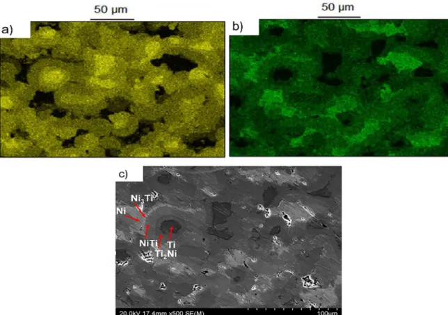
Further SEM/EDS studies and elemental dot mapping were used to confirm the existence of these phases. Since elemental Ni and Ti were detected in samples sintered at 850°C, these samples were not etched for microstructural analysis and same as XRD tests, they were simply grinded and polished. This is because etching could remove these elements from the top layer of the samples. Results obtained from elemental dot mapping clearly showed the existence of Ni-rich and Ti-rich areas. In fact, dark regions in the Ti map are bright regions in the Ni map showing the existence of Ni-rich phases and vice versa (Fig.4.a, b).
Elemental ratios obtained from EDS analysis showed that Ti-rich areas contain ~8 wt.% Ni, suggesting the formation of βTi. These regions were darkest under the SEM images. On the other hand, the brightest areas were Ni-rich, containing ~2-8 wt.% Ti. These areas seem to be the original cores of the Ti and Ni elemental particles, respectively. Based on the results obtained from EDS analysis and interpreting the elemental ratios 27, the region between these two extreme areas are filled with other phases in a gradient way. Areas attributed to elemental Ti were surrounded by Ti-rich Ti2Ni and elemental Ni areas were next to Ni-rich Ni3Ti with a grey NiTi phase in the middle of these areas (Fig.4.c). This gradient phase structure was formed due to solid-state diffusion of elements occurring during the sintering process.
These results indicated that 30 minutes sintering at 850°C is too short to result in complete reaction between these elemental powders. It is expected that sintering at this temperature for longer times will result in complete removal of these elements; however, this strategy was not evaluated in this research. As mentioned before, the aim of this research is to obtain porous parts with approximately 30 Vol.% open porosity. However, the microstructure of these samples (provided in section 3.3) did not show appreciable interconnected porosities and increasing the sintering holding time is expected to result in the shrinkage of pores leading to decreased sintered porosity 17.
R
100
0
#
t
t
=
T Y
1
100
0
#
f
=
T
-
t
t
Y
Figure 1. Schematic of a pore tunnel. Pore geometry can be divided
Figure 3. XRD patterns of samples processed under conditions 1&2
Figure 4. Results of elemental dot mapping (Ti (a) and Ni (b)) and EDS elemental ratio studies (c) on samples processed under condition 2
To achieve fully reacted 60NiTi with a porous structure, the mixed pressed powders were sintered at 1050°C, i.e. above the required temperature of 942°C for generation of eutectic liquid. However, the effect of formation of eutectic liquid on dimensional stability of the samples needed a close attention. The generation of liquid can result in the expansion of the samples altering their initial designed geometry 22. To avoid such a phenomenon, the heating rate was decreased to 2°C/min above 700°C until 900°C. This increased sintering time below 942°C and reduced the amount of elemental Ti that causes liquid generation (conditions 3 and 4, Table 1). Cylindrical samples with stable dimensional sizes were
achieved under these conditions. Despite this, the samples processed under both conditions 3 and 4 could not obtain volumetric open porosity of around 30 Vol.%. The maximum open porosity achieved under these conditions was 23.48 Vol.% (condition 3) (Table 2).
To obtain parts with a greater amount of open porosity, despite concerns regarding the dimensional stability of the parts, samples were heated to 1050°C under a fast heating rate of 10°C/min (condition 5). Results showed that the obtained samples exhibited ~9% volumetric change compared to the 200 MPa pressed powder mixture in the green state. This amount is ~7% more compared to the samples sintered under condition 3 (Table 2). Despite this, these sintered samples could retain their cylindrical shape and no irregularity due to expansion or shrinkage was observed. This sintering procedure resulted in parts with increased open porosity (28.14 Vol.%) compared to condition 3 (Table 2).
Sintering holding time is a factor that can affect the homogeneity of the sintered parts 28. Processing condition 6 was designed to evaluate the effect of this parameter on the homogeneity of sintered 60NiTi samples. The effect of holding time along with other sintering parameters on the homogeneity of samples, their microstructure and generated phases are discussed in the following.
Table 2. Summary of dimensional and microstructural studies.
Condition Diameter
(mm)
Height (mm)
Volume (mm3)
Density
(g/cm3) Open porosity (Volume %)
Total porosity (Volume %)
200 MPa pressed-Not sintered 20.00 7.40 2.32 4.31 Not defined 32.65
400 MPa pressed-Not sintered 20.00 6.84 2.14 4.65 Not defined 27.33
1 20.00 7.24 2.27 4.42 Negligible (Based on microstructural
images) 31.95
2 20.30 6.34 2.05 4.81 Negligible (Based on microstructural
images) 25.92
3 20.60 7.14 2.37 4.14 23.48 36.19
4 21.12 6.56 2.29 4.38 19.41 32.58
5 20.60 7.60 2.53 3.90 28.14 38.83
6 20.42 7.06 2.31 4.29 18.81 33.85
Figure 5. XRD patterns of samples sintered at 1050°C (conditions
3, 4, 5 and 6)
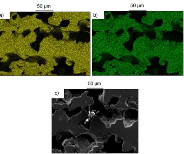
elemental dot mapping (Fig.6.a, b). This map, which was obtained from samples prepared under condition 5 does not show any dramatic uneven distribution of elements as it is the case for samples sintered at 850°C (Fig.4.a, b). The dark areas seen in this map is common for both Ti and Ni so these regions are related to pores where no element exists (Fig.6.c). These all can be attributed to a higher sintering temperature and possible formation of eutectic liquid at 942°C, which due to increased reaction rate results in enhanced homogeneity and crystallinity in samples 28.
For samples sintered at 1050°C, no matter which pressure, heating rate or sintering holding time were used, all samples contained the same phase composition (Fig.5). Obtained peaks could be attributed to NiTi (B2-Austenitic), NiTi (B19’-Martensitic), Ni3Ti, Ni3Ti2 and Ti2Ni. However, the NiTi (B2-Austenitic) peak located at 2θ=~28 could be seen for some conditions, and could not be seen for others sintered at the same temperature of 1050°C (Fig.5). This can be attributed to the orientation effect 29.
EDS elemental analysis was applied to identify NiTi, Ni3Ti, Ni3Ti2 and Ti2Ni phases based on a possible range of elemental ratios in each composition as specified in literature 27. As an example, results of SEM morphological and EDS
elemental analysis are shown for samples sintered under condition 4 (Fig.7).
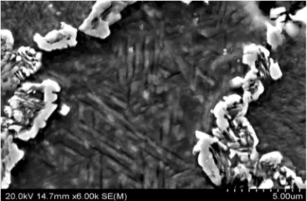
In addition, a fine structure with needle-like contrast was also observed in high magnification SEM images (Fig.8). This is also an evidence indicating the existence of martensitic NiTi in these samples 6. However, Undisz et al. 30 suggested that the surface structures observed on NiTi
alloys need to be interpreted with caution. This is because these structures are not always attributed to the bulk structure and might be artifacts formed due to the effect of etching with hydrofluoric acid.
Ni4Ti3 is another metastable phase that might have been formed due to different reasons such as slow cooling rates upon cooling the sintered parts from 1050°C. However, the existence of this phase cannot be confirmed or denied in furnace cooled as-sintered samples using only XRD and SEM studies. Main XRD peaks of this phase overlap with NiTi (B2) and Ni3Ti phases and also SEM images cannot easily detect this nanoscale phase 6. For these reasons, this research assumes that this phase has not formed during sintering and furnace cooling of the samples. The reasons for the formation of phases such as NiTi2, Ni3Ti2, Ni3Ti and NiTi in two different phase structures of austenitic and martensitic are explained next.
Stable Ni3Ti, Ti2Ni and metastable Ni3Ti2 phases might have been generated due to different causes. Cooling the sintered parts with a slow rate from 1050°C can be considered to be the main cause of the generation of Ni3Ti and Ni3Ti2 phases 5. On the other hand, all the above mentioned phases can be
Figure 6. Results of elemental dot mapping (Ti (a) and Ni (b)) on samples processed under condition 5 (c)
decomposition of the NiTi phase at 620°C during furnace cooling can be considered as another source for the generation of Ni3Ti and Ti2Ni phases 16. Additionally, Ti
2Ni can also be formed during cooling of the sintered parts due to two other sources. In both of these sources, the liquid generated originally at 942°C due to eutectic reaction between βTi and Ti2Ni (βTi + Ti2Ni → L) causes the generation of the Ti2Ni
phase once the parts are being cooled. Peritectic reaction at 984°C between this liquid and NiTi phase (L+NiTi→Ti2Ni) and eutectic solidification (L→βTi + Ti2Ni) at 942°C are these sources 16. However, given the absence of elemental Ti in sintered samples at 1050°C, Ti2Ni generation under eutectic solidification at 942°C is not considered possible. Furthermore, it is estimated that all the liquid produced due
Figure 7. SEM images of sintered samples processed under condition 4. Different phases have been identified based on EDS elemental
Figure 8. High magnification SEM image of sintered samples
processed under condition 4 showing the fine structure with
needle-like contrast attributed to martensitic structure
to the eutectic reaction at 942 °C is reacted and consumed by other phases. As a result, the possibility of the occurrence of peritectic reaction at 984°C is also considered to be negligible.
Based on phase analysis and SEM/EDS studies, in samples sintered at 1050°C, both austenitic and martensitic phase structures are present. NiTi can generally exist in two different phase structures: austenitic and martensitic. Austenite is the phase with an ordered B2 caesium chloride structure and martensitic NiTi has a B19 type structure with a monoclinic or triclinic distortion. Austenite can transform to martensite either thermally or by applying stress. Austenitic NiTi begins to transform thermally to martensitic NiTi when it is cooled below the martensite start temperature (Ms). This diffusionless shear transformation finishes when the temperature is below the martensite finish temperature (Mf) 3,20,22. These phase transformation temperatures are strongly
dependent on the amount of Ni in the NiTi composition 33,34. As Cluff et al. 18 explain, the existence of approximately 50.5 at.% Ni in NiTi composition results in Ms values of approximately room temperature. However, this temperature drops to below -175°C for compositions above 51 at.% Ni. This shows that the amount of Ni in NiTi composition is not uniform and compositional differences exist in the NiTi phase. This may have roots in short sintering holding times resulting in non-uniform distribution of Ni in NiTi composition. In fact, XRD peaks attributed to martensitic NiTi are less intense for samples sintered under 4 hours holding time (condition 6) compared to other conditions (Fig.5). This is evidence for suggesting the role of sintering holding time in compositional homogenization of the sintered parts. Alternatively, the formation of Ni-rich phases such as Ni3Ti results in depletion of Ni from the surrounding NiTi phase making it less concentrated compared to other regions 3. Both the reasons given above result in a gradient of Ni
concentration in the NiTi phase giving opportunity for the formation of NiTi with martensitic and austenitic structures.
3.2 Dimensional stability analysis
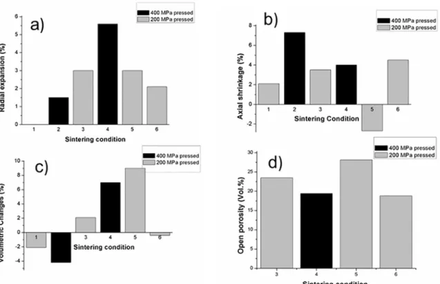
Based on the results obtained in this study, sintered samples, despite showing satisfactory dimensional stability exhibit anisotropy of dimensional change (Table 2). Changes in the length of the sintered samples in the radial (perpendicular to the direction of applied force) and axial (parallel to the direction of the applied force) directions were measured and compared to green samples. In all the conditions, except condition 1, where no change was observed, sintered samples exhibited radial expansion while in all the sintered conditions, except condition 5, sintered samples demonstrated axial shrinkage (Fig.9.a, b).
The anisotropy of dimensional change seen in the sintered samples is explained with the mechanism suggested by Igharo 22.
Based on this mechanism, for the samples sintered below 942°C, which is the temperature at which eutectic liquid forms, the diffusion is occurring in solid state. Considering the schematic of the segregated powder structure, faster diffusion of Ni compared to Ti (in solid state) will result in a general positive flux of atoms toward the Ti particles. This will lead to an expansion in the radial direction (Fig.10.a).
On the other hand, powder particles experience self-diffusion during solid state sintering. This is mainly because the same powder type particles are touching each other due to the difference in particle size, as illustrated in the schematic diagram Fig.10.b. This self-diffusion between the same powder types (i.e. Ni-Ni and Ti-Ti) results in neck-growth and consequently axial shrinkage 22.
Conversely, when the sintering temperature is above 942°C, the generation of eutectic liquid and its subsequent penetration along the capillaries results in the expansion of parts in both radial and axial directions 22.
Considering this mechanism, the results obtained in this study can be interpreted as follows: As expected, the samples sintered at 850°C (conditions 1 and 2), because they are sintered under solid-state diffusion, exhibit axial shrinkage. In addition, the magnitude of the axial shrinkage increases with increasing compaction pressure. This is because, under higher pressure, particles touch each other more strongly with the effect that the amount of self-diffusion, and consequently, necking increases compared to samples pressed under lower pressures.
Conforming the mechanism explained by Igharo 22, the samples processed under condition 2 exhibited radial expansion. However, the samples processed under condition 1 did not show any measurable radial change. In addition, the magnitude of radial expansion for the samples processed under condition 2 was less than their axial shrinkage. This means that axial shrinkage and the necking effect are more prominent than radial expansion in 60NiTi parts sintered under solid-state diffusion.
Figure 9. Graphs showing a) radial expansion of the sintered samples compared to green sample, b) axial shrinkage of the sintered samples compared to green samples, c) volumetric changes of sintered samples compared to green samples and d) amounts of open porosity in sintered samples
Figure 10. Schematic showing the interaction between the particles
sintered below 9420C a) general positive flux of Ni atoms toward the
Ti particles in the radial direction and b) powder particles touching
each other resulting in self-diffusion and axial shrinkage
condition 2. This is attributed to the effect of the liquid generated above 942°C, which results in expansion of the parts. However, the axial shrinkage increased in samples processed under condition 3 compared to condition 1. This means that in samples processed under the lower pressure of 200MPa, the effect of solid-state diffusion causing necking and subsequently axial shrinkage overcompensates for the effect of liquid generation. On the other hand, samples processed under condition 5, which are sintered samples with faster heating rates, exhibited axial expansion. This could be due to the generation of more eutectic liquids in parts processed under faster heating rates compared to
parts processed under slower heating rates, leading to axial expansion of parts processed under condition 5.
On the other hand, the effect of liquid generation on the radial expansion of the parts can clearly be observed when sintered at 1050°C. Parts processed under conditions 3 (in contrast to the shrinkage observed in radial direction) exhibited increased radial expansion compared to parts processed below 850°C. Moreover, the amount of radial expansion in samples processed under condition 3 (processed under a slow heating rate) is the same as with condition 5 (processed under a fast heating rate). In addition, for samples processed under condition 4, the rate of increase in radial expansion is more than the rate of axial expansion. These suggest the eutectic liquid generated at a temperature above 942°C has more tendency to move radially than axially in sintered parts.
Volumetric change of the samples is the result of a combination of their radial and axial changes. As seen in Fig.9.c, samples sintered at 850°C were contracted compared to green samples. However, sintering the samples at 1050°C for 30min resulted in an expansion of the samples compared to green samples (conditions 3, 4 and 5). The volume increase was greater under condition 5 where a larger amount of liquid is estimated to be generated while sintering above 942°C.
to the effect that sintering holding time plays in contraction of the original pores resulting in shrinkage of the sintered parts 17.
Volumetric change directly affects the density and amount of porosity in the samples. The contraction in samples compared to the green state leads to samples with increased density and decreased porosity. The opposite result is achieved when samples are expanded (Table 2). The highest amount of density was achieved for samples processed under condition 2. This amount of density corresponds to a theoretical density of 74%.
3.3 Microstructural analysis
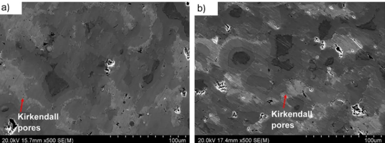
Different sources can result in the generation of pores in the sintered samples. Depending on some parameters such as powder size, powder morphology and applied compaction pressure, some pores are originally formed in compacted green samples. As Chen et al. 31 explain, phase transformations are considered as another source for the generation of porosity. Some phase transformations could cause volumetric changes resulting in shrinkage and subsequently porosity generation. Furthermore, solid-state diffusion of elements during sintering is another source for the generation of a specific type of porosity. This phenomenon known as Kirkendall effect is due to the faster diffusion rate of Ni compared to Ti. This difference in diffusion rate leads to the generation of voids in original elemental Ni areas 28,31,35.
Kirkendall pores can clearly be observed in samples processed under conditions 1 and 2, where the sintering is done under solid-state diffusion (Fig.11). While in samples sintered at 1050°C, the generated liquid can fill these voids.
Despite this, the total amount of porosity in samples processed under conditions 1 and 2 are decreased compared to their initial non-sintered state. As explained in the previous section, contraction in samples compared to their original green state leads to samples with increased density and decreased porosity (Table 2).
Figure 11. SEM images obtained from samples processed under a) condition 1 and b) condition 2
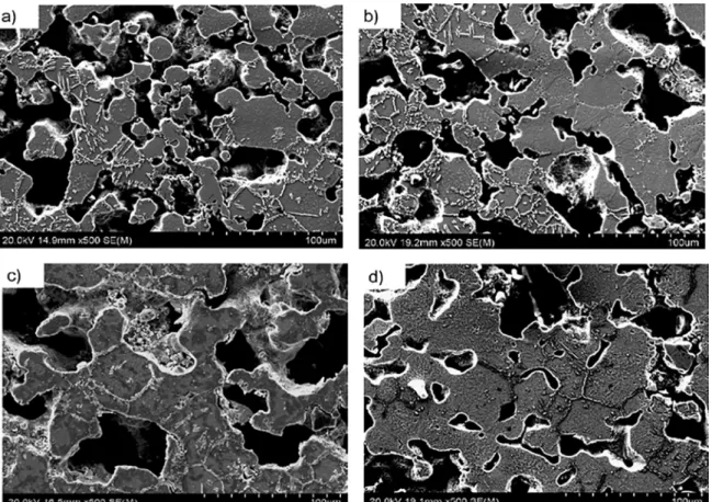
On the other hand, the geometries of pores in samples sintered at 1050°C are quite different compared to samples sintered below 942°C (Fig.12). Microstructures of these samples are quite porous with significant amounts of interconnected porosities. This is because liquid is generated in samples processed under these circumstances and its movement results in the generation of pores afterwards.
For samples processed under conditions 3, 4 and 5, the samples processed under lower compaction pressure exhibited higher open porosity compared to the samples processed under the higher compaction pressure of 400MPa (Fig.9.d). In addition, the amount of open porosity in samples processed under condition 5 (28.14 Vol.%) was higher than samples processed under condition 3 (23.14 Vol.%). This is because a greater amount of eutectic liquid is formed under this condition due to faster heating rates applied during sintering. In fact, the maximum amount of open porosity (~28 Vol.%) was obtained in samples processed under this condition (condition 5). Moreover, an increase in the sintering holding time results in a drop of the open porosity amount as it leads to increased density and decreased porosity. These results indicate that sintering above 942°C, fast sintering heating rates and decreased sintering holding times is beneficial in terms of producing parts with an increased amount of open porosity.
As explained before, based on the requirements needed for implants suitable for general bone replacement applications, it is desirable that pore sizes are in the range 100-600 µm 15. Obtained results showed that the maximum pore-mouth
Figure 12. Microstructure of samples processed under a) condition 3, b) condition 4, c) condition 5 and d) condition 6
Table 3. Summary of porosity characteristics in samples sintered
at 1050°C.
Condition Average pore
size (µm)
smallest pore-throat size (µm)
Largest pore-mouth size
(µm)
3 138.00 10.60 147.61
4 107.00 8.70 120.42
5 123.00 31.88 169.48
6 87.81 9.91 106.41
important role of sintering process parameters for designing the porosity characteristics of parts.
4. Conclusions
In this research, the conventional press-and-sinter method was employed to produce porous 60NiTi samples suitable for general bone replacement applications where bone diffusion is desirable. Different process parameters such as compaction pressure, sintering heating rate, sintering final temperature and sintering holding time were altered to obtain porous parts with ~30 Vol.% amount of open-porosity. It was found that liquid formed due to sintering of the parts above 942°C plays a positive role in homogenization of the parts and results in generation of open porosities. Applying a fast heating rate of 10°C/min resulted in increased amounts of open porosity as
it possibly caused generation of more liquid compared to the situation where a slower heating rate was applied. However, the effect of liquid generation on the expansion of the parts need to be considered so as to ensure that parts with good dimensional stability are manufactured. In addition, it was concluded that the eutectic liquid generated at a temperature above 942°C has more desire to move radially than axially in sintered parts.
Compaction pressure is another factor which plays a role in the amount of generated open porosities. Lower compaction pressures result in increased porosity in green samples leading to higher open porosity in final parts. On the other hand, sintering holding time is a factor that, despite its positive role in homogenization of the samples, decreases the amount of open porosity, as it results in volume shrinkage and enhanced density of the sintered parts. For samples sintered at 1050°C, no matter which pressure, heating rate or sintering holding time used, the phase constituents were the same and all Ni and Ti elemental materials were removed.
of 1050°C, which is above the temperature required to generate eutectic liquid, a fast heating-rate of 10°C/min during sintering and a short sintering holding time of 30 min.
Solutionizing treatment would be the next step in producing hard and biocompatible 60NiTi parts. Existence of Ni3Ti and Ni3Ti2 phases in the matrix makes as-sintered samples unsuitable for biomedical applications as they act as preferential corrosion sites and make 60NiTi prone to corrosion. It is expected that these non-desirable phases existing in as-sintered parts will be mostly removed after applying a final solutionizing treatment. Further, the amount of open porosity is estimated to increase during the rapid cooling of quenching process. However, the rapid cooling rates applied during the quenching process lead to residual thermal stresses that sometimes result in cracking in even fully dense 60NiTi parts. The effects of solutionizing treatments on such porous samples needs to be investigated in further research.
5. Acknowledgment
The authors would like to thank Patrick Conor, Auckland University of Technology, for his assistance in conducting SEM studies.
6. References
1. DellaCorte C, Noebe R, Stanford M, Padula S. Resilient and
corrosion-proof rolling element bearings made from superelastic Ni-Ti alloys for aerospace mechanism applications. In: ASTM
2011 Symposium on Rolling Element Bearings; 2011 Apr 13-15; Los Angeles, CA, USA.
2. Stanford MK. Hardness and Microstructure of Binary and
Ternary Nitinol Compounds. Report NASA/TM-2016-218946.
Hampton: NASA Langley Research Center; 2016.
3. Adharapurapu RR. Phase transformations in nickel-rich
nickel-titanium alloys: influenece of strain-rate, temperature,
thermomechanical treatment and nickel composition on the shape memory and superelastic characteristics. [Dissertation].
San Diego: University of California; 2007.
4. Otsuka K, Ren X. Physical metallurgy of Ti-Ni-based shape
memory alloys. Progress in Materials Science. 2005;50(5):511-678.
5. Hornbuckle BC, Yu XX, Noebe RD, Martens R, Weaver ML,
Thompson GB. Hardening behavior and phase decomposition in very Ni-rich Nitinol alloys. Materials Science and Engineering:
A. 2015;639:336-344.
6. Bertheville B, Neudenberger M, Bidaux JE. Powder sintering and shape-memory behaviour of NiTi compacts synthesized from Ni and TiH2. Materials Science and Engineering: A.
2004;384(1-2):143-150.
7. Benafan O, Garg A, Noebe RD, Skorpenske HD, An K, Schell
N. Deformation characteristics of the intermetallic alloy 60NiTi. Intermetallics. 2017;82:40-52.
8. Thomas F. The Effect of Various Quenchants on the Hardness and Microstructure of 60-NITINOL. Report
NASA/TM-2015-218463. Hampton: NASA Langley Research Center; 2015. 9. Adharapurapu RR, Vecchio KS. Superelasticity in a New
Bioimplant material: Ni-rich 55NiTi alloy. Experimental Mechanics. 2007;47(3):365-371.
10. DellaCorte C, Moore LE III, Clifton JS. Static Indentation
Load Capacity of the Superelastic 60NiTi for Rolling Element Bearings. Report NASA/TM-2012-216016. Hanover (MD):
NASA Center for AeroSpace Information; 2012.
11. DellaCorte C, Moore LE III, Clifton JS. The effect of Pre-Stressing
on the Static Indentation Load Capacity of the Superelastic 60NiTi. Report NASA/TM-2013-216479. Hanover (MD):
NASA Center for AeroSpace Information; 2013.
12. Della Corte C, Howard SA, Thomas F, Stanford MK. Microstructural and Material Quality Effects on Rolling Contact
Fatigue of Highly Elastic Intermetallic NiTi Ball Bearings.
Report NASA/TM-2017-219466. Hampton: NASA Langley Research Center; 2017.
13. Della Corte C, Moore LE III. Launch Load Resistant Spacecraft Mechanism Bearings Made From NiTi Superelastic Intermetallic
Materials. In: Proceedings of the 42th Aerospace Mechanisms Symposium; 2014 May 14-16; Baltimore, MD, USA.
14. Khanlari K, Ramezani M, Kelly P. 60NiTi: A Review of Recent Research Findings, Potential for Structural and Mechanical
Applications, and Areas of Continued Investigations. Transactions
of the Indian Institute of Metals. 2018;71(4):781-799.
15. Bansiddhi A, Sargeant TD, Stupp SI, Dunand DC. Porous NiTi
for bone implants: A review. Acta Biomaterialia. 2008;4(4):773-782.
16. Chen G, Liss KD, Cao P. In situ observation and neutron diffraction
of NiTi powder sintering. Acta Materialia. 2014;67:32-44.
17. Li BY, Rong LJ, Li YY. Porous NiTi alloy prepared from elemental powder sintering. Journal of Materials Research.
1998;13(10):2847-2851.
18. Cluff D, Corbin SF. The influence of Ni powder size, compact composition and sintering profile on the shape memory
transformation and tensile behaviour of NiTi. Intermetallics.
2010;18(8):1480-1490.
19. Whitney M, Corbin SF, Gorbet RB. Investigation of the influence of Ni powder size on microstructural evolution and the
thermal explosion combustion synthesis of NiTi. Intermetallics.
2009;17(11):894-906.
20. Chen G. Powder metallurgical titanium alloys (TiNi and
Ti-6Al-4V): injection moulding, press-and-sinter, and hot pressing.
[Thesis]. Auckland: The University of Auckland; 2014. 21. Chen G, Liss KD, Cao P. An in situ Study of NiTi Powder
Sintering Using Neutron Diffraction. Metals.
2015;5(2):530-546.
22. Igharo M, Wood JV. Compaction and Sintering Phenomena in
Titanium-Nickel Shape Memory Alloys. Powder Metallurgy.
1985;28(3):131-139.
23. ASTM International. ASTM B962-08 - Standard Test Methods
Products Using Archimedes' Principle. West Conshohocken:
ASTM International; 2008.
24. Bansiddhi A, Dunand DC. Shape-memory NiTi foams produced
by replication of NaCl space-holders. Acta Biomaterialia.
2008;4(6):1996-2007.
25. Yu J, Hu X, Huang Y. A modification of the bubble-point method
to determine the pore-mouth size distribution of porous materials.
Separation and Purification Technology. 2010;70(3):314-319.
26. Yan H, Jian Y, inventors; Nanjing University of Science and
Technology, assignee. Method of Determining Surface Pore Mouth Diameter Distribution of Porous Material . United
States patent US20110167897A1. 2011 Jun 14.
27. Della Corte C, Glennon GN, inventors; Abbott Ball Co, National Aeronautics and Space Administration (NASA), assignee.
Ball Bearings Comprising Nickel-Titanium and Methods of Manufacturing Thereof. United States patent US8182741B1. 2012 May 22.
28. Green SM, Grant DM, Kelly NR. Powder Metallurgical
Processing of Ni-Ti Shape Memory Alloy. Powder Metallurgy.
1997;40(1):43-47.
29. Hey JC, Jardine AP. Shape memory TiNi synthesis from
elemental powders. Materials Science and Engineering: A.
1994;188(1-2):291-300.
30. Undisz A, Reuther K, Reuther H, Rettenmayr M. Occurrence and origin of non-martensitic acicular artifacts on NiTi. Acta Materialia. 2011;59(1):216-224.
31. Chen G, Liss KD, Cao P. In Situ Observation of Phase Transformation of Powder Sintering from Ni/TiH2 Using
Neutron Diffraction. In: TMS 2014: 143rd Annual Meeting & Exhibition; 2014 Feb 16-20; San Diego, CA, USA. Cham:
Springer; 2014.
32. Zhu SL, Yang XJ, Fu DH, Zhang LY, Li CY, Cui ZD. Stress-strain behavior of porous NiTi alloys prepared by
powders sintering. Materials Science and Engineering: A.
2005;408(1-2):264-268.
33. Ingole S. 60NiTi Alloy for Tribological and Biomedical
Surface Engineering Applications. JOM.
2013;65(6):792-798.
34. DellaCorte C. Nickel-Titanium Alloys: Corrosion" Proof" Alloys for Space Bearing, Components and Mechanism
Applications. In: Proceedings of the 40th Aerospace Mechanisms Symposium; 2010 May 12-14; Cocoa Beach,
FL, USA.