Video Denoising based on Stationary Wavelet Transform and Center Weighted Median
Filter
Soundarya K
Submitted in May, 2013, Accepted in February, 2014
Abstract - Noise removal using wavelet has the characteristic of preserving signal uniqueness even if noise is going to be minimized. Images are getting corrupted by impulse noise during image acquisition and transmission. A new median filter termed as the center weighted median filter (CWMF) in the wavelet coefficient domain combined with stationary wavelet transform (SWT) is proposed for video denoising. This filter iteratively smoothes the noisy wavelet coefficients variances preserving the edge information contained in the large magnitude wavelet coefficients. This Paper deals with uncompressed video of .avi format. The proposed algorithm works well for suppressing Gaussian noise with noise density from 10 to 70% while preserving image details. Simulation results show that higher peak signal to noise ratio can be obtained as compared to other recent image denoising methods.
Index Terms – Denoising, SWT, CWMF, PSNR and MSE
1.0 INTRODUCTION
Many scientific datasets are contaminated with noise, either because of the data acquisition process, or because of naturally occurring phenomena. Preprocessing is the first step in analyzing such datasets [3]. There are several different approaches to denoise images. The main problem faced during diagnosis is the noise introduced due to the consequence of the coherent nature of the image capture. In image processing applications, linear filters tend to blur the edges and do not remove Gaussian and mixed Gaussian impulse noise effectively [4]. Gaussian noise is an additive noise, which degrades image quality that originates from many microscopic diffused reflections leads to discriminate fine detail of the images in diagnostic examinations. Noise represents unwanted information which destroys image quality. The noise usually corrupts images by replacing some of the pixels of the original image with new pixels having luminance values near or equal to the minimum or maximum of the allowable dynamic luminance range. In Gaussian noise each and every pixel of the image gets affected. Image denoising is the method of removing unwanted noise from the corrupted images. Several
Department of EEE, PSG College of Technology, Coimbatore, India
E-mail: [email protected]
filters are used for denoising the images. The main goal of the filtering process is to remove noise while preserving edges and image detail information. In general image denoising provides the quality images by increasing the PSNR values.
are given in Section 5. Finally Conclusion and reference are discussed in Section 6.
2.0 STATIONARY WAVELET TRANSFORM
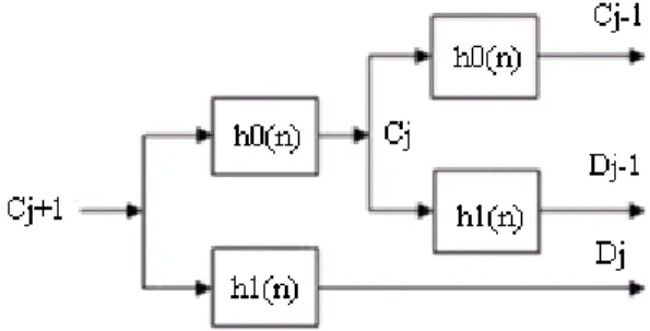
A tool for the analysis of transient, non-stationary or time varying phenomena that has energy concentrated in time is a wavelet. The SWT can be obtained by modifying the basic DWT algorithm [1], [2]-[3]. The DWT does not preserve translation invariance due to sub-sampling operations in the pyramidal algorithm. The SWT has been introduced because it preserves the property that a translation of the original signal does not necessarily imply a translation of the corresponding wavelet coefficients. To halve the bandwidth from one level to another level, the SWT utilizes recursively dilated filters instead of subsampling. The stationary wavelet transform (SWT) was introduced in 1996 to make the wavelet decomposition time invariant [5]. This improves the power of wavelet in signal de-noising. This paper exploits the benefits of stationary wavelet transform in suppressing noise at high frequencies and median filter to suppress noise in low frequency bands. The proposed algorithm is divided into two steps. After taking SWT to the noisy image, soft thresholding method is applied to the details subbands; then a transformed image is generated from approximation subband only while the other subbands are made equal to zero, applying inverse SWT to the generated 2-D array, then applying the weighted median filter, to remove the residual noise in the low frequency band. After that the approximation band is returned by applying SWT to the denoised signal, the resulted approximation subband is grouped with the thresholded subbands, applying inverse SWT to obtain the denoised image.
Fig. 1 Wavelet Decomposition
The SWT is an inherent redundant scheme, as each set of coefficients contains the same number of samples as the input. So for a decomposition of N levels, there is a redundancy of 2N. At each level, when the high-pass and low-pass filters are applied to the data, the two new sequences have the same length as the original sequences. To do this, the original data is not decimated. However, the filters at each level are modified by padding them out with zeros. However, for stationary or redundant transform, instead of downsampling, an upsampling procedure is carried out before performing filter convolution at each scale. The Discrete Wavelet Transform (DWT) is the simplest way to implement MRA. It necessitates decimation by a factor 2N, where N stands for the level of decomposition, of
the transformed signal at each stage of the decomposition. As a result, DWT is not translation invariant which leads to block artifacts and aliasing during the fusion process between the wavelet coefficients. For this reason, we use the Stationary Wavelet Transform (SWT). For the SWT scheme the output signals at each stage are redundant because there is no signal down- sampling; insertion of zeros between taps of the filters are used instead of decimation.
3.0 CENTER WEIGHTED MEDIAN FILTER
The standard median filter is a simple rank selection filter that attempts to remove impulse noise by changing the luminance value of the center pixel of the filtering window with the median of the luminance values of the pixels contained within the window [7]. Although the median filter is simple and provides a reasonable noise removal performance, it removes thin lines and blurs image details even at low noise densities. Median filter replace every pixel of the image by the median value of its neighborhood. The filter performs well for noise densities less than 50% above which the noise present in the neighborhood is more than the information and hence the filter’s performance deteriorates [8]. Fig. 2 describes the function of Median Filter.
Sorted Pixel values: 3, 3, 4, 4, 4, 5, 5, 87 Median Filtered value: 4
Fig. 2 Median Filter 3.1 Median Filter
It provides better removal of impulse noise from corrupted images. It replaces the center value with the median of all the pixels in the window. According to window size each pixels in the window is taken and sort the pixel then find the median of the each window. Then this median value is replaced by center value.
3.2 Weighted Median Filter
The basic idea is to give weight to the each pixel. Every pixel is given a weight. This weight is multiply with pixel. According to this weight the pixels are sort into ascending order, and then find the median value from the sorted list. This value is replaced with center value.
3.3 Center Weighted Median Filter
value available in window then center pixel is considered as corrupted pixel [10]. This corrupted pixel is replaced by calculated value. Weight is given to the center pixel then sorts all element of window in ascending order and calculate median of elements. The weighted median filter and the center weighted median filter are modified median filters that give more weight to the appropriate pixels of the filtering window. These filters have been proposed to avoid the inherent drawbacks of the standard median filter by controlling the tradeoff between the noise suppression and detail preservation. When one give more weight to the central value of the window a special case of weighted median filters called the Center Weighted Median filter will be produced, and thus it is easier to design and implement the general weighted median filters [9]. Obviously, a center weighted median filter with a larger central weight performs better in detail preservation than with a smaller central weight. The central weight should be carefully selected depending on the characteristics of the input image and its noise. The advantage of center weighted median filter is to reduce noise and to preserve fine details.
4.0 PROPOSED SYSTEM
In the hybrid work, two techniques namely, wavelet thresholding and center weighted median filters are combined to form a hybrid denoising model. The proposed method performs median filtering on the wavelet coefficients to denoise an image degraded by Gaussian Noise. These techniques are used to suppress the Gaussian noise. This Paper only deals with uncompressed video of .avi format. Fig.3 describes the process of noise removal.
Figure 3: Noise removal process
Wavelets have made quite a splash in the field of image processing. Proposed model is the newly designed hybridized one as shown in fig.4. In this model, the image is denoised first with wavelet decomposition into four sub-bands using haar wavelet filters. It is used for suppressing the Gaussian noise. Resultant coefficients are used for image reconstruction with IWT. The results obtained after inverse transform are then used to reconstruct the image. In the last level, center weighted median filter is used to remove noise present in the image during transformation. The final denoised image is obtained. Wavelets work for decomposing signals into hierarchy of increasing resolutions. The advantage of wavelet denoising is possible to remove the noise with little loss of details. The wavelet mode denoises only the Gaussian type of noise. So when multiple noise present in the image it will remove only
Gaussian the remaining noise are unremoved. So for removing the remaining noise and to preserve the fine details CWM filter is applied. The advantage of center weighted median filter is that it can denoise the large window size.
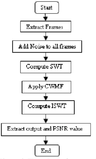
Figure.4: Flow chart of proposed system
The proposed algorithm is described in this section; it is applied for each (Red, Green, and Blue) band separately. It consists of the following steps:
1- Read the noisy color image
2- Apply SWT (one level of decomposition)
3- Reconstruct a new image from LL1 subband only while making other subbands equal to zero, by applying inverse stationary wavelet transform.
4- Apply center weighted median filter to the reconstructed image in spatial domain.
5- Reapplying SWT to the resultant image of step 4.
6-Apply inverse stationary wavelet transform, to get the denoised image.
5.0 RESULTS AND DISCUSSIONS
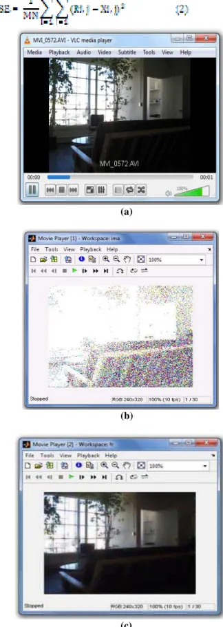
The video used for testing this algorithm is acquired from “http://www.frequency.com/video”. The performance of the proposed algorithm is tested for various levels of noise corruption and compared with the Existing algorithms. The algorithm is implemented in MATLAB 7.2 on a PC equipped with 2.4 GHz CPU and 2 GB RAM memory for the evaluation of computation time of algorithms. The Quantitative performance of the proposed algorithm is evaluated frame by frame based on Peak signal to noise ratio and Mean Square Error which is given in (1) and (2) respectively.
(a)
(b)
(c)
Figure 5 (a) Input Video (b) Video corrupted by random noise with 30 Percent noise density and (c) Restored Video
Noise Density
(%)
Existing System Proposed System
PSNR (db) DTCWT
PSNR (db)
DDDTCWT PSNR (db)
10 34.3432 32.3623 43.0659 20 32.9458 31.5489 40.7863 30 29.6963 30.4888 38.9385 50 28.5542 28.8194 35.5476 70 28.1860 28.2885 32.4698
Table 1: PSNR for different noise densities
In addition to the visual quality, the performance of the developed algorithm and other standard algorithms are quantitatively measured by the following parameters such as peak signal to noise ratio (PSNR) and Mean square error (MSE). The proposed algorithm shows excellent noise suppression and edge preservation capabilities. The proposed algorithm effectively removes the random noise and preserves edges for low, medium and high detail images. Fig. 5 describes the graph plot between PSNR value and noise density for different algorithms [13].
Figure 6: Graph between Existing and Proposed system
6.0 CONCLUSIONS
A new technique based on the hybridization of stationary wavelet transform and center weighted median filters for denoising a noisy video. Results prove that utilization of center weighted median filters in combination with stationary wavelet transform deteriorates the performance. By using this technique, the noise is getting reduced and also we can get the originality of the image. The proposed filter gives suitable results on the basis of PSNR and MSE. Experimental results indicate that the proposed method performs significantly better than many other existing techniques. The proposed method is simple and easy to implement. As noise increases the proposed methodology works superior than other algorithms.
REFERENCES
[1]. Abdullah Al Jumah, “Denoising of an Image using Discrete Stationary Wavelet Transform and Various Thresholding Techniques”, Journal of Signal and Information Processing, Vol. 4, pp:33-41, 2013.
[2]. Iman M.G. Alwan, “Color Image Denoising using Stationary Wavelet Transform and Adaptive Wiener Filter”, Al-Khwarizmi Engineering Journal, Vol. 8, No. 1,pp:18 -26, 2012.
[3]. S. Ruikar, Andria and D. D. Doye, “Image Denoising using Wavelet Transform,” International Conference on Mechanical and Electrical Technology, Singapore City, 10-12, pp. 509-515, September 2010,
[4]. Mamta Juneja, Rajni Mohana, “An Improved Adaptive Median Filtering Method for Impulse Noise Detection”, International Journal of Recent Trends in Engineering, Vol. 1, No. 1, May 2009.
[5]. Rosebell John and V. Karunakaran, “A Survey on Denoising Methods”, IOSR Journal of Engineering,
Volume 2, Issue 10, pp: 85-89, October 2012.
[6]. J Umamaheswari and Dr.G.Radhamani, “Hybrid Denoising Method for Removal of Mixed Noise in Medical Images”, International Journal of Advanced Computer Science and Applications, Vol. 3, No. 5, 2012. [7]. R. Marudhachalam and Gnanambal Ilango, “Fuzzy
Center Weighted Hybrid Filtering Techniques for Denoising of Medical Images”, International Journal of Fuzzy Mathematics and Systems, ISSN 2248-9940 Vol. 2, No. 4, pp. 383-390, 2012.
[8]. S.M. Mahbubur Rahman, Md. Kamrul Hasan, “Wavelet-Domain Iterative Center Weighted Median Filter for Image Denoising “, ELSEVIER, Signal Processing 83, 1001 – 1012, 2003.
[9]. Behrooz Ghandeharian, Hadi Sadoghi Yazdi and Faranak Homayouni, “Modified Adaptive Center Weighted Median Filter for suppressing impulsive Noise in Images”, International Journal of Research and Reviews in Applied Sciences ISSN: 2076-734X, EISSN: 2076-7366 Vol. 1, Issue 3, and December 2009.
[10]. Aparna Madhavrao Harale and J.S.Chitode, “Analyze performance of Median Filter and Center Weighted Median Filter for Efficient Removal of Impulse Noise
Using ARM”, International Journal of Engineering and Advanced Technology, ISSN: 2249 – 8958, Vol.-2, Issue-4, April 2013.
[11]. B.Chinnarao and M.Madhavilatha, “Improved Image Denoising Algorithm using Dual Tree Complex Wavelet Transform”, International Journal of Computer Applications (0975–8887) Vol. 44–No20, April2012. [12]. RC Patil, “Image Retrieval using 2D Dual Tree Discrete
Wavelet Transform”, International Journal of Computer Applications (0975– 8887), Vol. 14 ,No.6, February2011.
[13]. Mr. R. K. Sarawale, Dr. Mrs. S.R. Chougule, ”Image Denoising using Dual-Tree Complex DWT and Double-Density Dual-Tree Complex DWT”, International Journal of Advanced Research in Computer Engineering & Technology, Vol. 2, Issue 6, June 2013.
[14]. S. K. Muttoo, Sushil Kumar, "Robust Source Coding Steganographic Technique Using Wavelet Transforms", BIJIT - BVICAM's International Journal of Information Technology, Vol.1 No.2, July - December, 2009. [15]. S. K. Muttoo, Sushil Kumar, "Data Hiding in JPEG
Images", BIJIT - BVICAM's International Journal of Information Technology, Vol.1, No. 1, Jan 2009.