E
NERGY AND
E
NVIRONMENT
Volume 7, Issue 5, 2016 pp.417-426
Journal homepage: www.IJEE.IEEFoundation.org
Four MATLAB-Simulink models of photovoltaic system
Jawad Radhi Mahmood
1, Nasir Hussein Selman
21
Electrical Engineering Department, College of Engineering, Basrah University, Ministry of Higher Education & Scientific Research, Basrah, Iraq.
2
Communication Engineering Department, Technical Engineering College/Najaf, Al-Furat Al-Awsat Technical University, Ministry of Higher Education & Scientific Research, Najaf, Iraq.
Abstract
This paper presents four different MATLAB models to simulate the output I-V and P-V characteristics of photovoltaic (PV) cells or systems. All of the models are implemented with Matlab-Simulink. Detailed modeling procedure for one-diode equivalent circuit model with all equations and numerical values is presented. The parameters required for the modeling have been taken from manufacturer's datasheet for 240W SOLIMPEKS solar panel. I-V and P-V characteristics of a typical 1.92 kW PV system have been simulated using the proposed models. The simulation took into account the sunlight insolation and temperature effect. Results of the models are validated with I-V and P-V curves provided by the manufacturer(s). The proposed models are very useful for those interested in working in the field of solar systems because they emulate and analyze the characteristics of all the solar systems easily.
Copyright © 2016 International Energy and Environment Foundation - All rights reserved.
Keywords: Photovoltaic (PV) cell; PV module; PV characteristics; Standard test conditions (STC); MATLAB/Simulink.
1. Introduction
In spite of the fluctuation of sunlight, the energy produced by PV effect is considered the most forefront and essential resources for renewable energies, because of the sustainability and abundance of the sun's energy [1].
PV cells directly convert sun energy into electrical energy by PV effect, without any contamination and environmental impact. These cells are connected in series to form PV string (for raising the voltage) and the strings are connected in parallel to get high current PV module or panel. Arrays are the outcome of a series and parallel combination of PV modules [2].
The output power of solar panel depends mainly on the solar irradiance and the panel temperature. Typically with increasing the PV panel temperature, the current increases slightly while the voltage decreases more than the current. The resultant effect is PV power reduction. The PV generated current is directly proportional to the solar insolation whereas the voltage expose little change [3].
There are three major technologies of PV cells manufacturing. These are Monocrystalline, Polycrystalline, and Thin film technologies. Monocrystalline technology's efficiency ranging from 10% to 15%, while the efficiency of the polycrystalline and thin film technologies range from 9% and 12% [4].
systems, for modeling, analyzing and solving dynamic real problems. The simulation of PV cell can be implemented in MATLAB-Simulink software with different methods. The design model of solar system is being continuously developed to make researchers understand more about how its work. Many researchers have been trying to develop a suitable simulation model for PV cell [1-10].
The objective of this paper is to develop well clear and understandable MATLAB-Simulation PV models in which the insolation and temperature levels form key factors.
2. PV cell model
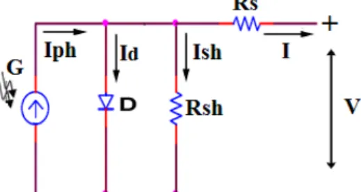
The adopted model should presents high degree of emulate and at the same time require less or acceptable calculation. To fulfill these two requirements single diode model has been used. The equivalent electrical circuit of this model is shown in Figure 1. It consists of a current source, diode, shunt resistor (Rsh) and series resistor (Rs)[5].
Figure 1. Single diode equivalent circuit of the PV cell.
The photocurrent (Iph) of the current source depends on the solar insolation (G) and PV cell’s operating temperature (Top) [4]. This current is given as:
)] ( [ ref T op T I K I ref G G ph
I sc (1)
Where Gref and Tref are insolation and temperature at STC respectively (STC are 1000W/m2 and 25C o
), Isc is the cell short circuit current at STC and KI is the current temperature coefficient.
The output current (I) of this solar cell model can be written as [6]:
sh
I
d
I
ph
I
I
(2)Where Id is the diode current and Ish is the current through Rsh which are illustrated by equations (3) and (4) respectively
] 1 )
[exp(
t s sat d nV IR V I I (3) sh s sh R IR V
I (4)
Where Isat is the reverse saturation current of diode, V is terminal voltage, n is the ideality factor of diode, and Vt is the thermal voltage (Vt= kT/q), (q= 1.6 ×10⁻¹⁹ C is the charge of electron, k= 1.38 ×10⁻²³J/K
is Boltzmann’s constant).
Isat varies with the temperature, which is given as [3, 7]:
)] 1 1 ( exp[ ) ( 3 T T nk qE T T I I ref g n ref Rs
Where Eg is the band gap energy of the semiconductor used in the PV cell. IRS is the cell’s reverse saturation current at STC which can be approximated as:
1 ) exp( ref s oc sc RS knT N qV I I (6)
Where Voc represents open circuit voltage and Isc the short circuit current at STC. The ideality factor of diode (n) is dependent on PV technology [8].
Substitute eqs. (3) and (4) in eq. (2) yields:
sh s t s sat ph R IR V nV IR V I I
I [exp( )1] (7)
The above voltage-current equation of the PV cell is non-linear equation that gives the I-Vcharacteristic of the PV cell.
3. PV module and array
The voltage generated by a unique PV cell is not adequate for general use since it generates voltage less than 0.8V. Therefore, the PV cells must be connected in series and parallel combination to produce higher voltage and power. Generally, a combination of a series and parallel of PV cells is called as a module or panel. Most PV modules involve 36 or 72 PV cells. A PV array is a series and parallel configuration of modules. The equivalent circuit for the PV array arranged in (NP) parallel strings and (NS) series cells in each string is shown in Figure 2. Thus, eq. (7) can be conveniently scaled to get a similar equation for the IV characteristic of a PV module, and array, as following [4]:
sh S S P t P S S sat P ph P R I R V N N nV N I R N V I N I N I
[exp( ) 1] (8)
Figure 2. Generalized array model [4].
4. Characteristics of PV cell
PV cell naturally display a nonlinear I-V and P-V characteristics which vary with the sunlight insolation and working temperature. The typical I-V and P-V characteristics of PV cell are shown in Figure 3. Short circuit current (Isc) represents the current corresponding to the short circuit condition (when the cell terminals are short circuited). Mathematically, it can be calculated by setting the terminal voltage to zero. It represents the maximum value of the current generated by a PV cell. Open circuit voltage (Voc) represents the voltage when the terminals point of the PV cell is open circuit and the output current is zero [3, 9].
because the voltage shows less change. Point "C" in Figure 3 represents the maximum power point (MPP), the point at which the generated output power is maximum (MPP = VMPP× IMPP) where, VMPPand
IMPP are the voltage and current at MPP respectively.
Figure 3. Typical characteristics of solar cell [3].
5. Building and simulation of PV system model in MATLAB
There are many methods applicable for modeling a PV system using MATLAB/Simulink. Using the equations given in sections (2) and (3), the I-V and P-V characteristics of PV system are output results of the designed models. The input parameters, such as Voc, Isc, Ns, Np, G, T, and KI are taken from the manufacturer's datasheet.
Unfortunately, the other parameters, like Rs and Rsh, are not addressed in solar panel datasheet. Hence, it is necessary to derive relations for calculating these parameters according to the information given in datasheet [2, 9]. Some references assume the values of Rsand Rsh (Rsless than 0.01 Ω and Rshmore than 500Ω) [10]. Other researches used experimental methods under particular test states and obtain many points in V-I and V-P characteristics. Then by substituting these points, the unknown parameters can be found [8].
In the following subsections, brief summary of each type of MATLAB/Simulink model of PV cells or system are illustrated.
5.1 Mathematical (simulink) model
This model is direct and fast enough if the purpose of study is to examine MPPT algorithm without further test in power stage of PV cell. Figure 4 gives the complete simulink realization of the single diode model. The main functions used in this model are:
Functions block (Fcn): that introduced in "library Simulink/User-Defined Functions".
Multiplexer block (Mux): that introduced in "library Simulink/Signal Routing".
5.2 SimElectronics model
In SimElectronics-Source Library, there is a built in PV cell model block that represents a single PV cell. The cell block has two options (see Figure 5):
i- Five-parameter model. This model has two options. The first option covers the parameters ISC, VOC,
G, n and RS whereas the second option covers the Isat, Ipv, G, n, and Rs.
ii- Eight-parameter model. This model describes the two diodes model of PV cell. Thus, three more extra parameters are taken into consideration. These are Rsh, n2and Isat2 (where n2 and Isat2represent the ideality factor and saturation current of the second diode respectively).
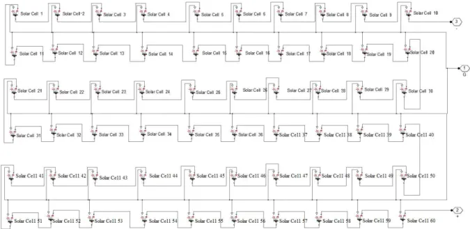
To create a SimElectronic model of one SOLIMPEKS PV module that consist of 60 cells connected in series, it is convenient to make a block diagram shown in Figure 6.
Figure 5. Dialog box and parameters simelectronics PV cell model.
Figure 6. Sixty series cells of a single SOLIMPEKS PV module.
5.3 Physical component model
Figure 7. Physical model of PV cell.
5.4 MATLAB S-Function model
With the help of MATLAB S-Function block, any model can be programmed use MATLAB instructions and added to the simulink library. The fundamental MATLAB function description algorithm code as follows:
function y = fcn(u)
% program m-file model
y = u;
where fcn: is the MATLAB function name. Here its name is defined as Icell and has been developed to calculate the current of the PV panel or system based on mathematical equations that define the PV cell. (u): is the input data (here represented G and Top)
(y): is the output data (here represented output current of PV cell).
The flowchart of S-Function model of PV system is illustrated in Figure 8.
Figure 8. Flowchart of the S-function PV system model.
6. Simulation of PV models and results
To illustrate and verify the nonlinear I-V and P-V output characteristics of PV system, all models have been tested for the SOLIMPEKS PV module under the same weather conditions of temperature and solar insolation. The specifications of the SOLIMPEKS PV module (at 1kW/m2, 25˚C) are given in Table 1. The PV system is consisting of eight modules which are connected in series as depicted in Figure 9. The whole PV system, which will be studied in this thesis, has the following specifications at STC:
- Maximum Power (Pmax) = 240 × 8 = 1920 W,
Table 1. SOLIMPEKS PV module specifications at STC (1kW/m2, 250C). Characteristics of parameters Specifications
Typical maximum power (Pmp) 240 Watt Voltage at maximum power (Vm) 30.72 Volt current at maximum power (Im) 7.81 Amp Open circuit voltage (Voc) 36.6 Volt Short circuit current (Isc) 8.36 Amp No. of cells in Module 60 cells Temp. coefficient of short circuit current 0.4*10-3 A/C0
Figure 9. Pictorial image of eight series SOLIMPEKS PV modules.
The simulation results of I-V and P-V output characteristics of PV system for all models are shown in Figure 10. All simulation results for the four models appeared almost identical to the name-plate manufacturer datasheet of the SOLIMPEKS PV module under STC.
When comparing the four MATLB models of the proposed PV system, it can be concluded the following:
i- In MATLAB S-function PV model, the connecting wires is reduced significantly, but the implemented process of the simulation slower than the other models.
ii- Simscape model is easily designed since it is ready element in Simscape toolbox. This model requires only the order of the cells in a series and parallel for the PV module after entering the required parameters in the cell element. But there are some disadvantages to this model:
1- Each PV module or system has Simscape model. In other words, there is a need to modify the model when it is used for another PV system where the cells must be re-forming to obtain the desired properties of the solar system.
2- The number of parameters that can be changed are eight as previously mentioned where some parameters are built internally. Therefore, the simulation results of this model are somewhat give lower accuracy as compared with the other models, especially in large systems.
iv-Mathematical model that develops in this study is characterized with several advantages, including: 1- Speed of execution
2- Despite the large number of connections in this model, it required only single block and does not need to overlap with another block (see Figure 4).
3- It can be applied to any PV system with any size without the need for any alteration or addition. As a result of the above conclusions, the mathematical model will be adopted to determine the PV system characteristics that contain 8 series SOLIMPEKS PV modules.
(a) I-V characteristics
(b) P-V characteristics
Figure 10. Characteristics of single SOLIMPEKS PV module for different models at STC.
7. Test mathematical model under different weather condition
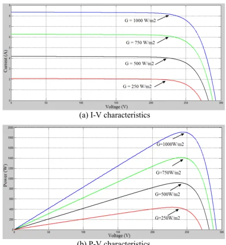
To evaluate different characteristics of SOLIMPEKS module PV system, solar insolation (G) and cell operating temperature (Top) should be changed independently to demonstrate effect degree of each parameter. Therefore, two types of simulation are carried out:
7.1 Constant temperature and varying insolation
Temperature has been kept constant at 250C and solar insolation is simulated in four levels as: 250 W/m2, 500 W/m2, 750 W/m2 and 1000 W/m2 to show the insolation dependency. I-V and P-V output characteristics of PV system under these conditions are shown in Figure 11. The results carried out under increasing solar insolation, shows that the short circuit current "Isc" increases and the power increases as well. The open-circuit voltage "Voc" is less sensible to the variation of solar insolation due to the logarithmically dependenly on it.
7.2 Constant insolation and varying temperature
(a) I-V characteristics
(b) P-V characteristics
Figure 11. Characteristics of PV system under constant temperature and varying insolation.
(a) I-V characteristics
(b) P-V characteristics
8. Conclusions
This paper provides a clear and briefly understanding of the I-V and P-V characteristics of solar PV module. It proposed a useful and accurate different MATLAB models for PV system based on one-diode model. These designed models have been verified with available SOLIMPEKS PV modules. The proposed models are used to show the effect of solar insolation and cell operating temperature on I-V and P-V output characteristics under various conditions. Also, with the help of these models, all parameters of PV system can be changed to study the effect of them on the expected behavior and output characteristics of the PV systems.
References
[1] N. Pandiarajan and R. Muthu, “Mathematical Modeling of Photovoltaic Module with Simulink”, International Conference on Electrical Energy Systems (ICEES), pp: 314-319, 2011.
[2] B. Alsayid, “Modeling and Simulation of Photovoltaic Cell/Module/Array with Two-Diode
Model”, International Journal of Computer Technology and Electronics Engineering (IJCTEE),
Volume 1, pp: 6-11, 2012.
[3] A. Gupta1 and V. U. Srinivasa, “Design, Simulation and Verification of Generalized Photovoltaic
cells Model Using First Principles Modeling”, ACEEE Int. J. on Control System and
Instrumentation, Vol. 03, No. 01, pp: 11-17, 2012.
[4] V. Singla and V. K. Garg, “Modeling of Solar Photovoltaic Module and Effect of Insolation Variation Using MATLAB/Simulink”, International Journal of Advanced Engineering Technology, Tech/IV/III, 2013.
[5] M. V. Joshi, "Mathematical Modeling and Simulation of PV System using MATLAB/Simulink", Indian Journal of Applied Research, Volume 5 , Issue 6, pp. 538-541, 2015.
[6] A. Chouder, S. Silvestre, B. Taghezouit and E. Karatepe, “Monitoring, Modelling and Simulation
of PV Systems Using LabVIEW”, Solar Energy, ELSEVIER, Volume 91, Pages 337–349, 2013. [7] J. Park et al., "Simple Modeling and Simulation of Photovoltaic Panels Using Matlab/Simulink",
Advanced Science and Technology Letters, Vol.73, pp.147-155, 2014.
[8] M. Seifi, A. Bt. Che Soh, N. I. Abd. Wahab and M. B. Hassan, “A Comparative Study of PV
Models in Matlab/Simulink”, World Academy of Science, Engineering and Technology 74, pp. 108-113, 2013.
[9] A. A. El Tayyan, “PV system behavior based on datasheet”, Journal of Electron Devices, Vol. 9, pp. 335-341, 2011.
[10] J. A. Ramos-Hernanz, J. J. Campayo, E. Zulueta, O. Barambones, U. F. Gamiz and I. Zamora, "Two Photovoltaic Cell Simulation Models in MATLAB /simulink", International Journal on TPE, Volume 4, Issue 10, pp. 45-51, 2012.
Jwad R. Mehmood , Ph.D. in Electrical Engineering, College of Engineering, Basrah University, Iraq.
Specialization: Power electronics, Graduation Date: 2006. M.Sc. In Electrical Engineering, College of Engineering/University of Basrah/Iraq. Graduation Date: 1986. B.Sc. In Electrical Engineering/ College of Engineering/University of Basrah, Iraq. Graduation Date: 1982. Teaching experience: 1- Digital electronics, 2- Electrical Machinery, 3- Advance Power electronics, 4- Computer programing, 5- Industrial automation, 6- Electric drive, 7- Renewable energy resources and 8- PLC programming. E-mail address: alali.jhana@yahoo.com
Nasir H. Selman, Ph.D. student in College of Engineering, Basrah University, Iraq. Specialization:
Electrical Power and Machine Engineering. M.Sc., University of Technology, Iraq. Specialization: Electrical Power and Machine Engineering, Graduation Date: 2005. B.Sc. In Electrical Engineering, University of Technology, Iraq. Specialization: Electrical Power and Machine, Graduation Date: 1992. Research Interests, power electronic and microcontroller.

![Figure 2. Generalized array model [4].](https://thumb-eu.123doks.com/thumbv2/123dok_br/16472641.199198/3.892.98.567.606.851/figure-generalized-array-model.webp)


