THE INFLUENCE OF VIBRATION ON
THE MILL PERFORMANCE SYSTEM
IN KOSOVO B
Ahmet LatifiDepartment of Mechanical Engineering, University of Pristine Mitrovice, Republic of Kosovo
Ismet Ibishi
Department of Mining Engineering, University of Pristine Mitrovice, Republic of Kosovo
Kadri Sejdiu
Department of Mechanical Engineering, University of Pristine Mitrovice, Republic of Kosovo
Bekim Latifi
Department of Mechanical Engineering, University of Pristine Mitrovice, Republic of Kosovo
Abstract:
In this project , briefly the work of thermo central in Kosovo B is presented especially the work of coal mill. Therefore two cases of work of these mills before and after their remount are shown and we will see how will change the settings of vibration.
Key words: electricity, produce, burning, mills, ventilation, coal.
1.The work in the Kosovo thermo centrals.
In the Kosovo Energetic Corporation the Thermo Central of Kosovo B is located which is divided into two blocks, In the block B1 and the block B2 and they serve to produce the electricity, the main source of burning is the coal which is taken from the surface mine in the’’ Bardh i mdh’’ and ‘’Mirash’’ where through the
transportation tapes comes to the thermo central and gets into the bunkers for the needs of the block. From the bunker the coal gets into the mill for grinding and after the grind gets into the boiler through the ventilator where the burning of the coal is done.
Every block has 8 mills where 7 of them must be working and one of them is the reserve, the mills are the ventilation types where they inhale the coal and after the grinding in the ventilation way and intakes of the coal into the boiler in the powder form.
2.The influence of the vibration into the mill work system.
In the thermo central of Kosovo B mills which serves for gridding coal can operate according to the production rules only 6.000 hours. After finishing of 6.000 hours the mill has to be submitted for the capital remount because the district work of mill is guaranteed to work only 6.000 hours.
Fig1. The principled scheme of the mill.
stop operating and must be taken into the capital remount because of achieving 6.000 hours, so this tolerance is created between the axle and bearings of bearing.
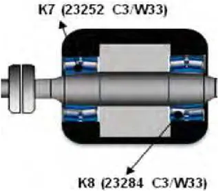
Fig2 .Created vibrations to the double bearing to the bearing K7 and K8.
High vibrations to the mill, can cause some further serious problems in the mill if it doesn’t stop operating and those damages can be as following ;
* The damage of bearings to the electromotor, adapter and the district work (working circuit). * The damage of the electromotor rotor of axle, adapter and the district work (working circuit). * The damage of the basement of electromotor, hydraulic triangle (coupling) ,adapter, the double bearing etc.
Condition of the mill M2 vibrations of the block B1 is shown and appeared to the below scheme.
Fig. 3 – The scheme of mill vibrations M2 to the block B1.
Below they are given the measuring tables of the mill vibrations where after the measuring vibrations and a conclusion has been given , it shows that the mill has only two horizontal vibrations where those vibrations are given with the red color, according to the legend this mill must not be allowed for a further operation with such vibration parameters because it can cause other series damages which were mentioned earlier.
4. Appearance of the tables of vibrations before remount
Tab1. -Appearance of vibrations of the mill M2 in B1.
The legend of this table is given with colors and it is as follows:
Standard recommendation of the vibrations ISO 10816-3 PEM=300kW-50MW is:
Zone C and D are given to the coming up schemes:
After finishing of measuring vibrations and advice warning has been issued for the mill situation from the survey team and the examination of vibration measuring and for this mill summaries are as below:
Warning: The vibration from all measuring points to the horizontal direction of this machine is out of the allowed limit for operation. It is recommended immediate division of this machine. Indications of rising of these vibrations are as a result of mechanic lacks in the double bearing K7 and K8. It is possible that a tolerance between the axle and the rolling bearing K8 have been occurred.
After conclusion of the capital remount from the pipeline team of the mill where the primary work was the change of bearing of the double bearing and the axle of these bearing so the other works of remount from the mechanic pipeline of this mill are:
*The verification of electromotor bearing if they are damaged or not, if they are damaged they must be replaced or changed and lubricate the bearing.
*The verification of the triangle axle bearing if there were any damage and verification of bearing pump if there is enough pressure and also the change of oil if it is necessary or just to refill the oil level.
*The verification of oil pressure to the electronic pump of the bearing, the cleaning of the oil filter and the change of oil if it is needed or refilling the oil level.
*The verification or the exchange of the adapter bearing and regulation of the oil pressure to the mechanic pump of the adapter and qualifying the adapter’s electronic pump and the regulation of pressure in this pump, cleaning of these oil filters and exchanging the oil if it is needed or refilling of oil level as well, the verification of the adapter axels if they are damaged they have to be exchanged according to the requires.
*The verification of the mechanic triangle in the middle of the adapter and the double bearing if they are damaged the linking tailor and the oiling of this mechanic triangle.
*The verification of bearings where to this mill they have been exchanged and the axle of the double bearing, regulation of the mechanic pump and the electronic pump, the cleaning of the oil filters and the verification of the oil tube or the connections between tubes if there is any oil leak the exchange of the oil if it is necessary or Mill M2 of the block B1
the date of measuring on vibrations
Speed vibration
RMS
K1 K2 K3 K4 K5 K6 K7 K8 Vef (mm/s) Vef (mm/s) Vef (mm/s) Vef (mm/s) Vef (mm/s) Vef (mm/s) Vef (mm/s) Vef (mm/s) Mill M2 The position of measuring vibrations
Vertical 6.53 6.66 2.46 4.49 4.20 3.11 6.63 9.14
Horizontal 20.89 20.36 18.43 19.31 19.45 19.50 18.19 19.88
*Cleaning of the mill separator.
Hydraulic triangle (coupling) , and the précising the hydraulic triangle with adapter, précising of the adapter with a double bearing through the mechanic triangle is the précis of the double bearing through the mechanic triangle and the précising of the double bearing to the district work of this mill.
Where after the concession of the mill to work there is called the examining team and measuring vibrations to the situation of the mill M2 vibrations were as following:
5. The appearance of vibrations after remount
Tab.2- the values of the vibration parameters after remount to the mill.
So after conclusion of this mill remount the basic changes of the mill work and the rising temperature in area are noticed and it has been found out that it grinds and work better, so according to the measure of vibrations all the mill bearings are to the limited area vibrating.
In the next diagram there are given parameters of the nr.2 mill, after a long time being on work operation where in this diagram there can be seen:
*Temperature of the mill *Mill loads
* Coal tonnage for the mill * Leak of the coldness gas
* Leak of the primary and secondary air * Temperature of the first and seconds air and *Block load in MW
Tab.3- Value of the following diagram
Name Nomenclature Value Unit
Mill temperature NL42 T100 169. °C
Coal tonnage for the mill NL 16 Y002 60 t/h
The number of rotations to the given coal NL16 S002 3.5 RPM
Appearance of the mill cooling gas NS16 S001 30 %
Leaking air for burning(for the coal ignite) NG18 F001 141 kNm3/h
Temperature of the hot air for burning(for the
coal ignite) NG18 T001 250 °C
Block load 1JE20C321 236.33 MW
Mill M2 of the block B1 the date of measuring on
vibrations
Speed vibration
RMS
K1 K2 K3 K4 K5 K6 K7 K8 Vef (mm/s) Vef (mm/s) Vef (mm/s) Vef (mm/s) Vef (mm/s) Vef (mm/s) Vef (mm/s) Vef (mm/s) Mill M2 The position of measuring vibrations
Vertical 1.25 1.22 1.86 2.15 1.35 1.35 1.13 1.23
Horizontal 1.22 3.22 1.15 1.75 1.66 1.95 2.22 1.61
Axial 3.12 1.06 0.98 1.22 0.55 1.86 1.19 1.22
Fig.4. Parameters diagram of the mill nr.2 after a long operation CONCLUSION
According to the rule, vibrations will be measured in each: Once a month
Three months Six months Once a year
After vibrating measurement we also have to qualify the values of these measures and there will be analysis to see how it came to the vibrations and the damages that can become during these vibrations.
Reference:
[1] Branislav Jeremic: Teretehnologija Mashinski fakultet Kragujevac, 2007 [2] Ivo Coler: Odrzavanje elektrana, Zagreb
[3] Jeton Fejza: Udhezime per mirembajtje, Prishtine, 2002 [4] Ivo Cola: Zadaci I funksije odrzavanja, Zagreb