Journal of Applied Fluid Mechanics, Vol. 8, No. 1, pp. 75-84, 2015.
Available online at www.jafmonline.net, ISSN 1735-3572, EISSN 1735-3645.
Experimental Investigation of the Effect of Spacing between
Vertical Plates on the Development of a Thermal
Plume from an Active Block
T. Naffouti
1,2†, J. Zinoubi
1,3and R. B. Maad
11
Université Tunis El-Manar, Faculté des Sciences de Tunis, Département de Physique,
Laboratoire d’Energétique et des Transferts Thermique et Massique, El Manar 2092, Tunis, Tunisia.
2 Université de Carthage, Institut Préparatoire aux Etudes d’Ingénieurs de Nabeul, Campus Universitaire Merezka- 8000, Nabeul, Tunisia.
3Université Tunis El-Manar, Institut Préparatoire aux Etudes d’Ingénieurs El-Manar, El-Manar 2092, Tunis, Tunisia.
†Corresponding Author Email: [email protected]
(Received December 24, 2013; accepted February 23, 2014)
ABSTRACT
In this paper, an experimental investigation was conducted to analyze the effect of spacing between vertical plates of a parallelepipedic canal on the average thermal and dynamic fields of a thermal plume. To carry out this study, we placed at the laboratory a rectangular heat block at the entry of a vertical canal open at the ends. The internal walls of the plates are heated uniformly by Joule effect and by thermal radiation emitted by active source. The heating of walls creates a thermosiphon flow which interacts with the plume inside canal. Four dimensionless spacing between the plates 1.25 ≤ e* ≤ 30 are considered. It is found that the spacing is the most important geometrical parameter affecting the thermal and dynamical behavior of the flow. Using visualization by laser plan and hot wire probe, flow structure evolves in two zones for smallest and largest spacing while a supplementary zone near heat source is observed for an intermediate spacing. The variation of flow rate and energy transported by the fluid shows the existence of an optimum spacing where the propagation of plume flow is more accelerated.
Keywords: Natural convection, Heat block, Thermal plume, Thermosiphon flow, Optimum spacing.
NOMENCLATURE
b1 source width
D f sensitive wire diameter e spacing between canal walls
e* dimensionless spacing between canal
plane plates, ( 1 *
b e
e )
g gravitational acceleration Gr grashof number,
(
3 1 2 ( s a)
g T T b
Gr
)
E* dimensionless energy absorbed by the fluid
by unit of width, ( E*
U*T*dX*)L 2 height of the canal L 1 length of the source (x,y,z) cartesian coordinates
X* dimensionless coordinate, ( 1 *
b x
X )
Z* dimensionless height, (
2 *
L z
Z )
L 2 length of the canal L f length of the sensitive wire
Q v* dimensionless flow rate by unit of width,
(Qv*
U*dX*)T average temperature
T a temperature of the ambient air T s temperature of hot source T* dimensionless temperature,
(
a s
a
T T
T T T
* )
U vertical average component velocity of the flow
U ref reference velocity,
(Uref g(TsTa)b1)
thermal expansion coefficient76 1. INTRODUCTION
Thermal plumes behavior from a heated block is an interesting subject of study from both theoretical and practical points of view. This natural convection flow which interacts with neighbouring materials is observed in nature and in industrial environment such as fire declared in forests/tunnels, heating of buildings and heat exchanger (Jolly and Saito, 1992; McGrattan et al., 1996; Shiraishi et al. , 1999; Hara and Kato, 2004; Vauquelin and Telle, 2005; Lavrov et al., 2006; Mahmoud et al., 2008; Wang et al.,2009; Wen and Lian,2009; Shi et al., 2009; Pu et al., 2011; Wang et al., 2011; Jafari et al.,2011; Most and J.B. Saulnier, 2011). In order to improve the techniques of prevention and to control the fires and the atmospheric pollutions, many researchers have focused their attention on thermal plumes flows.
Nakagome (1976) performed an experimental investigation of thermal plume produced by a heat spherical calotte. He noted that the flow structure is divided in two different zones. By studying thermal plume behavior with hot jet, George et al. (1977) found that the average dynamic and thermal profiles are similar far from heat source. Then, Yang (1992) examined the deformation of thermal plume from planar heat source/Cigarette smoke. The transition zone of plume between laminar and turbulent flows is characterized by a dissymmetrical deformation of the flow. An experimental study of thermal plume with hot disc is conducted by Mahmoud (1998). He found that the flow structure is divided in two different zones and the energy absorbed by the fluid remains constant and the flow rate increases as we move away from the heat disc. After two years, Pretot et al. (2000) experimentally and numerically investigated the natural convection flow above a hot horizontal plate placed in a semi infinite medium. He noted the existence of two flow regions identical to a thermal plume. By, studying the development of two thermal plumes generated by a hot disc and a hot vertical cylinder, Bouzinaoui (2007) show that the plume enthalpy is conserved and the flow rate increases vs altitude z. After, Naffouti et al. (2010) characterized a thermal plume produced by a hot rectangular source. Visualization as well as thermal and dynamic fields shows that the global structure of the flow is divided into two zones. Near the hot source, a first zone of plume development. Higher, a second zone of transversal expansion of the plume is found.
Technical literature presents a great number of studies on the interaction phenomenon of thermal plumes through experimental investigation. By examining the interaction between hot jets, N.E.Kotsovinos (1976) found that the dynamic and thermal profiles of cold jets and thermal plumes are different. After, Agator (1983) studied the interaction of a thermal plume with a vertical wall. He shows that the global flow structure is identical to classical zones of free plume and the plume axis is deviated towards the wall. At that time, Brahimi (1989) studied the interaction between identical plumes from two hot discs. Total interference of two plumes is observed. By studying the interaction of thermal plumes
generated by two hot sections placed on a horizontal plate, Ichimiya (2005) noted the existence of three flow models.
Inside a medium delimited by vertical walls, the plume emits a thermal radiation to vertical walls. This heating causes the appearance of a thermosiphon flow which interacts with the thermal plume. Mahmoud (1998) is the first which studied the interaction between thermal plume and thermosiphon in a vertical cylinder open at the ends. He noticed the appearance of a supplementary zone which is added to classical zones of free plume. This zone is characterized by the formation of symmetrical contrarotating rollers on both side of plume axis. Compared to a free plume, he noted an intensification of thermal transfer and an increase of average flow rate. A little later, Zinoubi (2004) examined the influence of form parameters on resulting flow plume-thermosiphon. The results demonstrated an increasing of average flow rate for a reduction of spacing source-cylinder. At same time, Bouslimi (2005) studied a guided thermal plume evolving inside a vertical cylinder open at the ends. He noted that the structure flow is divided in two zones. During this time, Zinoubi (2007) studied a thermal plume with heat disc inside a vertical parallelepipedic canal. The effect of form parameters on thermal and dynamic qualities of solar hot-air generator is presented by Mahmoud (2007). He found that the heat flux absorbed by the air and the flow rate increase for a reduction of spacing source-cylinder. After, Naffouti et al (2009) examined a thermal plume with rectangular heat source inside a vertical canal. The results of this study show that the thermosiphon intervenes to limit the expansion of the plume, activates the ascending flow and quickly homogenizes the fluid at the exit of the system. Then, Naffouti et al (2010) characterized a thermal plume in interaction with its material environment. They noted that the confinement effect causes an increase of flow rate and an intensification of thermal transfer. After, Zinoubi (2011) analyzed the Temperature Spectra from a Turbulent Free Thermal Plume and in Interaction with its Material Environment.
It was found from the available literature that not much work has been done about the effect of spacing between vertical planes walls of a parallelepipedic canal on thermal plume behavior. At the laboratory, a rectangular block heated at the upper horizontal wall is localized at the entry of the canal. The main objective of this work is to analyze the spacing effect of canal on the flow development in order to enhancing our understanding of physical mechanisms of thermal plumes.
2. EXPERIMENTAL APPARATUS AND
METHODS USED
2.1 Materials and Methods
77
Fig. 1. Experimental device used
electrically heated at a uniform temperature of 573 K. This heat source is placed at the entry of a vertical canal (2). The canal is composed by two Duralumin parallels square plane plates and two other rectangular Plexiglas plates to close the canal. The canal has a height of L2 = 40 cm and a variable spacing e ranging from 7.5 cm to 180 cm. In this connection, spacing variation between the two Duralumin plates is the base of this study. The device is placed on a frame (3) at 80 cm above the ground to allow air supply from below.
The Uniformity of the temperature of the surface is obtained by the wire resistors mounted behind this one. The temperature of source is measured by three Al-Cr thermocouples placed at the middle and at the ends. A thermal regulation apparatus keeps the surface temperature as uniform as possible within a good approximation. The temperature difference between the ends and the middle is less than 1%. In order to reduce the heat losses from below and minimise the temperature variation of the ambient air, this source is insulated at this side. The two Duralumin plates of the canal are maintained at a constant temperature of 323 K. The internal walls of the plates are heated by Joule effect and thermal radiation emitted by the source of the plume. The electric heating of plates is carried out by carbon paper resistance of thickness 0.5 mm. The temperature distribution of these walls is measured by nine Al-Cr thermocouples introduced by the back face of each plate. In addition, the two plates are insulated at the back by the superposition of several layers of insulating materials (Kerlane). The strong dependence of flow on surrounding conditions requires conducting the experiment in a quiet
atmosphere. So, experimental apparatus is placed in an independent closed cubical room of side 4 m. In order to check the thermal stability of ambient air, several thermocouples are fixed at different heights in the room.
To explore thermal and dynamic average fields inside the canal, a resistant wire anemometer (4) at constant current is used (CCA). A calibration of the probe wire carried out in our laboratory allows the determination of the temperature and the velocity of the flow from the voltage across the probe (Brahimi et al., 1989; Zinoubi et al., 2004). This method adopted for a long time by, in natural convection, is based on the resistance variation of the sensitive wire according to the temperature and velocity when it is supplied by a constant current. The sensitive platinum wire of the probe has a diameter of Df = 7.5 µm and a length of Lf = 3 mm. In order to avoid the disturbance of the flow, probe is introduced vertically through the system exit, so that its sensitive wire is perpendicular to the ascending average flow. Errors due to the probe calibration are lower than 1 %. A probe displacement system (6) in the x and z directions, is used to explore the thermal field inside the canal. The minimal displacement in the vertical direction is 1 mm, whereas in the horizontal direction it is 0.20 mm. On the other hand, a computer provided with a data acquisition card permits to take the instantaneous measurements of temperature and velocity and to record signals for further statistical processing (5, 7, 8). In application of the Shannon theorem, the period of sampling of 15 ms was chosen. The measurements of thermal field are carried out by cold wire anemometer supplied by a current of 1.2 mA instead of using thermocouples. Indeed, time constant of the sensitive wire is 1 ms and that of thermocouple of 25
m
in diameter is 50 ms. In addition, thermal inertia of the probe does not introduce any measurement errors especially at the low frequencies found in thermal plume (Son et al., 1975). The hot wire anemometer is used to measure the local velocity of the flow. In this case the probe is supplied by a current of 50 mA which makes it sensitive simultaneously to temperature and velocity.2.2 VISUALIZATION PROCESS
78
Fig. 2. Visualization system of the flow
3. EXPERIMENTAL RESULTS AND DISCUSSIONS
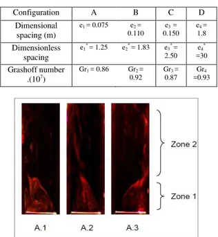
The experimental results are carried out with air (Pr = 0.71) inside the canal. Table.1 illustrates four study configurations with variation of spacing e* between vertical plates of the canal. The configuration; A, B, C and D are related to spacings; e1= 7.5 cm, e2= 11 cm, e3= 15 cm and e4= 180 cm, respectively. In regard to the largest spacing, configuration D is identical to a thermal plume evolving in free and unlimited medium. In this case, thermosiphon flow is not present and consequently interaction between thermal plume and this one is neglected. In the present study, three sections for each configuration are presented (Fig.3). An intermediate section Z* = 0.37 and two sections localized at the entry Z* = 0.10 and at the exit of canal Z* = 0.92.
3.1 Flow Visualization
By video recordings of the visualization, we have chooses instantaneous photos on the vertical mid-plane of the canal (xoz) to describe qualitatively the global structure of the flow.
3.1.1 General View of the Flow for Configuration A
Fig.3 illustrates the evolution of the flow on the plane (xoz) for spacing e1 = 7.5 cm (configuration A). This qualitative description shows that the global flow structure is divided in two zones distinct from those of free plume. In the first zone near the hot block, it is found that the presence of trapped threads on both sides of heat source and consequently the system is supplied in fresh air by the low. At the sides of source, Fig 3.A.1 and Fig 3.A.3 show that the fluid aspiration does not have same behavior. In this connection, we noticed the existence of a certain alternation between formation and exhaust of the vortexes. When plume source is supplied by one side, trapped fluid of the other side continues its
Table 1 Spacing variation between vertical walls
Fig. 3. Flow visualization: configuration A
path along the canal wall. After, these two threads shape an envelope which is attracted by the wall. This envelope obliges the fresh air coming from the system low to supply the plume by the top. The fluid in contact of source finds a difficulty to escaping. Thus, it continues to turn on itself to escape vertically (Fig 3.A.1). To replace this released fluid, this region is supplied again with fresh air. In the second zone at the higher part of canal, visualization shows the blocking of ascending flow. This result is observed by Zinoubi (2004, 2007) on thermal plume evolving inside a vertical cylinder.
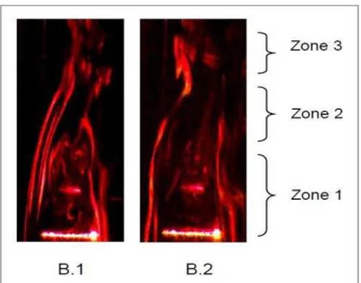
3.1.2 General View of the Flow for Configuration B
The present work shows that the spacing of walls affects the flow structure by increasing this geometrical parameter. Compared to configuration A, flow structure on the plane (xoz) is divided in three zones (Fig. 4). Just above the hot source, a first zone where the plume is enveloped by the thermosiphon flow. The fluid aspired on both side of generating source is divided in two trapped threads which undergo at the start an attraction by the plume before carrying on their way along the canal wall. A little more downstream from the source, a second zone is characterized by a weak contraction of the resulting flow. In the higher par of canal, a third zone of no homogenization of the flow is observed.
3.1.3 General View of the Flow for Configuration C
Concerning the third configuration whose spacing e3 is 15 cm, Fig.5 shows the existence of three zones comparable with those of configuration B. Close to heat source, a first zone where the flow development is strongly influenced by the source causing a feeding of the system by the low in fresh air divided in three trapped threads. The first threads on both sides of the source edges are directed towards the central region of the flow to shape an envelope above hot source. This
Configuration A B C D Dimensional
spacing (m)
e1= 0.075 e2=
0.110 e3 =
0.150 e4=
1.8
Dimensionless spacing
e1* = 1.25 e2* = 1.83 e3* =
2.50 e4*
=30
Grashoff number .(107)
Gr1 = 0.86 Gr2 =
0.92
Gr3 =
0.87 Gr4
79
Fig. 4. Flow visualization: configuration B
Fig. 5. Flow visualization: configuration C
Fig. 6. Flow visualization: configuration D
impenetrable envelope at source sides obliges the fresh air to be introduced by its top. The second thread relatively near to canal wall is entirely influenced by the formation-exhaust cycle of the vortexes. The intermediate thread which constitutes a provision source in fresh air for the flow pursues its way directly towards the central part of the flow. Higher of the source, a second zone is characterized by a contraction of the ascending flow. At exit of canal, a third zone where the flow widens towards the walls.
3.1.4 General View of the Flow for Configuration D
Fig.6 corresponding to configuration D demonstrates the strong effect of largest spacing on the behavior of
the flow. Global structure of the flow on the plane (xoz) is subdivided in two zones identical to free plume. Just above the generating source, a first zone of flow development where this one is supplied in fresh air by the low and by the sides. The trapped fluids directed towards the source surface are entrained temporarily by ascending flow of plume. In the higher of heat source, figure shows a second zone of transverse expansion of plume towards the canal walls.
3.2 Average Thermal Field
3.2.1 Isotherm of the flow
The isotherms networks of the dimensionless average temperature of the flowfor four spacings are showed in Fig.7. This representation traced in a vertical transverse mid-plan (xoz) confirms the strong influence of the spacing on thermal field of the flow between canal walls.
Fig.7.A corresponding to spacing 7.5 cm show the existence of two zones described previously by the visualization. The first zone, near hot source, is characterized by intense thermal gradients. The high values of temperature are owing to a transformation of ambient air at the plume. In the second zone higher heat source, the temperature increases as we move away from the source. Increasing the spacing to 11 cm (configuration B), Fig.7.B consolidates the existence of three zones demonstrate before. Just above hot source, a first zone is defined by strong thermal gradients owing to predominance of thermal plume. On both sides of source, weak temperatures prove the feeding of the system by the low. A little higher, a second zone is characterized by weak temperatures in central part caused by the penetration of fresh air to supply the plume. In this zone, we note a light increase of the temperature as we move away from the canal walls. In the higher part of canal, a third zone where the temperatures are uniform.
80
Fig. 7. Iso-values of the dimensionless average temperature of the flow for configurations
A, B, C and D
3.2.2 Transversal evolution of the average
temperature
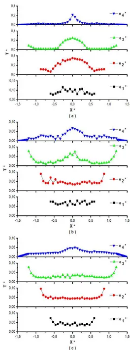
Fig.8 depicts the transverse distribution of the dimensionless average temperature of the flow for three sections versus the spacing. The corresponding profiles consolidate the influence of spacing between the walls on the flow temperature. In the level close to heat source Z* = 0.10 (Fig 8.a), plot corresponding to smallest spacing e1* shows a light variation of thermal gradient. This indicates that the temperature is practically uniform above hot source. When spacing e* increases, profile becomes more narrowed and the maximum of temperature is located on median plan of the source (yoz). In the vicinity of this plan, we note high thermal gradients translating the preponderance of thermal plume. For spacing e3*, temperature is very weak on both sides of source due to the preponderance of the fresh air which comes to supply the system. Fig.8.b relating to intermediate level Z* = 0.37 shows an attenuation of the temperature and a flatness of profiles for a reduction of spacing. Near canal walls, temperature increase owing to the heating of these latest by Joule effect and by thermal radiation emitted by the heat source. In higher level Z* = 0.92, Fig.8.c shows a flatness of thermal plots except for largest spacing e4* This indicates the uniformity of temperature in the central region of the flow at canal exit.
Fig. 8. Transversal distribution of the dimensionless average temperature of the flow vs spacings e* for
three sections (a): Z*=0.10, (b): Z*=0.37, (c): Z*=0.92
3.3 Average dynamic field
3.3.1 Iso-values of the velocity of the flow
Fig.9 illustrates the iso-values of the dimensionless vertical average component velocity of the flow for different spacings. It is found that the dynamic behavior of the flow is affected by increasing the spacing of canal walls.
81
Fig. 9. Iso-values of dimensionless vertical average component velocity of the flow for
configurations A, B, C and D
space between source and canal walls, the flow is decelerated due to the dominance of charge losses. Indeed, source of plume is similar to an obstacle which slows the flow ascension at the system entry. We note that this phenomenon is noted by Ben Maad (1992). Downstream of the source, a second zone is characterized by weak dynamic gradients thus indicates the homogenization of the velocity in the superior part of canal. For configuration D where the spacing is largest (Fig.9.D), figure consolidates the existence of two zones different to configuration A. Near hot source, a first zone where the flow is accelerated due to entrainment of fresh air by the plume. While moving away from source and from median plane (yoz), flow velocity is attenuated in second zone due to transverse expansion of the plume. In this configuration, we note the absence of two phenomena of thermosiphon and charges losses. Compared to configurations A and D, we note the appearance of a supplementary zone in configuration B owing to thermosiphon effect (Fig.9.B). In the first zone any meadows of hot source, we notice strong velocities at the source sides. This is caused by an intensification of the thermosiphon and by the decrease of charges losses. In the central part above the source, the velocities are weak what translates the existence of weak circulation of flow inside the envelope. A little higher of the hot source, second zone is characterized by a light contraction of the resulting flow. In the vicinity of median plan (yoz),
flow contraction causes an increase of velocities. As moving away from hot source, trapped threads exist even in third zone on both sides of the median plan (yoz).
Fig.9 relating to configuration C confirms the evolution of the flow in three zones announced previously. Compared to configuration B (Fig.9.B), thermosiphon becomes more intense and its interaction with the plume is stronger. In the first zone close to heat source, the flow is more accelerated on both sides of the heat source owing to the presence of threads fluid which supplies the system by the low. Downstream in intermediate zone, resulting flow is more contracted and dynamic gradients are more significant around the median plan (yoz). These results are due to vortexes exhaust announced by the visualization. In the higher zone, the velocity is practically constant what indicates the homogenization of the flow.
3.3.2 Transversal Evolution of the Average Velocity
Fig.10 presents the transverse distribution of the vertical component dimensionless average velocity of the flow for three sections versus spacing e*. On the level near to the hot source Z* = 0.10, Fig.10.a shows a comparable velocities for spacing e1*. In intermediate space between heat source and canal walls, velocity is weaker due to the charges losses. For the plots relating to the spacing e2* and e3*, figure shows an intensification of the dynamic gradients on both sides of the source owing to the important effect of thermosiphon which accelerates the ascending flow. In the vicinity of the median plan (yoz), minimum of velocity proves the existence of a weak circulation region. For largest spacing e4*, the flow is accelerated only in the central region above heat source. In section Z* = 0.37, Fig.10.b shows an attenuation of velocity for all spacings except spacing e4*. In level Z* = 0.92 (Fig.10.c), the velocity is more uniform for spacings e1* and e3*. This indicates a homogenization of the flow at canal exit. For spacing e4*, velocity profile is more widened due to the expansion of the plume.
3.4 Flow Rate and Energy Absorbed by the Fluid
3.4.1 Vertical Evolution
82
Fig. 10. Transversal distribution of the dimensionless vertical average component velocity of the flow versus spacings e* for three sections, (a):
Z*=0.10, (b): Z*=0.37, (c): Z*=0.92.
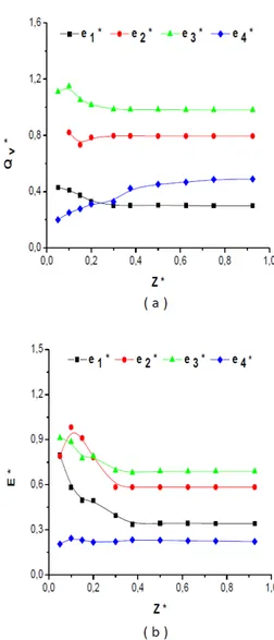
rate increases with altitude Z* (Fig.11.a). This is owing to the entrainment of ambient air by the ascending flow of the plume. Compared to configurations A and D, it is found an improvement of flow rate about 30 % in particular for configuration C owing to the important effect of the thermosiphon which accelerates the ascending flow. In regard to the energy E* (Fig.11.b), this parameter is conserved for high altitudes Z*. The energy increases to reach a higher value for spacing e3 = 15 cm after it decreases by 30% versus spacing. The intensification of energy extracted from source and canal walls is caused by the strong effect of the thermosiphon which favors the transport of energy between particles during the ascension of the flow.
Fig. 11. Evolution of the dimensionless flow rate Qv* and the dimensionless energy transported
by the fluid E* vs altitude Z* for different spacings e*
3.4.2 Determination of the Optimum Spacing
83
Fig. 12. Variation of the dimensionless flow rate Qv*
(a) and the dimensionless energy transported by the fluid E* (b) versus spacings e*
3. CONCLUSION
The present work reports an experimental study of the effect of spacing between verticals planes plates on the average thermal and dynamic fields of the thermal plume. This natural convection flow is generated by a heat rectangular block placed at the entry of a vertical parallelepipedic canal open at the ends.
The following conclusions can be drawn from the results obtained from this investigation:
- It is found that spacing of walls is the most important parameter affecting thermal and dynamic behavior of thermal plume inside canal. For smallest spacing, the global flow structure is divided in two zones which are different from those of free thermal plume. Just above the heat source, à first zone of the preponderance of charges losses phenomenon which slows down the ascending flow at canal entry. Downstream from heat source, a second zone characterized by a partial blocking of ascending flow. Increasing of spacing causes an appearance of a supplementary zone near the heater characterized by an impenetrable envelope. This behavior changes completely in a second zone where the flow is contracted. In higher part of canal, a third zone of flow homogenization owing to the thermosiphon which activates the development of ascending flow. For largest spacing, flow structure becomes identical to free thermal plume.
- It is observed the existence of an optimum spacing whose flow rate and thermal energy are maxima due to strong effect of thermosiphon which favors the transport of energy between fluid particles. - As we reduce the spacing, flow rate and thermal
energy decrease owing to the preponderance of charges losses over thermosiphon flow.
- For spacings greater than optimum spacing, thermal transfer and flow velocity are attenuated due to a weakening of thermosiphon effect.
The present analysis can enables to advance our understanding of the physical phenomena governing the development of thermal plumes in order to improve the safety techniques of the environments and to control the fluid flow (fires/pollution/thermal systems…). In the future works, next attention is focused on the spacing effect of the canal on turbulent characteristic of the thermal plume.
REFERENCES
Jolly, S. and K. Saito (1992). Scale Modeling of Fires with Emphasis on Room Flashover Phenomenon. Fire Safety Journal. (18), 139-182.
McGrattan, K.B., H.R. Baum and R.G. Rehm (1996). Numerical simulation of smoke plumes from large oil fires. Atmospheric Environment. (30) 4125-4136.
Shiraishi, Y., S.Kato, S.Murakami, S.Kim and R.Ooka (1999). Numerical analysis of thermal plume caused by large-scale fire in urban area. Journal of Wind Engineering & Industrial Aerodynamics. (81) 261-271.
Hara, T., and S.Kato (2004). Numerical simulation of thermal plumes in free space using the standard k– ε model, Fire Safety Journal. (39) 105-129.
Vauquelin, O., and D.Telle (2005). Definition and experimental evaluation of the smoke ‘‘confinement velocity’’ in tunnel fires. Fire Safety Journal. (40), 320–330.
Lavrov, A., A.Utkin, R.Vilar and A.Fernandes (2006). Evaluation of smoke dispersion from forest fire plumes using lidar experiments and modelling, International Journal of Thermal Sciences. (45), 848-859.
Mahmoud, A. O.M., J. Bouslimi and R. Ben Maad (2008). Experimental study of the effects of a thermal plume entrainment mode on the flow structure: Application to fire, Fire Safety Journal. (44), 475-486.
Wang, Y., J. Jiang and D. Zhu (2009). Full-scale experiment research and theoretical study for fires in tunnels with roof openings, Fire Safety Journal. (44), 339–348.
84 Shi, C.L., M.H. Zhong, T.R. Fu, L. He and R. Huo
(2009), An investigation on spill plume temperature of large space building fires, Journal of Loss Prevention in the Process Industries. (22), 76-85.
Pu, L., C.Ai-ping and W.Chao (2011). Study on Fire Plume in Large Spaces Using Ground Heating, Processes Engineering. (11), 226-232.
Wang, Y., P.Chatterjee and J. L. de Ris (2011). Large eddy simulation of fire plumes, Proceedings of the Combustion Institute. (33), 2473-2480.
Jafari, M., J. A. Karimi, A.E. Usachov and H. Kanani Moghaddam (2011), The Fire Simulation in a Road Tunnel, Journal of Applied Fluid Mechanics. (4), 121-138.
Most, J.M., and J.B. Saulnier (2011), Under-Ventilated Wall Fire Behaviour during the Post-Flashover Period, Journal of Applied Fluid Mechanics. (4), 129-135.
Nakagome, H., M. Hirata (1976). The structure of turbulent diffusion in an axisymmetric thermal plume, Proc. Int Semtur Buoyancy Convection. 361-372.
George, W.K., R.L. Albert, F. Tamanini (1977). Turbulence measurements in an axisymmetric buoyant plume, International Journal of Heat and Mass Transfer. (20), 1145-1154.
Yang, H.Q. (1992). Buckling of a thermal plume, International Journal of Heat and Mass Transfer. (35), 1527–1532.
Mahmoud, A.O.M., R. B. Maad and A. Belghith (1998). Interaction d’un écoulement de thermosiphon avec un panache thermique à symétrie axiale : étude expérimentale, Revue Géneral de Thermique. (37) 385-396.
Pretot, S., B.Zeghmati and G.Le.Palec (2000), Theoretical and experimental study of natural convection on a horizontal plate, Applied Thermal Engineering. (20), 873–891.
Bouzinaoui, A., R. Devienne, J.R. Fontaine (2007). An experimental study of the thermal plume developed above a finite cylindrical heat source to validate the point source model, Experimental Thermal Fluid Science. (31), 649–659.
Naffouti,T., J. Zinoubi, R. Ben Maad (2010). Experimental characterization of a free thermal plume and in interaction with its material environment, Applied Thermal Engineering. (30), 1632-1643.
Kotsovinos, N.E. (1976). A Study of the interaction of turbulence and buoyancy in a plane vertical buoyant jet, Proc. Int. Semtur.Buoyancy.Convection. 15-26.
Agator, J.M. (1983). Contribution à l’étude de la structure turbulente d’un panache thermique à symétrie axiale. Interaction du panache avec son environnement limité, Thèse de Docteur-Ingénieur, Université de Poitiers.
Brahimi, M., L.Dehmani and D.K.Son (1989). Structure turbulente de écoulement d’interaction de deux panaches thermiques, International Journal of Heat and Mass Transfer. (32), 1551-1559.
Ichimiya, K. and H. Saiki (2005). Behavior of thermal plumes from two-heat sources in an enclosure, International Journal of Heat and Mass Transfer. (48), 3461–3468.
Zinoubi, J., R. B. Maad and A. Belghith (2004). Influence of the vertical source-cylinder spacing on the interaction of thermal plume with a thermosiphon flow: an experimental study, Experimental Thermal Fluid Science. (28) 329-336.
Zinoubi, J., R. B. Maad, A. Belghith (2004). Experimental study of the resulting flow of plume-thermosiphon interaction: application to chimney problems, Applied Thermal Engineering. (25), 533-544.
Bouslimi, J. and L.Dehmani (2005). Experimental investigation of the thermal field of a turbulent plume guided by a cylinder-preliminary results, Experimental Thermal Fluid Science. (29), 477–484.
Zinoubi, J., A. Gammoudi, T. Naffouti, R. Ben Maad and Ali Belghith (2007). Developpement of an Axisymmmetric Thermal Plume between Vertical Plates, American Journal of Applied Sciences. (4), 679-685.
Mahmoud, A.O.M., J.Zinoubi and Rejeb Ben Maad (2007). Study of hot air generator with quasi-uniform temperature using concentrated solar radiation: Influence of the shape parameters, Renewable Energy. (32), 351–364.
Naffouti, T., M. Hammami, M. Rebay, and R.B. Maad (2009). Experimental Study of a Thermal Plume Evolving in a Confined Environment: Application to Fires Problems, Journal of Applied Fluid Mechanics. (2) 29-38.
Zinoubi, J., T. Naffouti and R.B. Maad (2011). Temperature Spectra from a Turbulent Free Thermal Plume and in Interaction with its Material Environment, Journal of Applied Fluid Mechanics, (4), pp. 69-76.
Son, D. K., M. Stage and J.Coutanceau (1975). Transfert de chaleur entre un fil anémométrique court et un écoulement à faible vitesse. Revue Géneral de Thermique. N°168.