in
Produc t ion Engine e ring
2013, No 3 (11), pp 9‐13
Abstract:
‘Shore to ship’ system – ships’ power supply from the local electrical substa ons – is one of the effec ve ways to limit the nega ve impact of the ships lying in ports on the environment. Energy infrastructure of the port installa on necessa‐ ry to provide ships with power supply has to be designed so that different types of ships can use it.
The important issue concerning ‘shore to ship’ system is the quality of power supply. This can be achieved via sustaining con nuity of power supply while switching from the ships’ electrical network over to the na onal grid.
In this ar cle the author presents the way of synchronizing the na onal grid with the ships’ electrical network during
ship’s lying in port. Such synchroniza on would allow for uninterrup ble work of the ship’s electrical devices.
SYNCHRONIZATION
OF
NATIONAL
GRID
NETWORK
WITH
THE
ELECTRICITY
SHIPS
NETWORK
IN
THE
"SHORE
TO
SHIP"
SYSTEM
INTRODUCTION
Ships are like floa ng businesses. Produc on and distri‐ bu on of power is performed in the environment in which obtaining power from the external sources is impossible. Ships’ electrical installa ons are indispensible for the main motor opera on, naviga on, communica on, as well as for the suppor ng systems that provide basic facili es such as ligh ng, water supply systems and hotel services.
In the majority of cases power is supplied by autono‐ mous auxiliary engines (AE) that consists of internal‐ combus on piston engine and synchronous generator.
When a ship lies in the port main motors are usually switched off so the main source of air pollu on are ship’s power generators and hea ng boilers. The studies of pollu‐
on emission carried out in ports and their surrounding reveal that sea ships are the main source of pollutants such as nitrogen oxide (NOx), sulphur dioxide (SO2) and par cu‐
late ma er (PM) [1]. Pollu on emission from the land sources (industrial plants, cars, trains) has been dras cally decreased within the last two decades thanks to the imple‐ menta on of strict norms of the pollu on emission, using clean fuels and installing the devices limi ng the pollu on emission. The pollu on generated by the ships lying in ports is not to be accepted.
Connec ng ships’ electrical network with the na onal grid contributes to limita on of nega ve impact of auxilia‐ ry engines on the environment. The technical problem of such solu on is that different ships use different nominal parameters of the electrical networks and the normaliza‐ on of na onal grids’ electrical power parameters world‐ wide does not exist [2].
Figure 1 presents vessel electrical power supply system configura on (STS) in the port according to EU regula ons [3].
Dariusz TARNAPOWICZ Mari me University of Szczecin
Key words: ‘shore to ship’ system, synchroniza on, phase‐locked loop PLL
Sustaining con nuity of the important vessel devices’ supply is the basic condi on of the ship’s safety understood in the broad sense. Electrical power vessel system is de‐ signed so that involving subsequent autonomous auxiliary engines in parallel work is synchronized. Disconnec ng ves‐ sel auxiliary engines and connec ng the ship to the on‐land na onal grid has to be performed uninterruptedly and au‐ toma cally. Correct and quickly‐performed synchroniza on of the systems affects proper func oning of the majority of vessel devices.
In the modern energy systems the synchroniza on pro‐ cess is performed automa cally. The necessary condi on for two energy systems’ connec on is the difference in their instantaneous voltage in the subsequent phases. In order to meet this general condi on, four special condi ons (called synchroniza on requirements) have to be met [4, 5]: Frequency requirement – equa on of voltage frequency of the energy systems working in parallel:
Phase requirement – equa on of the ini al phases of the energy systems working in parallel:
Voltage requirement – effec ve (root‐mean‐square) voltages of the energy systems working in parallel:
Phase coincidence requirement – the same phase se‐ quence in the phase star of the energy systems working in parallel:
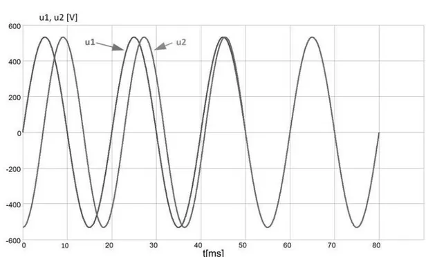
Figure 2 shows mee ng the synchroniza on require‐ ments for one phase of two electrical systems. Once the aforemen oned requirements are met, two power systems are connected.
In the vessel power systems the synchroniza on auto‐ ma on system has to keep up with the changes in the ves‐ sel network. As men oned before, vessel network is a ‘so ’ network that is characterized by frequent voltage and fre‐ quency changes (connec ng and disconnec ng of receivers of high power comparable to the power of a power gener‐ a ng system). Synchroniza on among autonomous auxilia‐ ry engines in vessel systems is performed automa cally and is realized by synchronisers. More or less technologically advanced synchronizers used in shipbuilding guarantee automa c synchroniza on in minimal me. Synchronizer T4500 by SELCO (a company well‐known in shipbuilding) can serve as an example of such synchroniser [6].
To meet the synchroniza on requirements, the synchro‐ nizer sends command signals to power‐genera ng speed governors and op onally, and not frequently, to genera‐ tors’ voltage regulators which are set to work in parallel. Mee ng the requirement of the phase order while turning on two power‐genera ng systems to perform parallel work is realized in generators’ assembly, and is not checked dur‐ ing synchroniza on. Voltage requirement is realized by gen‐ erators’ voltage regulators and the synchronizer usually does not influence the effec ve (root‐mean‐square) voltag‐ es’ adjustment. The main task of the synchronizer is to meet the frequency requirement and, what is even more important, the phase requirement. Mee ng both is done mechanically via the slight change in the generator’s driving motor revolu ons. High rota onal mass iner a of the driv‐ ing motor as well as its rota onal speed control system iner a extend me of the synchroniza on process up to a few minutes.
(1)
(2)
(3)
(4)
control
G
LAND
SIDE
SHIP SIDE
MSB
U control
converter
control converter
AC/AC DC/AC AC/DC
from grid net
network connector
Fig. 3 STS system synchroniza on
Using the aforemen oned synchronizers in STS system results in significant drawbacks:
Assuming that the synchronizer adjusts ship’s ne‐ twork parameters to the na onal grid parameters, motors’ revolu on adjustment of auxiliary engines will cause the frequency changes of the power re‐ ceivers currently supplied. This is not beneficial for the receivers whose rotary mechanisms are associa‐ ted with the frequency of supplying voltage. Asyn‐ chronous squirrel‐cage motors are the main receiver in the vessel systems. Rota onal speed is propor onal to supplying frequency:
where:
f ‐ supplying voltage frequency p ‐ number of synchronous field pole
Low dynamics of the synchroniza on system – long synchroniza on process (especially at high powers of auxiliary engines)
In order to eliminate the drawbacks of the synchroniza‐ on system realized with the use of classic synchronizers the most appropriate way of synchroniza on is to control the frequency inverter accordingly (Fig. 3).
As men oned before, the phase requirement is the ma‐ in requirement for the synchroniza on to be performed. There are many methods that allow for determining ne‐ twork’s phase and its voltage frequency. As an example can
serve a network’s phase determining method that is detec‐ on of moment at which voltage goes through zero point. During the voltage course there are only two such mo‐ ments at which the voltage goes through zero point. The risk of voltage distor on (caused by connec ng high power receivers in case of ‘so ’ network, for instance) that intro‐ duces errors to the controlling system cannot be disregar‐ ded. This method is characterized by low dynamics and precision [7].
Over the recent years, there has been a great deve‐ lopment of semiconductor technology and controlling ba‐ sed on CPU and digital techniques. Thanks to this deve‐ lopment a PPL (Phase‐Locked‐Loops) synchroniza on sys‐ tem, well‐known in electronics, found applica on in electri‐ cal power systems. PPL system is used in electronic systems of frequency division and mul plica on, frequency synthe‐ sis, demodula on and synchroniza on. Phase synchroniza‐ on system based on PLL consists of three main func onal blocks (Fig. 4):
PF – phase detector compares different phase angles of the input signal X(t) and output signal Y(t) from voltage‐controlled oscillator VCO and produces volta‐ ge error signal ΔX(t) that depends on the difference in phases and frequency.
LF – lowpass filter, in which the filtra on of the error signal high frequency takes place, and then the filte‐ red signal ΔXF(t) is sent to the voltage‐controlled oscillator VCO.
Error signal ΔXF(t) voltage‐controlled oscillator VCO.
Fig. 4 Basic conceptual models of PLL
6 ∗
Fig. 5 Block diagram of the PLL to synchronize na onal grid’s converter with the ship’s network VaVbVcMSB‐ three‐phase voltage vectors on Main Switch Board – MNS
VaVbVcCON‐ three‐phase voltage vectors of AC/AC converter
Abovemen oned conceptual model of PLL can be used in the process of synchroniza on between na onal grid and ship’s electrical network. Figure 5 presents a block diagram of the PLL where PLL synchronizes na onal grid’s converter with the ship’s network. PLL’s task is to keep the phase compa bility of the vessel network voltage (VaVbVcMSB – three‐phase voltage vectors on Main Switch Board – MNS) with the output voltage of STS system converter ( – three‐ phase voltage vectors of AC/AC converter).
There are some limits to the system analysis of the in‐ stantaneous values of voltages [8]. Thus, for the purpose of descrip on, analysis and control of the converter the no‐
on ‘space vector’ is used. Three‐phase instantaneous valu‐ es of voltages are transformed to the two‐phase equiva‐ lent rota ng Cartesian coordinate system (Park’s transfor‐ ma on) [9] (6) on the basis of symmetrical component vec‐ tors’ theory.
SYNCHRONIZATION SYSTEM ANALYSIS
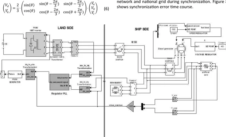
A simula on analysis of the synchroniza on system of na onal grid with autonomous ship’s network employing PLL system was performed with the use of MATLAB‐ SIMULINK package. The system presented in the Figure 6 has been modelled.
For the correct control of the converter in order to convert abc coordinate system to dq coordinate system and the other way round (Park’s transforma on) sine‐ cosine generator has to be used. Sine‐cosine signal has to be precisely synchronised with the ‘so ’ vessel network. To achieve this the phase voltages of the phase (Ua MSB) and line‐to‐line voltage between the phases (Uab MSB) have been used. The voltages men oned are orthogonal.
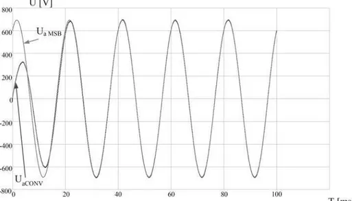
Figure 7 and 8 present the results of the simula on ana‐ lysis of the STS synchroniza on system employing PLL. Figu‐ re 7 presents phase voltages’ me courses of both ship’s network and na onal grid during synchroniza on. Figure 8 shows synchroniza on error me course.
sin
cos
sin cos
sin
cos (6)
Fig. 6 The simula on model of synchroniza on in the STS system employing PLL
Fig. 7 Voltage Waveform of Phase "a" Ua MSB of ship network and Voltage Waveform of Phase "a" of converter STS system Ua CONV
during synchroniza on with using PLL
Fig. 8 Synchroniza on error me course employing PLL
CONCLUSIONS
Providing uninterrup ble work of vessel electrical devi‐ ces is directly connected to safety of the ship. When a ship lies in port, its connec on to the power supply from na o‐ nal grid has to be performed with the use of synchroniza‐ on between na onal grid and ship’s network. The idea of synchroniza on system employing PLL presented in the ar cle shows the following merits:
high dynamics of the synchronisa on system – the connec on between the systems can be realized a er only two periods (40ms),
‘adjustability’ of na onal grid (that is not loaded be‐ fore the connec on) to ‘so ’ vessel network.
REFERENCES
[1] Tarnapowicz D., Borkowski T., Nicewicz G.: Ships moor‐ ed in the port with threat to the natural environment. Management Systems in Produc on Engineering. No 2 (6), 2012.
[2] Tarnapowicz D.: An alterna ve power supply: the use of ships in port as an environmentally friendly solu on. Management Systems in Produc on Engineering. No 3 (3), 2011.
[3] EU (2006/339/EC) COMMISSION RECOMMENDATION of 8 May 2006 On the promo on of shore‐side electri‐ city for use by ships at berth in Community ports (Text with EEA relevance).
[4] Białek R, Gnat K.: Elektrotechnika dla studentów Wy‐ działu Nawigacyjnego. WSM. Szczecin 2000.
[5] Grono A, Redlarski G, Zawalich J.: Komputerowe wspo‐ maganie badania układów automatycznej synchroniza‐ cji prądnic. Wydawnictwo Politechniki Gdańskiej. Gdańsk 2005.
[6] SELCO: Protec on relays and controls catalog may. 2012.
[7] Piróg S i in.: Metody synchronizacji przekształtników energoelektronicznych z siecią zasilającą. Przeglad Elek‐ trotechniczny. Nr 2,2010.
[8] Fernández F.D.F.: Contribu ons to Grid‐ Synchroniza on Techniques for Power Electronic Converters. Vigo University Department of Electronic Technology. 2009.
[9] Park R.: Two reac on theory of synchronous machines. AIEE Transac ons. Vol. 48, 1929, pp. 716‐730.
dr inż. Dariusz Tarnapowicz
Mari me University of Szczecin, Faculty of Mechanical Engineering Department of Marine Electrical Engineering and Electronics ul. Wały Chrobrego 1‐2, 70‐500 Szczecin, POLAND
e‐mail: [email protected]
![Figure 1 presents vessel electrical power supply system con fi gura on (STS) in the port according to EU regula ons [3]](https://thumb-eu.123doks.com/thumbv2/123dok_br/18119195.323997/1.910.241.685.910.1168/figure-presents-vessel-electrical-power-supply-according-regula.webp)