Vol. 7, No. 2, November 2010, 217-229
FLC Based Adjustable Speed Drives
for Power Quality Enhancement
Darly Sukumar
1, Vanaja Ranjan
1, Benjamin Justus Rabi
2Abstract: This study describes a new approach based on fuzzy algorithm to suppress the current harmonic contents in the output of an inverter. Inverter system using fuzzy controllers provide ride-through capability during voltage sags, reduces harmonics, improves power factor and high reliability, less electromagnetic interference noise, low common mode noise and extends output voltage range. A feasible test is implemented by building a model of three-phase impedance source inverter, which is designed and controlled on the basis of proposed considerations. It is verified from the practical point of view that these new approaches are more effective and acceptable to minimize the harmonic distortion and improves the quality of power. Due to the complex algorithm, their realization often calls for a compromise between cost and performance. The proposed optimizing strategies may be applied in variable-frequency dc–ac inverters, UPSs, and ac drives
Keywords: Harmonic distortion, Impedance source inverter, Pulse width modulation.
1 Introduction
In recent years, a variety of power electronics equipment with PWM inverters which are widely used in industrial applications and power network systems have caused significant inherent problems, such as generation of reactive current and power, as well as higher harmonic distortion in the utility power sources. The traditional inverters are voltage source inverter and current source inverter. Which consists of a diode rectifier front end, dc link and inverter bridge. In order to improve power factor, either an ac inductor or dc inductor is normally used. The dc link voltage is roughly equal to 1.35 times the line voltage, and the V-source inverter is a buck converter that can only produce an ac voltage limited by the dc link voltage. Because of this nature, the V-source inverter based PWM VSI and CSI are characterized by relatively low efficiency because of switching losses and considerable EMI generation. Since switches are used in the main circuit, each is traditionally composed of power transistors and anti parallel diode. It provides bi-directional current flow and
1Department of Electrical and Electronics Engineering, Anna University, Chennai, India;
E-mail: jnfdarly@yahoo.co.in
2Department of Electrical and Electronics Engineering, RREC, Chennai, India;
E-mail: bennisrobi@rediffmail.com
unidirectional voltage blocking capability. Thus inverter presents negligible switching losses and EMI generation at the line frequency. The tackles, which exist in the voltage inverter, are an output LC filter needed to provide sinusoidal voltage compared with current source inverter. The LC filter causes additional power loss and controlled complexity. To avoid short-circuiting of damaging dead line is allowing which provides a delay time between gating signals but it causes waveform distortion.
ASD system suffers the following common limitations and problems. Obtainable output voltage is limited quite below the input line voltage. The diode rectifier fed by the 415 volts ac line produces about 560 volts dc on the dc-link, which is roughly 1.35 times the line-to-line input voltage under the assumption of heavy load and continuous “double–hump” input current for large drives that typically have an approximately 3% of inductance on the ac or dc side.
For light load operation or small drives with no significant inductance, the line current becomes discontinuous “double-pulse”, and the dc voltage is closer to 1.41 times the line-to-line input voltage 400 V motor, the low obtainable output voltage significantly limits output power that is proportional to the square of the voltage. This is a very undesirable situation for many applications because the motor and drive system has to be oversized for a required power. Voltage sags can interrupt an ASD system and shut down critical loads and processes. Over 90% of power quality related problems are from momentary voltage sags of 10-50% below nominal. The dc capacitor in drives is a relatively small energy storage element, which cannot hold dc voltage above the operable level under such voltage sags. The drives industry provides options using converter or boost converter with energy storage or diode rectifier to achieve ride-through, however, these options come with penalties of cost, size/weight, and complexity. Inrush and harmonic current from the diode rectifier can pollute the line. Low power factor is another issue of the traditional drives.
Performance and reliability are compromised by the V-source inverter structure, because miss-gating from EMI can cause shoot-through that leads to destruction of the inverter, the dead time that is needed to avoid shoot-through creates distortion and unstable operation at low speeds, and common-mode voltage causes shaft current and premature failures of the motor. A recently developed new inverter, the impedance source inverter, has a place for drives systems to overcome the aforementioned problems. A Z-source inverter based drives can:
•Produce any desired output a voltage, even greater than the line voltage, regardless of the input voltage, thus reducing motor ratings;
•Provide ride-through during voltage sags without any additional circuits;
In Sinusoidal Pulse Modulation scheme the pulse width is made sinusoidal function of the angular position of the pulse in the cycle. This type of modulation is realized by comparing sinusoidal wave and triangular wave. The frequency of the triangular wave decides the number of the pulses in each half cycle. Output amplitude control is achieved by controlling the amplitude of the sinusoidal signal. This scheme results in the finite lower order harmonic contents [1]. In Random Modulation of PWM scheme the concentrated energy at switching frequency can be smeared over a wider bandwidth by randomizing the switching angle about the nominal switching angles [2]. In sinusoidal PWM, this can be selected by modulating carrier with a band limited random signal [3, 4]. This technique is found useful for acoustic noise reduction in PWM inverter fed drives [5]. To achieve the random modulation, 12 noise sequences of zero mean and uniform amplitude distribution are generated and one each is added the 12 switching angles [6]. In Staircase PWM modulation scheme several pulses per half cycle are used. This modulation is realized by comparing staircase wave and triangular wave. Here the output amplitude control is done by controlling levels of staircase wave [7]. In this scheme also there are finite lower order harmonic contents.
Programmed PWM is basically the MMSR scheme in which different output fundamental amplitudes, the switching angles are computed off-line and stored readily for use. This scheme requires many wave-forms to be stored in memory for previous values of output fundamental magnitude [8]. Multiple Pulse Modulation with Selective Elimination of Harmonics is based on the principle of selecting suitable M pulse positions per quarter cycle to eliminate any M harmonics and obtaining output voltage variation by controlling the pulse width symmetrically around the pulse position. But this involves complex computations for obtaining the pulse position for various output amplitudes. A unified approach for generating pulse width modulation patterns for three- phase voltage source inverter that provides unconstrained selective harmonic elimination and fundamental current control [9]. The requirement of Z-source network has been discussed in [10], which should not differ much from the traditional drives.
issues in random PWM method, first, output harmonic distortion have not been alternately improved and second, the output harmonic intensity of the inverter may always randomly change with various random sources. Hence the random modulation may not ensure the optimum power quality of the inverter output at all times.
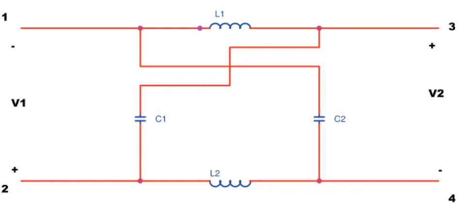
Impedance network: The lattice networks are used in filter sections and are also used as attenuators. Lattice networks are sometimes used in preference to ladder structure in some special applications. This lattice network, L1 and L2
are series arms inductances; C1 and C2 are diagonal capacitances. This is a
two-port network that consists of split inductors L1 and L2 and capacitors C1 and C2
connected in X-shape. This network is coupled with the main circuits and the source to describe the operating principle of inverter in Fig. 1.
L1 L2 C1 C2 V1 V2 + + -1 2 3 4
Fig. 1 – Equivalent circuit of the impedance network.
The three-phase impedance source inverter bridge has nine permissible switching states unlike the traditional voltage source inverter that has eight switching states. The impedance source inverter bridge has one extra zero state. When the load terminals are shorted through both upper and lower devices of any one-phase leg or all three-phase legs. This shoot through zero state is forbidden in the VSI, because it would cause a shoot-through. This network makes the shoot through zero state possible. This state provides the unique buck-boost feature to the inverter.
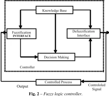
Fuzzy logic controller: The basic configuration of a fuzzy logic controller comprises of four principle components.
•Fuzzification interface;
•Knowledge base;
•Decision making logic;
The first stage in all FLCs is the fuzzification of inputs. the proposed FLC takes error and change in error of the output state as inputs. Considering an FLC with triangular input and output membership functions and can be expressed as a fuzzy associative memory .The heart of an FLC is the rule/knowledge base represented by FAM. Digital implementations is done through digital to analog conversion process.
Fig. 2 – Fuzzy logic controller.
Fuzzy rules and inferences: For fuzzy logic control, a few more concepts such as fuzzy implication and fuzzy composition are important. A fuzzy rule typically has an IF–THEN format,
IF x is A and y is B then z is C
Where x, y and z are fuzzy variables and A, B and C are fuzzy subsets in the universe of discourse X, Y, and Z respectively. If the conditions expressed in the ‘IF’ portion are met, then the action specified in the ‘THEN’ portion are taken. In order to design a fuzzy controller a fuzzy rule base consisting of several rules must be constructed.
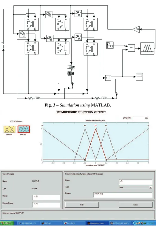
Fig. 3 – Simulation using MATLAB.
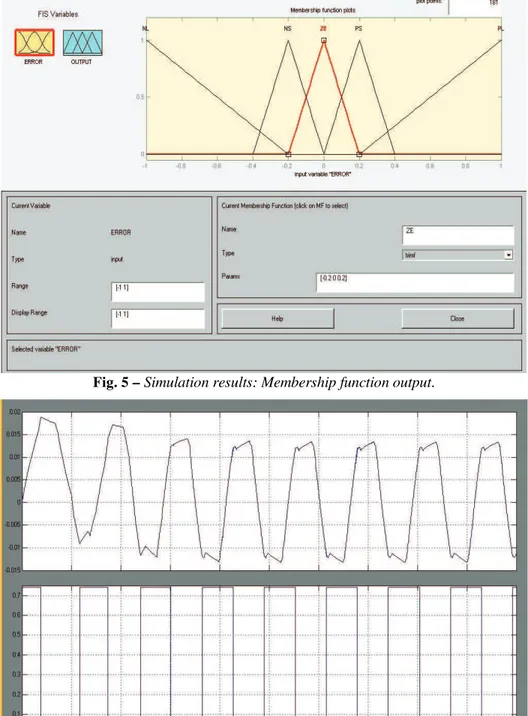
Fig. 5 – Simulation results: Membership function output.
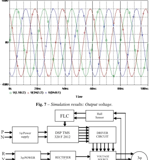
Fig. 7 – Simulation results: Output voltage.
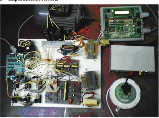
Fig. 8 – Block Diagram of Experimental Set-up.
2 Experimental
Results
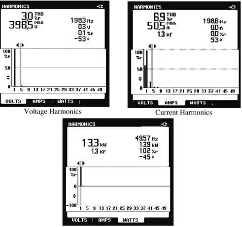
Fig. 9 – Photo of experimental setup.
The inverter modulation index was 1.0, producing the same DPWM waveform as the traditional inverter. However, the magnitude of the output voltage was boosted to 415 V rms and was confirmed by the sinusoidal waveform after the LC filter. The traditional PWM inverter cannot produce 400V rms output voltage. The boost factor B was is noted that the line current contains negligible harmonics than the traditional ASD system without dc inductors and appreciably less harmonics that the traditional ASD system even with dc inductor because of both the Z-source inductors and input capacitors. Again, the line current harmonics have been reduced greatly
A prototype has been built to further verify the operation; the critical relationships of voltage boost, and simulation results of the presented FLC based Z-source ASD system. It should be noted that the inductors and capacitors were oversized in the prototype for possible regenerative operation during deceleration or inverter trips. For large drives a dc inductor is commonly used to minimize line harmonic current and voltage distortion.
performance of the proposed Fuzzy logic controller based Harmonic elimination of an inverter has been demonstrated experimentally. The performance of the proposed Fuzzy logic controller based Harmonic elimination of an inverter has been demonstrated experimentally and shown in Fig. 10. Using Harmonic Analyzer the following results were obtained. Digital Signal Processor TMS320 F2812 board is available from Texas instruments as a development tool. It is one of the processors that execute most of the programs of the control algorithm. The DSP kit provides a complete development environment, and includes the DSP board, power supply, on-board JTAG compliant emulator and specific version of the Code Composer Studio Integrated development Environment. The DSP board itself has nearly all peripheral signals available on the board headers, making it easy to interface the board with other system hardware. Orbitron type – IRFP450 MOSFET is selected for this research which has the ratings as 10 A, 500 V.
Voltage Harmonics Current Harmonics
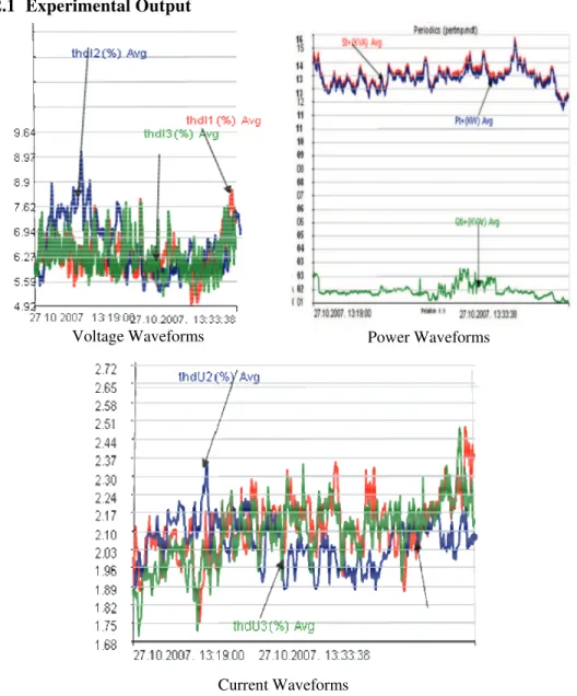
2.1 Experimental Output
Voltage Waveforms Power Waveforms
Current Waveforms
Fig. 11 – Experimental Waveforms under the nominal voltage of 415V.
3 Conclusion
modulation process. The FLC based inverters are applicable for induction motors, arc furnaces and polluting loads. Simulation and experimental studies have demonstrated that the new techniques are promising methods and economical approaches to improve the power quality of PWM inverters. Simulation and experimental results verified the operational and demonstrated the promising features. In summary, the Z-source inverter ASD system using intelligent controllers has several unique advantages that are very desirable for many ASD applications, it:
•Can produce any desired output voltage, even greater than the line voltage;
•Provides ride–through during voltage sags without any additional circuits and energy storage;
•Minimizes the motor ratings to deliver a required power;
•Reduces harmonic current.
•Unique drives features include buck-boost inversion by single power-conversion stage,
•Improved reliability, strong EMI immunity, and low EMI
•The Impedance source technology can be applied to the entire spectrum of power conversion.
•
Obtained output waveform with negligible distortion factor.4 References
[1] T.G. Habetler, D.M. Divan: Acoustic Noise Reduction in Sinusoidal PWM Drives using a Randomly Modulated Carrier, IEEE Transaction on Power Electronics, Vol. 6, No.3, July 1991, pp. 356 – 363.
[2] A.M. Trzynadlowski, F. Blaabjerg, J.K. Pedersen, R.L. Kirlin, S. Legowski: Random Pulse width Modulation Techniques for Converter-fed Drive Systems - A Review, IEEE Transaction on Industry Application, Vol. 30, No. 5, Sept/Oct. 1994, pp. 1166 – 1175. [3] J.K. Pedersen, F. Blaabjerg: Digital Quasi-random Modulated SFAVM PWM in an AC-drive
System, IEEE Transaction on Industry Electronics, Vol. 41, No. 5, Oct. 1994, pp. 518 – 525. [4] S. Legowski, A.M. Trzynadlowski: Hypersonic MOSFET-based Power Inverter with
Random Pulse Width Modulation, IEEE Industry Applications Society Annual Meeting IEEE-IAS 1989, Vol. 1, San Diego, CA, USA, Oct. 1989, pp: 901 – 903.
[5] J.T. Boys, P.G. Handley: Spread Spectrum Carrier: Low Noise Modulation Technique for PWM Inverter Drives, IEE Proceedings-B, Vol. 139, No. 3, May 1992, pp. 252 – 260. [6] Y. Konishi, M. Nakaoka: Current-fed Three Phase and Voltage-fed Three Phase Active
Converters with Optimum PWM Pattern Scheme and their Performance Evaluations, IEEE Transaction on Industrial Electronics, Vol. 46, No. 2, Apr. 1999, pp. 279 – 287.
[8] M. Liserre, A.D. Aquila, F. Blaabjerg: Genetic Algorithm-based Design of the Active Damping for an LCL-filter Three-phase Active Rectifier, IEEE Transaction on Power Electronics, Vol. 19, No. 1, Jan. 2004, pp. 76 – 86.
[9] J.R. Espinoza, G. Joos, J.I. Guzman, L.A. Moran, R.P. Burgos: Selective Harmonic Elimination and Current/Voltage Control in Current/Voltage-source Topologies: A Unified Approach, IEEE Transaction on Industrial Electronics, Vol. 48, No. 1, Feb. 2001, pp. 71 – 81. [10] H.G. Sarmiento, E. Estrada: A Voltage Sag Study in an Industry with Adjustable Speed
Drives, IEEE Industry Application Magazine, Vol. 2, No. 1, Jan/Feb. 1996, pp. 16 – 19. [11] A.V. Zyl, R. Spee, A. Faveluke, S. Bhowmik: Voltage Sag Ride-through for
Adjustable-speed Drives with Active Rectifiers, IEEE Transaction on Industry Application, Vol. 34, No. 6, Nov/Dec. 1998, pp. 1270 – 1277.
[12] A.V. Jouanne, P.N. Enjeti, B. Banerjee: Assessment of Ride-through Alternatives for Adjustable-speed Drives, IEEE Transaction on Industry Application, Vol. 35, No. 4, Jul/Aug. 1999, pp. 908 – 916.
[13] Y.S. Kim, S.K. Sul: A Novel Ride-through System for Adjustable-speed Drives using Common-mode Voltage, IEEE Transaction on Industry Application, Vol. 37, No. 5, Sep/Oct., 2001, pp. 1373 – 1382.
[14] J.L.D. Gomez, P.N. Enjeti A.V. Jouanne: An Approach to Achieve Ride-through of an Adjustable-speed Drive with Flyback Converter Modules Power by Super Capacitors, IEEE Transaction on Industry Application, Vol. 38, No. 2, Mar/Apr. 2002, pp. 514 – 522.