ISSN: 1553-345X
©2014 Science Publication
doi:10.3844/ajessp.2014.35.43 Published Online 10 (1) 2014 (http://www.thescipub.com/ajes.toc)
Corresponding Author: Lovelin Jerald, A., Faculty of Engineering, Avinashilingam University for Women, Coimbatore, Tamilnadu, India
INVESTIGATIONS ON THE PERFORMANCE OF VAPOUR
COMPRESSION SYSTEM RETROFITTED WITH ZEOTROPIC
REFRIGERANT R404A
1
Lovelin Jerald, A. and
2D. SenthilKumaran
1
Faculty of Engineering, Avinashilingam University for Women, Coimbatore, Tamilnadu, India
2
Adithya Institute of Technology, Coimbatore, Tamilnadu, India
Received 2013-10-28; Revised 2014-01-03; Accepted 2014-02-11
ABSTRACT
The environmental impacts like global warming and ozone depletion has become a challenge to the refrigeration and air conditioning industry. Chloro Fluoro Carbons (CFCs) and Hydro Flouro Carbons (HCFCs) are referred to as an Ozone Depleting Substances (ODS) because once these gases are released into the environment and reach the stratosphere, depletes the ozone layer. This research paper aims to study the performance characteristics of an R12 (CFC) vapour compression refrigeration system retrofitted with zeotrope blend of refrigerant R404a, used for cooling liquids with five different configuration of capillaries of diameters 0.033”, 0.036”, 0.044”, 0.050” and 0.30” (2 Way). The refrigerant R404a is an alternate refrigerant to CFCs and HCFCs as they are ozone friendly and have less Global Warming Potential (GWP) than R12 and R134a. The parameters employed in analysis of the performance characteristics are the Evaporator load (Qe), Coefficient of Performance (COP), Work done by the compressor (Wc) and Refrigeration Effect (RE). A detailed experimentation was carried out to compare the performance and effectiveness of the system using five different capillaries. The result obtained from the observation will help to identify the optimum diameter of capillary which could be used in the system to give the best performance.
Keywords: Ozone Depletion, Global Warming, Zeotrope Blends, Vapour Compression System Optimum Diameter, Capillaries
1. INTRODUCTION
Refrigeration finds its major application in domestic, commercial, industrial, transport and Food preservation and pharmaceutical industries. Due to the phase out of CFC which was responsible for major ozone depletion and global warming are now being replaced by substitutes which are friendly to the environment. of R404a is Zeotropic refrigerant blend of R125/143a/134a (44, 52, 4%) which can be a suitable alternate for R134 a, R410a and CFC R502 Zeotropic refrigerants therefore do not boil at constant temperatures unlike azeotropic refrigerants. Any substitute should generally possess some ideal properties like non flammability, non toxic, friendly to the natural environment, stable at all
operating conditions and have similar characteristics of the refrigerant for which Hydro Flouro Carbons (HFC’s) and its blends of refrigerants such as zeotropes are finding its applications in most of the commercial refrigeration sector as alternatesubstitutes and are cost effective Li and Zhao (2008).
parameters of the system revealed that R507 can be used successfully as a retrofitting refrigerant in existing window air-conditioners originally designed to use R22 in the event of HCFC phased out. Peethambaran and Kumar (2008) developed a simulation model to determine the suitability of an eco-friendly refrigerant for vapour compression refrigeration systems, which helps to predict the behaviour for all possible combinations against the actual experimental study within the tolerance limit set. Pyasi and Gupta (2011) presented analytical results of analyzing blends of HFC refrigerants such as 404a and 508b in Cascade Refrigeration System.
Experimental and theoretical studies on capillary tube began in the 1940s and a lot of models and algorithms have been developed to meet different requirements. Dalkilic et al. (2003) studied the performance analysis of alternative new refrigerant mixtures like 134A, 404A, 407C, HFC-410A and HFC-507 as substitute for R12, R134a and R 22. Akintunde (2011) obtained the validation of a design model for vapor compression refrigeration system. This model was used to design a vapor compression refrigeration system. The analysis included three basic parameters as evaporator Temperature (Te), Condenser Temperature (Tc) and temperature difference in cascade condenser (Dt). Analysis results also give the optimum values of the evaporator, condenser and cascade condenser temperature. Jain et al. (2011) discussed on several refrigerants that have emerged as substitutes to replace R22, the most widely used fluorocarbon refrigerants in the world. These include the environmentally friendly Hydroflourocarbon’s (HFC) refrigerants such as R134a, R410A, R407C and M20.
Sagia and Paignigianns (2005) and Stegou-Sagia et al. (2006) developed a useful theoretical model of enthalpy and entropy properties of R404a and R410a have used Martin-Hou equation of state and the equation of ideal gas heat capacity at constant pressure, used relevant partial derivatives of pressure and derived mathematical expressions for exergy losses and COP for heat pump cycles Rajan (2011) has extensively studied and developed a computer model simulation to specifically compare the performance of R410a and R404a in a supermarket freezer display case system designed for R404a with a standard capacity of 3.42 kW. Grecoa and Vanoli (2005) presented a study to develop an accurate flow boiling heat transfer database for several important new fluids, provide data to the refrigeration industry for the design of high efficiency evaporators, compare the thermal performances of R134a, R507, R404A and
R410A to R22 (which they replace) and investigate the influence of the evaporating pressure and of the heat flux on the flow boiling characteristics of the fluids.
Qureshi and Zubair (2012) investigated on the performance characteristics due to use of different refrigerant combinations like R134a and R717 in basic vapor compression cycles with dedicated mechanical sub-cooling, R134a used in both cycles produced the best results in terms of COP, COP gain and relative compressor sizing.
Domanski et al. (2013) developed an evolutionary algorithm to explore the performance of hypothetical refrigerants defined by the thermodynamic parameters used by the extended corresponding states model for fluid properties. The results of his study states that R404a had increased COP in the evaporator COP and condenser than R410a Ferreira et al. (2003) examined the affects of magnetic field relating to the thermophysical properties of the four refrigerants, including R410a and R404a. The results of his study states that R404a had increased COP in the evaporator COP and condenser than R410a. Patil (2012) reported on the performance of an HFC-404A refrigeration system for a smooth U-tube con-denser and a micro-fin U-tube condenser for various operating conditions and observed that the cooling capacity of the system is increased by 10% and the coefficient of performance of the system is improved up to 17% using a micro-fin tube condenser. Chinnaraj et al. (2011) conducted experimental studies on smaller capacity R22 window air conditioner with Electronic Expansion Valve (EEV) is retrofitted with R407C and R290 and compared the performance given by R22, the Coefficient of Performance (COP) given by R407C and R290 is improved in the range of 4.8-7.1 and 8.0-12.3% respectively and the Energy Efficiency Ratio (EER) is increased by 4.2-6.9% for R407C and 6.4-10.8% for R290.
1.1. Working of a Refrigeration System
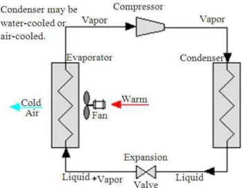
liquid refrigerant is forced through a metering or throttling device, also known as an expansion valve (essentially a pin-hole sized constriction in the tubing) to an area of much lower pressure. The sudden decrease in pressure results in explosive-like flash evaporation of a portion (typically about half) of the liquid. During evaporation, the liquid vapor refrigerant absorbs its latent heat of vaporization from the product which is to be cooled. This phenomenon known as “auto-refrigeration”. The typical lay out of the Vapour compression system in shown in Fig. 1. Refrigerant leaves the evaporator, now fully vaporized and slightly heated and returns to the compressor inlet to continue the cycle (Tiwari and Gupta, 2011).
The above Fig. 2 represents the pressure-enthalpy (p-h) diagram of a theoretical vapor compression refrigeration cycle. In this cycle, the refrigerant enters the compressor at state 1 at low pressure, low temperature and is compressed isentropically to dry
saturated vapor state. The compressed dry saturated refrigerant is discharged at state 2 as a high pressure, high temperature and super heated vapor. The superheated vapor enters the condenser where it gives out the latent heat to the surrounding condensing medium. The refrigerant enters the expansion devise where it experiences a sudden drop in the pressure and superheated vapor refrigerant is converted into partial wet vapor. The liquid vapor mixture of the refrigerant enters the evaporator at state 4 where it absorbs latent heat of vaporization from the medium which is to be cooled. The heat that is absorbed by the refrigerant at this stage is called the refrigeration effect. The refrigerant leaves the evaporator at low pressure, low temperature and saturated vapor at point 1 and the cycle is completed (Arora and Kaushik, 2008; Boloji, 2011). The various zero ozone depleting refrigerants used as substitutes in the refrigeration systems are listed in Table 1.
Fig. 1. Schematic diagram of a typical vapour compression system
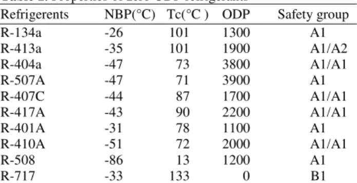
Table 1. Properties of zero ODP refrigerants
Refrigerents NBP(°C) Tc(°C ) ODP Safety group
R-134a -26 101 1300 A1
R-413a -35 101 1900 A1/A2
R-404a -47 73 3800 A1/A1
R-507A -47 71 3900 A1
R-407C -44 87 1700 A1/A1
R-417A -43 90 2200 A1/A1
R-401A -31 78 1100 A1
R-410A -51 72 2000 A1/A1
R-508 -86 13 1200 A1
R-717 -33 133 0 B1
2. MATERIALS AND METHODS
The experimental set up consist of a reciprocating compressor, an air cooled condenser, an expansion device usually a capillary device and coiled evaporator for cooling of liquids. Tests were carried out with R-12 vapour compression test rig retrofitted with R404a refrigerant for five different configurations of capillaries, 0.030”, 0.036”, 0.044”, 0.050” and two 0.33” (double), in the vapor compression refrigeration system. It is essential to note down the initial, final pressure and the corresponding temperature of each component to calculate the enthalpy at the various locations of the test rig. Pressure transducer are fitted at the inlet and outlet of the compressor to measure the inlet and outlet pressure and digital thermometers are used to measure the temperatures with the help of sensors which are attached to the components. Initially the system was allowed to stabilize and reach steady state for 30 min and then the readings were recorded from the system. A data sheet was created which included the readings obtained from the various units and calculations were performed. The plots obtained were compared to determine the most efficient and optimum diameter of capillary.
2.1. Instrumentation Used in The System
The measurements taken in the system are pressure, temperature at various locations in the apparatus and flow rate is measured using rotometer. These measurement points are as follows.
2.2. Temperature Measurements
• The inlet and outlet of the compressor • The inlet and outlet of the evaporator • Water temperature in the evaporator tank
2.3. Pressure Measurements
At inlet and outlet pressures of the test evaporator and compressor which are required to calculate theEnthalpy at various locations of the refrigeration system.
2.4. Methodology
The vapour compression system is initially cleaned by nitriding the entire system and the evacuation of the system is carried out with the help of a vacuum pump for nearly 30 min and then the refrigerant is charged with the help of the charging system. The system is charged with the zeotrope R404a refrigerant of nearly 800 gms and then the readings are recorded at equal interval of time.
2.5. Performance Assessment of Refrigeration
System
The cooling effect produced is quantified as Tons of Refrigeration (TR) Equation 1:
1 Tonn= ×Q Cp (Ti× −To) / 3024 (1)
where, Q is the mass flow rate of coolant in kg/min, Cp is the specific heat capacity of the product to be cooled in kJ/kg°C, Tiis the inlet, temperature of coolant to evaporator (chiller) in °C, Tois thre outlet temperature of coolant from evaporator (chiller) in °C.
Evaporator load for the system is given by Equation 2:
r
Qe=m (h1 h4)−
(2)
where, mr is the mass of the refrigerant, Kg/min, h1, is the enthalpy of compressor at inlet condition, Kj/kg, h4 is the enthalpy of the evaporator at outlet conditions KJ/kg.
Work of compression is given by Equation 3:
W=mr(h2−h1)
(3)
Effectively, the overall energy consumption would be towards the energy consumed by the compressor in KW.
Heat rejection in condensor is expressed by Equation 4:
Qc=mr(h2−h3)
(4)
COP carnot=Te / (Tc−Te) (5)
This expression also indicates that higher COP is achieved with higher evaporator temperature and lower condenser temperature. But COP is only a ratio of temperatures and hence does not take into account the type of compressor.
Hence the COP normally used in the industry is given by Equation 6 and 7:
Cooling effect (kw) COP
Power input to compressro (kw)
= (6)
e
COP=Q / W (7)
where, the Qe cooling effect is the difference in enthalpy across the evaporator and expressed as kW and W is the work of compression in kW. The capillary tube of 10 feet long of 5 different diameters of configurations coiled spirally is used in the experimental set up for carrying out the experiment. Data’s are recorded for every 10 min duration after allowing the vapour compression test rig to attain the steady state for nearly 30 min.
3. RESULTS
The experiment was conducted on a vapour compression system retrofitted with the zeotrope refrigerant R404a.Based on the recorded data the thermophysical properties with respect to effect of evaporator temperature,work of compression,evaporator load on refrigeration effect and mass flow rate,work of compression on actual COP were calculated and the results were graphically plotted as shown in Fig. (3-8).
The studies conducted previously by Tiwari and Gupta (2011) revealed that R404a refrigerant provided a better performance in terms of cooling efficiency, miscibility of oil and pull down time for different mass charges than R134a. The results of Akintunde (2011) reveal thal in helically coiled capillaries, the pitch between the coils does not have any influence on the performance of the system.
4. DISCUSSION
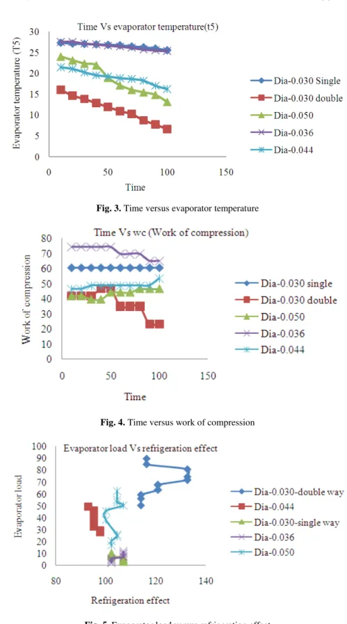
4.1. Effect of Evaporator Temperature
The cooling temperature is iversely proportional to time. Figure 3, indicates that when time increases the evaporator temperature decreases. As the
difference in evaporator temperature is high, the cooling efficiency of the system increases. For various diameters the graph were plotted from that the dia-0.030 (double way), has shown the lowest evaporator temperature, so that for refrigerant R404a dia-0.030 (double) is more efficient than other diameters.
4.2. Effect of Work of Compression
The work of compression is dependent on the suction pressure and temperature. It is evident from Fig. 4, that dia-0.030” (double) required less work of compression when compared to other diameters. This could be a justifying factor that refrigerant R404a is compatable and more efficient with the capillary of dia-0.030 “(double).
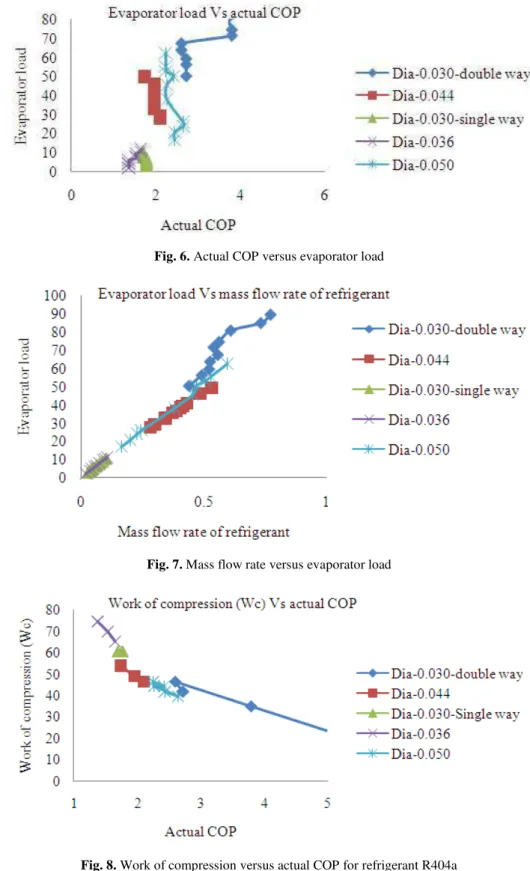
4.3. Effect
of
Evaporator
Load
on
Refrigeration Effect
The maximum refrigeration effect could be obtained by giving minimum evaporator load. Figure 5 clearly indicates that maximum refrigeration effect was attained for capillary with the dia of 0.030”(double) for refrigerant R404a with the evaporator load being minimum.
4.4. Effect of Evaporator Load on Actual Cop
The effect of evapourator load on Actual COP is represented in Fig. 6. The maximum COP was obtained with capillary of dia-0.030”(double) maximum evaporator load and dia-0.050” obtained moderate amount of performance at the moderate amount of evaporator load as compared with the others for refrigerant R404a.
4.5. Effect of Evaporator Load on Mass Flow
Rate of Refrigerant
The flow rate and the evaporator load are dependent on each other. It is evident from Fig. 7 as the flow rate of refrigerant increases the evaporator load also increases for the dia-0.030 double way and vise versa. The refrigeration effect obtained was also maximum for the above mentioned diameter for the refrigerant R404a.
4.6. Effect of Work of Compression on Actual Cop
Fig. 3. Time versus evaporator temperature
Fig. 4. Time versus work of compression
Fig. 6. Actual COP versus evaporator load
Fig. 7. Mass flow rate versus evaporator load
Hence the capillary of 0.030” (double) would be the optimum diameter for the experimental vapour compression system working with R404a.
5. CONCLUSION
The experimental study conducted with the zeotropic blend R404a, it was clear that the system provided better cooling capacity than R 134a. The pull down time was quite fast for R404a than R134 aand themiscibility of oil with R404a was better than R134a which resulted in the better efficiency in the system. The performance of the refrigeration system is mainly influenced by the operational parameters, such as ambient-condensing-evaporating-temperatures and mass flow rate. Also the amount of refrigerant charged was just 600 gms for zeotropic blends when compared to R134 at which required about 1kg to attain the same cooling capacity of the system. Moreover these refrigerants are environmental friendly and have the same thermo physical properties of R12 and R134a. Out of the five capillaries employed in the system, the cooling was coparatively quick with the capillary having the diameter 0.030” (double) when compared with the other capillaries like 0.030”, 0.044, 0.055”, 0.036”. The energy consumed is 20% less when compared to R134a. Hence it could be justified that zeotropic blends of refrigerant could be the best alternative for any refrigeration system.
The same experimental set up of vapour compression system could be operated with hydrocarbons like propane in future, which would significantly reduce the ozone depletion and global warming potential. Proper insulation and maintenance of adequate pressure in the refrigeration system would keep the risk of using hydrocarbons at bay and lead to sustainability in the refrigeration sector.
6. REFERENCES
Akintunde, M.A., 2011. Validation of a vapour compression refrigeration system design model. Am. J. Sci. Indus. Res., 2: 504-510. DOI: 10.5251/ajsir.2011.2.4.504.510
Arora, A. and S.C. Kaushik, 2008. Theoretical analysis of a vapour compression refrigeration system with R502, R404A and R507A. Int. J. Refrigerat., 31: 998-1005. DOI: 10.1016/j.ijrefrig.2007.12.015 Boloji, B.O., 2011. Performance investigation of
ozone-friendly R404A and R507 refrigerants as alternatives to R22 in a window air-conditioner. Energy Build., 43: 3139-3143. DOI: 10.1016/j.enbuild.2011.08.011
Calm, J.M., 2008. The next generation of refrigerants-Historical review, considerations and outlook. Int. J.
Refrigerat., 31: 1123-1133. DOI:
10.1016/j.ijrefrig.2008.01.013
Chinnaraj, C., R. Vijayan and P. Govindarajan, 2011. Analysis of eco friendly refrigerants usage in air-conditioner. Am. J. Environ. Sci., 7: 510-514. DOI: 10.3844/ajessp.2011.510.514
Dalkilic, A.S., N.A. Kurekci, O. Kincay and S. Wongwises, 2013. Fundamental basis and application of cold-room project design: A Turkish case study. Arab. J. Sci. Eng., 38: 1115-1130. DOI 10.1007/s13369-012-0534-5
Domanski, P.A., J.S. Brown, J. Heo, J. Wojtusiak and M.O. McLinden, 2013. A thermodynamic analysis of refrigerants: Performance limits of the vapor compression cycle. Int. J. Refrigerat. DOI: 10.1016/j.ijrefrig.2013.09.036
Ferreira, C.A.I., T.A. Newell, J.C. Chato and X. Nan, 2003. R404A condensing under forced flow conditions inside smooth, microfin and cross-hatched horizontal tubes. Int. J. Refrigerat., 26: 433-441. DOI: 10.1016/S0140-7007(02)00156-1
Grecoa, A. and G.P. Vanoli, 2005. Flow-boiling of R22, R134a, R507, R404A and R410A inside a smooth horizontal tube. Int. J. Refrigerat., 28: 872-880. DOI: 10.1016/j.ijrefrig.2005.01.008
Jain, V., S.S. Kachhwaha and R.S. Mishra, 2011. Comparative performance study of vapour compression refrigeration system with R22/R134a/R410A/R407C/M20. Int. J. Energy Environ., 2: 297-310.
Li, H. and Z. Zhao, 2008. Analysis of the operating characteristics of a low evaporation temperature R404A refrigeration system. Proceedings of the International Refrigeration and Air Conditioning Conference, (IRACC’ 08).
Patil, P.A., 2012. Performance analysis of HFC-404A vapor compression refrigeration system using shell and U-Tube smooth and micro-fin tube condensers. Exp. Heat Transfer: J. Thermal Energy Generat. Transport Storage Conver., 25: 77-91. DOI: 10.1080/08916152.2011.562343
Peethambaran, K.M. and N.A. Kumar, 2008. Eco-friendly vapor compression refrigeration system simulation analysis with double pipe evaporator and condenser. Int. J. Applied Eng. Res., 3: 1655-1669.
Qureshi, B.A. and S.M. Zubair, 2012. The effect of refrigerant combinations on performance of a vapor compression refrigeration system with dedicated mechanical sub-cooling. Int. J. Refrigerat., 35: 47-57. DOI: 10.1016/j.ijrefrig.2011.09.009
Rajan, S., 2011. Comparison of refrigerants R410a and R404a for use in low temperature applications: A computer model study. M.S. Thesis, University of Illinois at Urbana-Champaign.
Stegou-Sagia, A. and N. Paignigiannis, 2005. Evaluation of mixtures efficiency in refrigerating systems. Energy Conversion Manage., 46: 2787-2802. DOI: 10.1016/j.enconman.2005.01.007
Stegou-Sagia, A., A. Papadaki, V. Ioakim, 2006. R-410A and R-404A Real Gas Thermodynamic Relations and their Application for Predicting Exergy Efficiency in Vapor Compression Heat Pumps. Forsch. Ingenieurwesen, 70: 253-261. DOI: 10.1007/s10010-006-0038-0