High Temperature Flow Characteristics over a
Re-Entry Space Vehicle
Bruce Ralphin Rose. J
Assistant Professor, Department of Aeronautical Engineering, Regional Centre of Anna University, Tirunelveli, India, 627007
Saranya. P
PG scholar, Department of Aeronautical Engineering, Regional Centre of Anna University, Tirunelveli, India, 627007
Abstract- The viscous flow simulation over a re-entry vehicle in transonic and supersonic speed region using RANS (Reynolds-Averaged Navier-Strokes) equation is carried out from candidate configurations. The aerodynamic characterization of the launch vehicle configuration using turbulence model is done by Computational Fluid Dynamics. Few parametric studies related to the re-entry vehicles also carried out in the view of real time applications. The focus of this article is on viscous flows described by the RANS equations and the k-epsilon model for turbulence. The validity of the overall methodology is illustrated with several design examples, including the optimization of three-dimensional geometries in combination with advanced freeform techniques for mesh deformation. The solid modeling of re-entry vehicle is done using CATIA V5 design toolkit. Grid generation for the re-entry vehicle is performed by computational codes with required relaxation factor. The flow field simulation around the body has revealed several key facts that must be considered in the process of aerodynamic and structural design of re-entry vehicles.
Keywords – Re-entry vehicle, Hypersonic Flow, Optimization, CFD
I. INTRODUCTION
In the aerothermodynamics analysis, Computational Fluid Dynamics (CFD) is a preliminary part because of the advanced computer technology. It is an inexpensive alternative to the wind tunnel testing process, and CFD allows obtaining accurate solutions to a variety of aerothermodynamics concerns. Since, most of the aerodynamic theories fall apart in the transonic regime; it is hard to get accurate mock up of the re-entry vehicle in a wind tunnel to retrieve physical results [1]. Creating a mock up of the re-entry vehicle becomes a very time consuming and expensive task. However, when the design begins to advance the re-entry vehicle geometry begins to change. The constantly changing aero-thermodynamic loads are based on the geometric dimensions of the vehicle [2]. Whenever the geometry of the re-entry vehicle mock up needs to be built, and more number of wind tunnel tests are required.
The alternative to wind tunnel experiment is CFD analysis and it provides the similar type of information as a wind tunnel test in a timely, cost effective manner. Instead of paying for new re-entry vehicle mock ups to be created with various changes in geometry, it can be prepared with Computer Aided Design (CAD) tools. Then the CFD analysis will be carried out for each phases of the design, and costs associated with wind tunnel testing become obsolete. A CFD analysis on a launch vehicle can be broken down into few parts: (i). Creating a required model of re-entry vehicle in a computer program, (ii). Import the geometry into a meshing program, such as HYPERMESH, (iii). Analyze the meshed geometry in a CFD program by setting the design parameters and environmental conditions, (iv). Post-processing the output and evaluate the results [3].
The aero-thermodynamic loads are determined by means of CFD, at designated intervals throughout the launch. In order to exploit Fluent’s symmetry capability, a half model of the launch vehicle (1 kg) is developed. Splitting the re-entry vehicle in half reduces the complexity along with the amount of time to needed to solve the problem domain. To account for the fact that air flows around the launch vehicle, the area surrounding the re-entry vehicle model is meshed, rather than the re-entry vehicle itself [7]. A large rectangular prism is created that surrounding the re-entry vehicle to establish the flow field. The re-entry vehicle geometry has been subtracted from this rectangular prism by leaving the only area surrounding the vehicle to be meshed.
II. SOLID MODELING OF RE-ENTRY VEHICLE CONFIGURATION
The Re-entry vehicle design requires the selection of appropriate aerodynamic parameter forecasting methods. Factors of cost and schedule are considered along with the accuracy and reliability while selecting the prediction techniques. The objective of this concern is to minimize the uncertainties exist in aerodynamics, to attain the adequate solution for each specific requirement. Often the higher level optimization techniques will provide additional solution accuracy and increase the analysis costs.
Depending on the design phase, (conceptual, preliminary, and detailed design) the kind of results required are relied upon the selection of accuracy level and type of computational solver. The solvers should be enough to provide the acceptable margins and error bounds for the results. It has to be accomplished at each step of the analysis to maintain analysis costs control while providing the best possible results [8]. For example, general aerodynamic forces and moments are required over a wide range of Mach numbers for trajectory performance analysis as well as control system design. Detailed pressure distributions are required at a more limited set of flight conditions for structural design and analysis.
A. Design and Analysis Methods
The aerodynamic design and analysis of the Re-entry vehicle configurations require innovative use of analytical methods, CFD, and wind tunnel testing in an integrated design effort. Many prediction methods are available for re-entry vehicles application, ranging from engineering methods to CFD. The methods included at this point have been validated, and there is an experienced base to provide some confidence about the accuracy for specific flow conditions. It is also essential to understand the influence of configuration characteristics on the resulting aerodynamics. Hence, the appropriate selection of computational code is made for the flight conditions of interest. It is important that the results be available on a timely basis, and that the accuracy of individual results be assessed. The analytical results should be ‘good enough’ without being ‘too good’ because of the additional time and costs associated with using a higher level calculation methods.
The engineering methods proposed in the past are not adequate for this task, because of the critical nature of the centre of pressure on the orbital vehicle. It was recognized as Euler solutions have the minimum acceptable level of prediction that would provide the required accuracy for the range of Mach numbers of interest. Consequently, as the configuration changes during the preliminary design, the aerodynamic characteristics must be updated through iteration between Euler solutions and wind tunnel tests. As the solutions are converged, the Navier-Strokes equations will be used to provide detailed aerodynamic characteristics for those conditions [10]. As a part of the CFD effort, grids and solutions from independent sources are used to evaluate the quality of the predicted results.
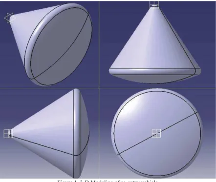
Figure 1. 3-D Modeling of re-entry vehicle
In order to exploit FLUENT symmetry capability, model of the re-entry vehicle is created a using CATIA V5 (Fig 1). It reduces the design complexity along with the amount of time required to solve the problem. The model is designated with an “.igs” extension file, and will be imported into GAMBIT where the meshing process is carried out. The fact is that the air flows around the re-entry or trajectory vehicle and not through it. Therefore, the area surrounding the re-entry vehicle is need to be meshed, rather than the re-entry vehicle itself. The re-entry vehicle geometry is then subtracted from this rectangular prism leaving only the area surrounding the re-entry vehicle to be meshed.
III. PROBLEM DESCRIPTION
A 3-D model of the re-entry capsule configuration is considered to establish the viscous flow simulations. Zero Angle of Attack (AoA) corresponds to a position, while the apex of the capsule cone points straight into the flow. At low supersonic conditions, the free-stream Mach number of 1.2, Static pressure of 220 Pa and Static temperature of 420o R are assumed.
Dimensions of the re-entry module highlighted in Fig (2) are as follows; Height of the module -3.269 mm, Base of the module -3.704 mm, Radius at the nose of the module – R 0.355, Base radius of the module –R 0.196. To determine the aero-thermodynamic loads at designated intervals throughout the launch, different AoA are assumed in the CFD simulations with associated boundary conditions.
The meshing process begins with the edges of the rectangular prism with a spacing ratio. The inner spacing of the module is set as 5 and the outer spacing of the module is set as 20 with triangular mesh for the trajectory vehicle. Using the edge mesh sizing as a guide, the faces of the re-entry vehicle and the faces of the rectangular prism are meshed. Next, the volume which is surrounding the vehicle will be meshed using a tetrahedral pattern.
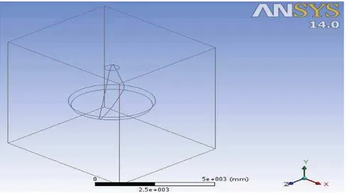
Figure 3. Imported file from CATIA V5 to ANSYS FLUENT
OVERFLOW is usually run as a Navier-Strokes viscous solver; however, it can also be run in Euler mode for inviscid solutions using a coarser grid. The Euler solutions discussed in the results part are from this code unless otherwise noted. The Navier-Stokes CFD solver has become efficient and flexible for large numbers of simulations over different re-entry vehicle configurations. The N-S flow solver for multi-block and structured grids utilizes capable mesh sequencing relaxation schemes to obtain steady state solutions. This provides the most comprehensive list of turbulence models, including 0-equation, 1-equation, and 2-equation models. CFL 3-D was used as a cross checking tool for other CFD solutions in the re-entry vehicle analysis.
Figure 4. Meshed model of re-entry vehicle (side view)
The mesh specifications illustrated in Fig (4) are as follows: Element type - Tetrahedral element, No. of elements – 18342, No. of nodes – 20243, Computational time required (As estimated) - 1 hour, Outer Spacing of the
20, Inner spacing -5, Dimensions of the control volume are as follows: Volume -10,000 mm3, X = 10,000 mm, Y = 10,000 mm, Z = 10,000 mm.
IV. RE-ENTRY VEHICLE MODULE ANALYSIS A. Results and Discussion
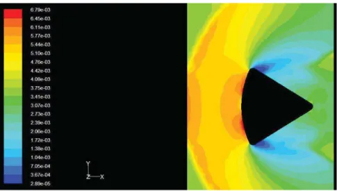
An implicit discretization of the pressure gradient terms in the momentum equations and continuity equation are used in the strong conservation form. While the re-entry vehicle enters into the atmosphere, a bow shock is created at the base of the vehicle [11]. The viscous flow simulation employed here is to study the physical and thermodynamic characteristics of this bow shock in a precise manner. At the two edges of the module base, the minimum magnitude of density is obtained. It shows the severe pressure drag at the two edges of the module base as displayed in Fig (5). Ideal gas assumption is used throughout the flow field analysis over the re-entry vehicle.
Figure 5. Density contour of the re-entry vehicle for Mach number 1.2
Both density based and pressure based coupled solvers are used for the flow field analysis. The density contour reveals the fact that the possibility of severe compressive stress at the base. The various AoA can relocate the locus of high density region along the vertical axis. High static pressure is created in the base of the re –entry vehicle as illustrated in Fig (6). Since, the pressure is high while re-entering in to the atmosphere due to the strong bow shock created .This bow shock will increase drag force acting on the re-entry vehicle and has the capability to decelerate the vehicle to low Mach numbers. The maximum static pressure is created at the far field of the re-entry vehicle because of the progressing bow shocks marching downstream of the vehicle [12]. The increase in pressure is visualized exactly using the static pressure contour for 0o AoA.
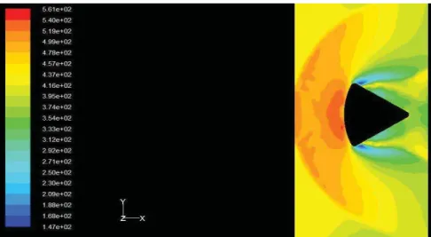
Air medium (atmosphere) is modeled as a single-species ideal gas. For the input Mach number 1.2 and operating conditions at the Tropopause boundary under consideration, real-gas thermodynamic non-equilibrium equation is used .Therefore an aero-thermo chemical model is not taken into account in the simulation process. The temperature variation obtained while entering into the atmosphere (during the re-entry) would be very high. For transonic Mach number boundaries, the temperature distribution around the vehicle is obtained as illustrated in Fig (7). The maximum temperature is produced at the base of the re-entry vehicle and it is lowest amount at the edges.
Figure 7. Static temperature created around the re-entry vehicle (k)
V. CONCLUSIONS
Applied CFD has been used extensively during the preliminary design of the module re-entry vehicle. Euler solution has proved to be useful as a practical design method and N-S solution is used for selected conditions. To obtain high accuracy and detailed flow field results N-S solution solver is needed. CFD methods can be used routinely for the prediction of aerodynamic characteristics of unusual and unconditional flight vehicles. It is an essential fact which is learned through the aerodynamic design and analysis using advanced simulation process. From this investigation, it is proved that this method can offer aerodynamic information on a timely basis while keeping the cost and schedule of commercial programs. More computational aerodynamic tools are required for the successful aerodynamic design and analysis of trajectory vehicles. Wind tunnel tests are important in the validation of prediction methods if they are not available, the aerodynamic analyst should consider the use of multiple independent codes to test the results for consistency.
VI. ACKNOWLEDGMENTS
We express our sincere thanks to Anna University, Tirunelveli Region for the computing resources and materials to complete this research work successfully.
REFERENCES
[1] Manish Kumar, Angela Lestari.,Konstantin A., “Numerical Simulation Of Massively Separated Flow Over A Model Of The Apollo Command Module”, Aerospace Sciences , AIAA, 10 Jan 2013.
[2] Yasuhiro Wada., “Numerical Simulation of Re-Entry Flow around the Space Shuttle with Finite-Rate Chemistry”, Journal of aircraft, Vol. 29, No. 6, Nov.-Dec. 1992.
[3] KojuHiraki.,Kenjiro.,Yasuoka,“Multi Degree-Of-Freedom Technique For Dynamic Characteristics Of Atmospheric Entry Capsule ,” 31st AIAA Applied Aerodynamics Conference - June 24-27, 2013.
[4] Bolt Beranek And Newman Inc. “A Review of Methods for Estimation Of aero acoustic Loads on Flight Vehicle Surfaces”. Cambridge, Massachfisetts, February 1977.
[5] Heinrich Lüdeke “Investigation Of Unsteady Loads Due To Turbulent Supersonic Wake Flow” DLR, Institute of Aerodynamics and Flow Technology, 2004.
[6] M.G.Walpot., Michaelj.Wright, Peternoeding, F Erryschrijer “Base Flow investigation Of The Apollo AS-202command module,” Progress in Aerospace sciences 57-74, 2012.
[7] N. Sreenivasa Babu, Dr. K. Jayathirtha Rao, “Analysis of Blunt Nose Cone with Ultra High Temperature Ceramic Composite Tps Materials”. International Journal of Innovative Research In Science, Engineering And Technology, Vol. 2, Issue 7, July 2013.
[9] .W. Kinzie, Brenda S. Henderson, and Harry H. Haskin “Aero acoustic Characteristics of Model Jet Test Facility Flow Conditioners”, Int. J. of Aero acoustics, AIAA, 2004.
[10] Dennis.G. Mabey, “Analysis and correlation of data on pressure fluctuations in Separated flow”, J. AIRCRAFT VOL. 9, Sep 1972. [11] Williaml. Kleb, And K. James weilmuenster, “Characteristics of the shuttle orbiter leeside flow during a Re-Entry condition”, Journal of
Spacecraft and Rockets Vol.31, No.1, January-February1994.
[12] Scott A. Stanfield “Hifire-1 Flight Data Analysis: Boundary Layer Transition Experiment during Reentry”. 50th AIAA, Aerospace Sciences, 09 - 12 January 2012.
[13] C.Y. Cheng, “Predictions of aero acoustic characteristics of coaxial jets”, AIAA JOURNAL Vol.15, No.3, March1977.
[14] Philippe Delorme, Pierre Mazet, Christophe Peyret, Yoan Ventribout, “Computational Aero Acoustics Applications Based On A Discontinuous Galerkin Method”, C. R. Mecanique, Science Direct, 9 September 2005.