Advances in Mechanical Engineering 2015, Vol. 7(9) 1–13
ÓThe Author(s) 2015 DOI: 10.1177/1687814015606308 aime.sagepub.com
Robust adaptive constrained
backstepping flight controller design
for re-entry reusable launch vehicle
under input constraint
Qin Zou
1, Fang Wang
2, Lianghua Zou
3and Qun Zong
4Abstract
A nonlinear constrained controller is designed for a reusable launch vehicle during re-entry phase in the presence of model uncertainty, external disturbance, and input constraint, via combining sliding mode control and adaptive backstep-ping control. Since the complex coupling between the translational and rotational dynamics of reusable launch vehicle, a control-oriented model derived from rotational dynamic is used for controller design. During the virtual control input design procedure, a dynamic robust term is utilized to compensate for the uncertainty. In addition, a filter is applied to handle ‘‘explosion of terms’’ problem during the actual control input design. To reduce the computational burden, adap-tive law is used to evaluate the unknown norm bound of the lumped uncertainty. An auxiliary system is constructed to compensate for the input constraint effect. The stability of the closed-loop system is analyzed based on Lyapunov theory. Simulation results demonstrate the validity of the developed controller in providing stable tracking of the guidance com-mand by numerical simulation on the 6-degree-of-freedom model of reusable launch vehicle.
Keywords
Reusable launch vehicle, adaptive control, backstepping control, sliding mode control, input constraint
Date received: 27 May 2015; accepted: 6 August 2015
Academic Editor: Hamid Reza Shaker
Introduction
Reusable launch vehicle (RLV) is designed to dramati-cally reduce the cost of accessing space by recovering and reusing after each mission. A major challenge posed in such mission is atmospheric re-entry. In this phase, a number of stringent constraints come into action that include constraints on heat flux, structural load, and so on, which restrict the vehicle to fly within a narrow flight corridor.1 Since advanced guidance and control technologies are critical for achieving safety, reliability, and cost requirements of RLV, these meth-ods have got more and more attention over the past few years. The major mission of re-entry guidance is the on-board correction of the flight path to make up for
model uncertainties and external disturbance. The impactful guidance law has been developed for calculat-ing the referenced angle of attack (AOA) and bank
1State Key Laboratory of Metastable Materials Science and Technology, School of Mechanics, Yanshan University, Qinhuangdao, China 2School of Science, Yanshan University, Qinhuangdao, China
3School of Europe and America, Hebei Normal University of Science & Technology, Qinhuangdao, China
4School of Electric and Automation Engineering, Tianjin University, Tianjin, China
Corresponding author:
Fang Wang, School of Science, Yanshan University, Qinhuangdao 066004, China.
Email: [email protected]
angle. Following, the focus is to design an attitude con-trol system to track the guidance command effectively, which is the key point of this article. Several approaches have been probed in the past, such as gain scheduling,2 dynamic inversion technique,3 trajectory linearization control,4 sliding mode control,5 and state-dependent Riccati equation strategy.6All these methods provided good performance. But input constraint was not taken into account.
Control input saturation is often encountered in practical applications due to the fact that it is usually impossible to implement unlimited control signals.7 Saturation is a potential problem for actuators of con-trol systems. It is frequently one of the main sources of instability, degradation of system performance, and parasitic equilibrium points of a control system.7 Physical input saturation on hardware dictates that the magnitude of the control signal is always constrained.8 Moreover, control input saturation often severely limits system performance, giving rise to undesirable inaccu-racy or leading instability.9In flight control system, the vehicle body may change seriously when input satura-tion occurs, and it may lead the vehicle to disintegrate. Thus, it is important to study the problem of flight con-trol system design subjects to input constraint. In addi-tion, the consideration of uncertainty and disturbance make the controller design more difficult.
Some methods are proposed to handle input con-straint for flight control system. Anti-windup control was designed to handle input constraint of hypersonic vehicles (HSVs) while the uncertainty was not consid-ered.10 Model predictive control has been employed extensively because of its inherent capability to imple-ment input constraint directly during the controller design procedure.11 However, it is dependent on the real-time receding horizon optimization and online opti-mization, and the determination of time-domain step size becomes the main barrier that restricts its applica-tion in HSV.12HNapproach was proposed for a linear-ized flexible airbreathing hypersonic vehicle (FAHV) model, uncertain parameters, and input constraints, where the linearized model was obtained by the feedback linearization approach.13But the high-order derivatives of outputs need to be computed. Using the differential geometry principle and the total energy theory, advanced flight control laws were designed for HSV in the pres-ence of actuator limitations.14Three adaptive fault con-trol schemes were proposed for airbreathing hypersonic vehicle (AHV) with external disturbances, actuator faults, and input saturation.15For the latter two control approaches, it did not need to know the upper bound of the external disturbances and the real minimum value of actuator efficiency factor in advance. An adaptive back-stepping attitude control scheme was developed for RLV in re-entry phase subjects to external disturbance and input constraint.16An adaptive dynamic surface control
strategy was designed for a HSV with actuator signals’ magnitude, rate, and bandwidth constraints.17 Then, to improve the tracking performance of designed controller and avoid a large initial control signal, an integral term was used at the level of dynamic surface control design.18 Moreover, a robust adaptive dynamic surface control strategy was investigated for a HSV with parametric model uncertainty and input saturation. When the input saturations occurred, a compensation design was used.19 A radial basis function neural network (RBFNN)-based adaptive dynamic surface control scheme was proposed for a HSV with the consideration of the magnitude, rate, and bandwidth constraints on actuator.20Furthermore, sliding mode control combining nonlinear disturbance observer and RBFNN was designed for a near space vehicle,21where RBFNN was constructed as a compen-sator to avoid the saturation nonlinearity of rudders. Two continuous time-varying sliding mode-based atti-tude controllers were designed to achieve the robust tracking of the attitude commands of RLV with and without a priori knowledge of upper bound on the lumped uncertainty.22 A finite-time robust flight con-troller, targeting for a re-entry vehicle with blended aerodynamic surfaces and a reaction control system,23 was presented for RLV. Based on multivariable smooth second-order sliding mode controller and disturbance observer, a re-entry attitude control strategy was pro-posed to guarantee that the guidance commands gener-ated from the guidance system can be tracked in finite time.24 Multi-time scale smooth second-order sliding mode controller with disturbance observer was pre-sented to ensure the finite-time re-entry attitude tracking despite the model parameter uncertainties and unknown external disturbances.25An adaptive multivariable distur-bance compensation scheme was proposed to provide the estimation for external disturbances where the bounds of the perturbations were not known. Based on the estima-tion, a continuous multivariable homogeneity second-order sliding mode controller was designed to ensure that the attitude tracking was achieved in finite time.26
RLV model
In this section, the rotational equations of motion of RLV during re-entry phase are described.
Attitude model
The motion of 6-DOF unpowered rigid flight vehicle is divided into translational motion and rotational (atti-tude) motion. Translational motion is referenced to a flight-path coordinate system, and it is caused by the forces that act on the vehicle. It is used for generating trajectory and designing guidance law. Most applica-tions assume steady, coordinated turns such that the sideslip angle is zero. The equations of translational motion are given by Groves et al.27
Since the primary task of the guidance and control system is to guide the RLV along a predetermined re-entry reference trajectory corridor. Because we focus on the control part of the guidance and control system, the translational equations of motion are not consid-ered herein. The re-entry attitude controller design is mainly based on the rotational equations of motion. The attitude equations of motion, which govern the rigid body attitude dynamic of the vehicle during the re-entry flight, are given as follows28,29
_
a= pcos (a) tan (b) +qrsin (a) tan (b) cos (s)
cos (b) g_
_
fcos (x)
(u_+OE) cos (f) sin (x)
+ sin (s)
cos (b) x_cos (g)
_
fsin (x) sin (g)
+ sin (s) cos (b)½f+ (
_
u+OE)( cos (f) cos (x) sin (g))
sin (f) cos (g) ð1Þ
_
b=psin (a)rcos (a) + sin (s)g_f_ cos (x)
+ (u_+OE) cos (f) sin (x)
+ cos (s)x_cos (g)f_sin (x) sin (g) cos (s)(u_+OE)( cos (f) cos (x) sin (g)
sin (f) cos (g)) ð2Þ
_
s= pcos (a) cos (b)qsin (b)rsin (a) cos (b) +a_sin (b)x_sin (g)f_ sin (x) cos (g)
+ (u_+OE) cos (½ f) cos (x) cos (g) + sin (f) sin (g)
ð3Þ
_
p= IzzMx IxxIzzIxz2
+ IxzMz IxxIzzIxz2
+ IxxIyy+Izz
Ixz
IxxIzzIxz2
pq
+ IyyIzz
IzzI
2
xz
IxxIzzIxz2
qr ð4Þ
_
q=My Iyy
+Ixz Iyy
(r2p2) + IzzIxx Iyy
pr ð5Þ
_
r= IxzMx IxxIzzIxz2
+ IxxMz IxxIzzIxz2
+ IxxIyy
Ixx+Ixz2
IxxIzzIxz2
pq
+ IyyIxxIzz
Ixz
IxxIzzIxz2
qr ð6Þ
wherea, b, and s, respectively, denote AOA, sideslip angle, and bank angle.p,q, andr, respectively, denote roll rate, pitch rate, and yaw rate. Mx, My, and Mz, respectively, denote rolling moment, pitching moment, and yawing moment.Iij(i=x,y,z;j=x,y,z) are iner-tia. h, v, u, f, g, and x, respectively, denote altitude, velocity, longitude, latitude, flight-path angle, and heading angle.OEis the Earth angular speed.
Robust adaptive constrained backstepping
controller design
In this section, the COM for the original model (1)–(6) is first developed. Attitude controller is developed under input constraint, model uncertainties, and exter-nal disturbance.
COM
Since the states of equations (1)–(6) are coupled with trajectory states, the COM is proposed to design con-troller succinctly.
Since rotational motion of RLV is much faster than translational motion and the motion of the Earth, the time derivatives of both position and direction of the velocity, and the Earth’s angular velocity are considered to be negligible with respect to the rotational motion. Thus, the Earth’s angular velocity and the translational terms in the rotational equations can be set to zero, that is,OE= 0, andg_=x_=f_ =u_=0.
Then, the rotational equations (1)–(3) resulting in the following equations
_
a=pcos (a) tan (b) +qrsin (a) tan (b)
_
b=psin (a)rcos (a)
_
s=pcos (a) cos (b)qsin (b) rsin (a) cos (b) +a_sin (b)
Considering the uncertainties induced by model sim-plification, the above equations can be written as
_
a=pcosatanb+qrsinatanb+Df11 ð7Þ
_
b=psinarcosa+Df12 ð8Þ
_
Taking the model uncertaintyDIand external distur-banceDD1=½d21 d22 d23T into account, equations (4)–(6) can be written as
I+DI
ð Þv_ =VðI+DIÞv+u+DD1 ð10Þ Based on equations (7)–(10), we obtain COM that is used for controller design, and it can be denoted as the following matrix form
_
V=Rv+Df1 ð11Þ
_
v= I1FIv+I1u+DD ð12Þ Here, DD=I1(D1DIv_ FDIv), v=½p q r
T
is the attitude angular rate vector.V=½a b sT is the attitude angle vector. Df1=½Df11 Df12 Df13T is the uncertain vector.u=½Mx My MzT is the control input
vector. The matrixesI,F, andRare as follows
I=
Ixx Ixy Ixz
Ixy Iyy Iyz
Ixz Iyz Izz
2
6 4
3
7 5,F=
0 r q
r 0 p q p 0 2
6 4
3
7 5
R=
cosatanb 1 sinatanb sina 0 cosa cosacosb sinb sinacosb
2
6 4
3
7 5
Dynamics (11) and (12) have a strict-feedback form since the uncertain termsDf1andDDdo not satisfy lin-ear parameterization, and backstepping technique is applied to design controller. Backstepping control is a powerful and systematic technique that recursively interlaces the choice of a Lyapunov function with the feedback control design. The main advantage of this method is the systematic construction of a Lyapunov function for the nonlinear systems, and the control goal can be achieved with reduced control effort. However, the repeated analytic computation of time derivative of virtual control input causes the ‘‘explosion of terms’’ problem, and a second-order filter is employed to avoid it. Moreover, the bound of uncertain term is estimated by designing an adaptive law.
For HSV control system, it is inevitable that actuator is limited especially the magnitude constraints of actua-tor inputs. Thus, the control input is constrained and defined as follows
ui=
uimax,u0iuimax u0i,uimax\u0i\uimax
uimax,u0iuimax 8
<
:
, i=1,2,3: ð13Þ
where u=½u1 u2 u3T=½Mx My MzT, u0= ½u01 u02 u03T is the control input to be designed in the following subsection. The maximum value of three control inputsuiis defined asu=uimax.
Controller design
To proceed, the following assumption is made for con-trol inputsuifor the input constraints.
Assumption 1. The unknown external disturbances are assumed to be bounded byj j d2i liand satisfy the fol-lowing inequality
D1
k k D1=
ffiffiffiffiffiffiffiffiffiffiffiffiffi X
3
i=1
l2i
v u u
t ð14Þ
whereliare known positive constants.
Assumption 2. The relationship between u and D1 is addressed as follows:u.D1.30
The control objective is that a controller is pro-posed for COM (11) and (12) to assure that the atti-tude angleVtracks the guidance commandVd under
input constraint, model uncertainties, and external disturbance, under assumption that elements of Vd
and their first-order time derivatives are continuous and bounded.
Due to the backstepping procedure, the virtual con-trol input is first designed based on equation (11), and then the actual control input is designed based on equa-tion (12) and input constraint (13). The design proce-dure is as follows. The attitude angle subsystem and the attitude angular rate subsystem are outer loop and inner loop, respectively. The outer loop is employed to develop virtual control input, which is used as the refer-ence signal for the angular rate subsystem. Combining it with the auxiliary system, the actual control input is developed.
Virtual control input design for attitude angle
subsystem
In this subsection, attitude angular rate is regarded as the virtual control input of attitude angle subsystem (11). Tracking error for the attitude angle and error sig-nal of attitude angular rate are as follows
z1=VVd ð15Þ
z2=vvd ð16Þ
whereVd=½ad bd sdT is the guidance command.
vdis the reference command of the attitude rate
subsys-tem and it will be designed in the following section. The Lyapunov candidate function is chosen as
_
V1=zT1z_1=zT1Rvd+zT1Df1+zT1Rz2z
T
1V_d ð18Þ
In above equation, the term Rz2 needs to be deter-mined in the next controller design step, and it is about the states of RLV. According to backstepping control design procedure, the errorz2 can converge to a ran-dom small value through the next step controller design, so it is reasonable to treat the term Rz2 as an uncertain term. The termsDf1 andRz2 are bounded in view of their physical backgrounds, and the term
Df2=Rz2+Df1 is in the certain bound. A three-order robust term is utilized to compensate the influence of uncertainty Df2. The dynamic of the robust term is defined as
_
us=j1Sgn(z1) ð19Þ
with j1=diag(j11 j12 j13).0 and Sgn(z1) = ½sign(z11) sign(z12) sign(z13)T.
Based on equations (18) and (19), the virtual control input is designed as
vd=R
1
(k1z1us+V_d) ð20Þ
Remark 1. From equation (19), though there is sign function in the dynamic equation of robust term, the robust term us is included in control input (20) after
integrating. It does not have sign function and the chat-tering problem is thus avoided.
The estimation error of Df2 is defined as
~
E=usDf2 and Df2=½f21 f22 f23T. Using derivative with respect to time, then
_~
E=u_sD_f2 ð21Þ
LetF(t) =D_f2=½f_21(t) f_22(t) f_23(t)
T
. From equa-tions (11), (15), (19)–(21), the following system is obtained
_~
E
_
z1 !
= 0 0 E0 k1
~
E z1
+ j1Sgn(z1)F(t) 0
ð22Þ whereE0is an identity matrix.
Based on above equation, we havez_1=E~k1z1, differentiating it with respect to time, then
€z1=E_~k1z_1. Substituting E_~ into €z1, we have
€z1+k1z_1=j1Sgn(z1) +F(t). On the basis of the def-initions ofz1,u_s,j,Sgn(z1) andF(t), the following
equa-tion holds
€z11+k11z_11=j11sign(z11) +f_21(t)
€z12+k12z_12=j12sign(z12) +f_22(t)
€z13+k13z_13=j13sign(z13) +f_23(t) 8
<
:
ð23Þ
The right-hand side of (23) is discrete, according to Peng et al.,31it should satisfy
€z1i+k1iz1_ i=m1i,z1i.0, i=1,2,3
€z1i+k1i_z1i=m1i,z1i0, i=1,2,3 ð
24Þ
€
z1i+k1iz_1i=m1+i,z1i.0, i=1,2,3
€z1i+k1iz_1i=m+1i,z1i0, i=1,2,3 ð 25Þ
wherem1i=j1i f_2i
andm+1i=j1i+ f_2i
.
Based on equations (24) and (25), the following equations are obtained
€z1i+k1iz_1i=m1isign(z1i),
m1i2(m1i,m +
1i), i=1,2,3
ð26Þ
If we define U1=diag(m11 m12 m13),U1 = diag(m
11m12 m13), U +
1 =diag(m+11 m+12 m+13), then equa-tion (26) can be written as follows
€z1+k1z_1=U1Sgn(z1) ð27Þ It is noted that equation (27) is a switched system, which is a hybrid system that is composed of a family of continuous-time and discrete-time subsystems, and a rule orchestrating the switching between these sub-systems. It has been applied in engineering area (see Zhang et al.32and Wu et al.33). The stability analysis of the system (22) is transformed into stability analysis for the switched system (27), which is carried out in Lyapunov framework.
Theorem 1. Considering the switched system (27), with the given gain matrixesk1,j.0, if there are proper val-ues of parameters aji, j=1,. . .,4; i=1,2,3, the
fol-lowing relationships can be satisfied
aji.0, aji=k2ia2i, a4i=a3i, k2ia3i.a2i, a1ia3i.a
2 2i ð28Þ Then the switched system (27) is stable.
Proof. The Lyapunov candidate function is constructed as
V1= X 3
i=1 0:5PT
iQiPi+a4im1ij jz1i
ð29Þ
where Pi= (z1i _z1i)T and Qi=
a1i a2i
a2i a3i
, i=1,2,3 are positive definite matrixes, which deter-mine that
aji.0, a1ia3i.a
2
_
V1= X
3
i=1
½a3iz_1i(k1iz_1im1isign(z1i))
+X 3
i=1
½a2iz1i(k1iz1_ im1isign(z1i))
+X 3
i=1
½a1iz1iz_1i+a2iz_ 2
1i+m1ia4iz_1isign(z1i) ð30Þ Based on what was mentioned, equation (30) becomes
_
V1 X
3
i=1
½(a1ik1ia2i)z1iz1_ i(k1ia3ia2i)z_
2 1i
+X 3
i=1
½m1i(a4ia3i)z_1isign(z1i)m1ia2ij jz1i ð31Þ
If aji,a1ik1ia2i=0,a4ia3i=0and k1ia3ia2i.0,
then
_
V1 X
3
i=1
½(k1ia3ia2i)z_ 2
1i+m1ia2ij j z1i 0 ð32Þ
Therefore, the switched system is stable. The stabi-lity of system (27) and attitude angle subsystem (11) is assured.
Actual control input design for attitude angular rate
subsystem
To proceed, on the basis of attitude angular rate dynamic (12) and virtual control input (20), the actual control input for RLV is designed.
The time derivative of (16) is
_
z2=I
1
FIv+I1u+DDv_d ð33Þ
From above equation, the time derivative of vd needs
to be computed, due to the nonlinearity and uncertainty of the COM (17) and (18), it is difficult to obtainv_d, so
a second-order filter is used to avoid the analytic com-putation to cope with ‘‘explosion of terms’’ problem.
The second-order filter is depicted as follows34
_
r1=r1vd
t1
c1(r1vd)
r1vd
k k+e1
_
r2=r2r1_
t2
c2(r2r1)_
r2r1_ 1 k k+e2
ð34Þ
wheretlis the filter time constant, whereasclandelare
positive constants,l=1,2.
The following assumption holds due to the physical backgrounds of RLV.
Assumption 3. The uncertain vectorDDis assumed to be bounded by an unknown bound constantd.0, that is,
DD
k k d.
Since the bound dis unknown, an adaptive law will be designed to estimatedonline, and^dwill be employed to denote the estimation.
The Lyapunov function is chosen as V20=0:5zT2z2. Based on equations (12) and (16), the time derivative of it is
_
V20=zT2I 1
FIv+zT2I 1
u+zT2DDzT2r2 zT2I
1
FIv+zT2I 1
u+k kz2 dzT2r2
ð35Þ
For input constraint (13), an auxiliary system is employed to analyze the effect, the states of which are used in controller design and stability analysis. The for-mulation of this system is35
_
eu= k3euI 1
Du z
T
2I 1
Du j j+1
2kDuk 2
eu
k k2 eu, k k eu h1
0, k keu \h1
(
ð36Þ
Du=uu0,k3.0is a diagonal matrix, andh1.0. The control input can be designed as
u0=I(k2(z2eu) a^dz2
z2 k k+e
RTz1+r2+I 1
FIv)
ð37Þ
wherek2.0.
The adaptive law for^dis constructed as
_^
d= ack kz2 2
z2
k k+e ð38Þ
wherea.1, c, e.0.
Remark 2. During the control input design procedure,
_
vd is instead by simpler algebraic operationsr2defined by the filter (34) to avoid computing the analytic deri-vative of thevd.
In the following section, with the controller (37) and input constraint (13), the stability of the closed-loop system is analyzed via Lyapunov theory.
Theorem 2. Considering the attitude systems (11) and (12), under assumptions 1–3, the designed controller (37), integrating with adaptive law (38), assures the control system stable.
V2=V20+ 1 2c
~
d2+1 2e
T
ueu ð39Þ
where~d=^ddis the estimation error ofd. Taking the time derivative of (39), then
_
V2=V20_ + 1 c~dd_^+eT
ue_u
ð40Þ
From equations (20) and (35)–(38), we have
_
V20+ 1
c~dd_^z
T
1R(z2+vd) +k kz2 d
+ a
~
dk kz2 2
z2
k k+ez T
1V_d+zT2I 1
FIv
+zT2I 1
uzT2r2k3k keu 2
zT2I 1 Du
eTuDu12kDuk2
k2, mink kz2 2
+ k kz2 d adk kz2
2
z2 k k+e
!
+zT2I 1
Du+zT2k2euk3eTueu zT2I 1 Du
eTuI1Du12kDuk2
ð41Þ
Since
zT2k2euk3,mineTueu 1
2t 2
DuTDu
eTuI1Du12k kk2 2
z2 k k2+1
2e
T
ueuk3,mineTueu
12t2DuTDu+1 2e
T
ueu
+1 2t
2
DuTDu1
2k kk2 2
z2
k k2(k3,min1)eTueu
and ifk k z2 e=(a1), (a.1), the following inequality
holds
_
V2 k2,min 1
2k kk2 2
z2
k k2(k3,min1)eTueu
0 ð42Þ
where k2, min and k3, min are the minimum element of matrixesk2andk3, respectively.
Based on what was discussed above, if
z2
k k e=(a1), k2, min.k kk2 2
=2, k3, min.1, V_20. So far, the control system is stable.
Theorem 3. Considering the closed-loop system described as (11) and (12), with assumptions 1–3, under the controller (38), adaptive law (38), the second-order filter (34) and the designed parameters, k1i,j.0, i=1,. . .3, k2, min.k kk2
2
=2,k3, min.1,a.1,
e.0, el.0, bl, h
l.0, tl.0, cl.0, l=1,2. If there
are proper values of parameters aji, cl.1, then they
satisfy the relationships, k kz2 .e=(a1),
r1vd
k k.e1=(c11), kr2r1_ k.e2=(c21), the control system is stable.
Proof. The Lyapunov candidate function is constructed as
V=V1+V2+ X
2
l=1 0:5eT
flefl ð43Þ
The time derivative is
_
V=V_1+V_2+ X
2
l=1
eTfle_fl ð44Þ
For the last term, it satisfies the following inequality
X 2
l=1
eTfle_fl (r1vd)T
c1
c1kr1vdk
r1vd
k k+e1
1
(r2r1)_ T
c2
c2kr2r1_ k r2r1_
k k+e2 1
ð45Þ with the following assumptions: (1) the time derivative of vd is bounded with a known positive constant, c1,
which satisfies kv_dk kv_dkmaxc1 and c1=c1c1,
c1.1. (2)r1_ is bounded with a constant,c2.0, which satisfiesk k r1_ k kr1_ maxc2andc2=c2c2, c2.1.
If kr1vdk.e1=(c11) and kr2r1_ k.e2= (c21),
P2
l=1eTfle_fl0. As shown in Bollino,29 the
convergence of the filter is assured, and the estimation error can be guaranteed within the compact set deter-mined in the following form: kr1vdk e1=(c11),
r2r1_
k k e2=(c21). The estimation error of the fil-ter can be adjusted sufficiently small by choosing appropriate values ofe1 ande2.
Therefore, combining with inequalities (32), (42), and (45), as long as aji.0, a1i=k1ia2i, k1ia3i.a2i, a1ia3i.a
2
2i, a4i=a3i, kr1vdk e1=(c11), r2r1_
k k e2=(c21), V_ 0 holds. So far, V_ is proved to be negative semi-definite, and it assures the closed-loop system’s Lyapunov stability.
Simulation results
I=
434270 0 17880
0 961200 0
17880 0 1131541
2
6 4
3
7 5,
DD1=
1+ sinðpt=125Þ+ sinðpt=250Þ 1+ sinðpt=125Þ+ sinðpt=250Þ 1+ sinðpt=125Þ+ sinðpt=250Þ 2
6 4
3
7 53
104;
It is noted that the external disturbance is bounded by D1 =3pffiffiffi33104
, and the control authority is assumed to beu=63104
. Therefore, the control limits used for exploring the capability of the designed control strategy in adhering to the limit are
umax= (63104 63104 63104)T, umin=umax. The model uncertainty (inertia matrix uncertainty) is
DI=0:1I. The initial flight conditions and the control-ler parameters are given, respectively, in Tables 1 and 2. As shown in adaptive law (38), ^d is monotonically increasing. If it over-increases, the control input may increase too large. Thus, the adaptive law is revised as follows to suppress the over-increase of^d
_^
d=
ack kz2 2
z2
k k+e, z
2 k k e
a1 0, k kz2 \ e
a1 8
<
:
ð46Þ
It is noted that the estimation change rate remains at zero after the error signal z2 achieving stability region. It induces that ^dwill not change, so the amplitude of the controller will not be too large.
Time history of attitude angle tracking, tracking error and control inputs under input constraint, uncer-tain inertia matrix, and external disturbance are demonstrated in Figures 1–3. The local time histories
Table 1. Initial flight condition of RLV.
State Value State Value State Value
Altitudeh0(ft) 2,60,000 FPAg0(°) 21.064 Bank angles0(deg) 274.48
Velocityv0(ft/s) 24,061 Heading anglex0(°) 0 Roll ratep(°/s) 0
Longitudef0(°) 0 AOAa0(°) 17.41 Pitch rateq(°) 0
Latitudeu0(°) 0 Sideslip angleb0(°) 0 Yaw rater(°) 0
RLV: reusable launch vehicle, AOA: angle of attack, FPA: flight path angle.
Figure 1. Time history of attitude angle tracking.
Table 2. Controller parameters.
Parameter Value Parameter Value
k1 0:8diag(1 1 1) h1 0.01
k2 3diag(1 1 1) h2 0.001
k3 3diag(1 1 1) t1,t2 0.1
k4 2 c1,c2 0.001
a 1.2 e1,e2 0.001
of figures are also given in Figures 1–3 to show the dynamic process. Time history of tracking performance is given in Figures 1 and 2. They demonstrate that AOA, sideslip angle, and bank angle achieve the stable tracking of their respective guidance command despite input constraint, model uncertainty, and external dis-turbance. But from Figure 3, where the dotted line denotes the maximum control input and the solid line
denotes the minimum control input, the proposed con-troller can still guarantee the stable tracking of attitude angle while the controller handles the input constraint effectively. Besides, the saturation of control inputs occurs only during the initial transient phase as shown in Figure 3, the saturation time is shorter than the tran-sient time, after this period of time, input saturation no longer occurs.
Figure 2. Time history of attitude angle tracking error.
It is shown that the designed control scheme achieves desired tracking performance with no obvious steady state error and the tracking errors remain small (from Figure 2) during the whole re-entry flight. Moreover, they suggest that it is necessary to consider input con-straint (19), and the proposed control scheme is able to implement on input constraints.
To present the control performance of the designed control scheme (RACBC) in this article and the
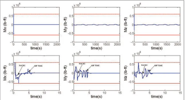
designed ABFTSMC scheme proposed in Wang et al.,37 the simulation results of these two control schemes are given in Figures 4–6 for comparison.
Both these control strategies (RACBC [robust adap-tive constrained backstepping control] and ABFTSMC [adaptive backstepping finite time siliding mode con-trol]) can handle input constraint effectively. It is worth pointing out that under the two controllers, saturation occurs during the transient state phase. After this phase,
Figure 4. Time history of attitude angle tracking of RACBC and ABFTSMC.
control inputs are within their limits. Compared to the ABFTSMC scheme, the proposed RACBC scheme at least has two advantages. First, the saturation time of control input is shorter than that of ABFTSMC, which implies that the designed controller has a higher ability of handling input constraint under model uncertainty and external disturbances. Second, although the settling time of attitude angle is a little longer than that of ABFTSMC, it has the better dynamic process of atti-tude angle tracking.
Conclusion
The attitude controller is designed for RLV in consid-ering input constraint, model uncertainties, and exter-nal disturbance. The stable tracking of the attitude angles is assured by the proposed robust adaptive constrained backstepping controller; simultaneously, the input constraint is tackled effectively. The auxili-ary system is introduced for coping with input con-straint. Besides, the uncertainty generated by the model simplification is estimated and compensated via the high-order robust term. The unknown bound of lumped uncertainty, including the external distur-bance and the uncertainty, is estimated by the robust adaptive law. The ‘‘explosion of terms’’ problem is eliminated through the second-order filter. Based on the Lyapunov theory, the stability of the closed-loop system is analyzed. Simulation results show that the presented controller has reliability of control for RLV. Future research plans will focus on that the control torque is transformed to control rudders. In
this article, the effectiveness of the designed control schemes is evaluated in MATLAB/Simulink environ-ment. In further research, using a real-time interface, the designed control schemes will be carried out under MATLAB/Simulink and runs on the DSPACE sys-tem, which is equipped by a power PC processor.
Acknowledgements
The authors would like to greatly appreciate editor and all reviewers for their comments, which are very helpful for improving our article, as well as the important guiding signifi-cance to our researches.
Declaration of conflicting interests
The author(s) declared no potential conflicts of interest with respect to the research, authorship, and/or publication of this article.
Funding
The author(s) disclosed receipt of the following financial sup-port for the research, authorship, and/or publication of this article: The research of this article was funded in part by The National Natural Science Foundation of China (61503323, 61203012, 51102205), The First Batch of Young Talent Support Plan in Hebei Province, The Youth Foundation of Hebei Educational Committee (QN20131092), China Postdoctoral Science Foundation (2015M571282), The Young Teachers Independent Research Program of Yanshan University (2015M571282), and The PhD Programs Foundation of Yanshan University (B928), Qinhuangdao Science and Technology Project (201502A178).
References
1. Mathavaraj S, Halbe O and Padhi R. Robust control of a reusable launch vehicle in reentry phase using model following neuro-adaptive design. In: AIAA guidance, navigation, and control conference, Toronto, ON, Canada, 2–5 August 2010, paper no. AIAA 2010-8312. Reston, VA: AIAA.
2. Smith R, Ahmed A and Hadaegh F. The design of a robust parametrically varying attitude controller for the X-33 vehicle. In:AIAA guidance, navigation, and control conference and exhibit, Denver, CO, 14–17 August 2000, paper no. AIAA-2000-4158. Reston, VA: AIAA. 3. Georgie J and Valasek J. Evaluation of longitudinal
desired dynamics for dynamic inversion controlled gen-eric re-entry vehicles. J Guid Control Dynam 2003; 26: 811–819.
4. Zhu JJ, Hodel A, Scott A, et al. X-33 entry flight con-troller design by trajectory linearization: a singular per-turbational approach. In: American astronautical society guidance and control conference, Breckenridge, CO, 30 January–4 February 2001.
5. Stott JE and Shtessel YB. Launch vehicle attitude con-trol using sliding mode concon-trol and observation tech-niques.J Frankl Inst2011; 349: 397–412.
6. Lam QM, Krishnamurthy P and Khorrami F. Enhancing flight control system performance using SDRE based controller as an augmentation layer. In:AIAA guidance, navigation, and control conference, Chicago, IL, 10–13 August 2009, paper no. AIAA-2009-6171. Reston, VA: AIAA.
7. Hu T and Lin Z.Control systems with actuator satura-tion: analysis and design. Boston, MA: Birkha¨user, 2001. 8. Wen CY, Zhou J, Liu ZT, et al. Robust adaptive control
of uncertain nonlinear systems in the presence of input saturation and external disturbance. IEEE T Automat Contr2011; 56: 1672–1678.
9. Perez-Arancibia NO, Tsao TC and Gibson JS. Satura-tion induced instability and its avoidance in adaptive control of hard disk drives.IEEE T Contr Syst T2010; 18: 368–382.
10. Zinnecker A, Serrani A, Bolender MA, et al. Combined reference governor and anti-windup design for con-strained hypersonic vehicles models. In:AIAA guidance, navigation, and control conference, Chicago, IL, 10–12 August 2009, paper no. AIAA-2009-6283. Reston, VA: American Institute of Aeronautics and Astronautics (AIAA).
11. Vaddi SS and Sengupta P. Controller design for hyperso-nic vehicles accommodating nonlinear state and control constraints. In: AIAA guidance, navigation and control conference, Chicago, IL, 10–12 August 2009, paper no. AIAA-2009-6286. Reston, VA: American Institute of Aeronautics and Astronautics (AIAA).
12. Gao Y. Linear feedback guidance for low-thrust many-revolution earth-orbit. J Spacecraft Rockets 2009; 46: 1320–1325.
13. Gao G and Wang JZ. Reference command tracking control for an air-breathing hypersonic vehicle with parametric uncertainties. J Frankl Inst 2013; 350: 1155–1188.
14. Liu YB, Xiao DB and Lu YP. Research on advanced fight control methods based on actuator constraints for elastic model of hypersonic vehicle.Proc IMechE, Part G: J Aerospace Engineering. Epub ahead of print 6 August 2013. DOI: 10.1177/0954410013498072.
15. Sun HB, Li SH and Sun CY. Adaptive fault-tolerant con-troller design for airbreathing hypersonic vehicle with input saturation.J Syst Eng Electron2013; 24: 488–499. 16. Wang F, Hua CC and Zong Q. Attitude control of RLV
in reentry phase with input constraint via robust adaptive backstepping control.Int J Adapt Control. Epub ahead of print 2 February 2015. DOI: 10.1002/acs.2541.
17. Waseem AB, Lin Y and Amezquita SK. Adaptive dynamic surface control of a hypersonic flight vehicle with magnitude, rate and bandwidth constraints. In: Pro-ceedings of the 18th IFAC world congress, Milano, Italy, 28 August–2 September 2011, pp.5341–5346.
18. Waseem AB, Lin Y and Amezquita SK. Adaptive inte-gral dynamic surface control of a hypersonic flight vehi-cle.Int J Syst Sci. Epub ahead of print 15 August 2013. DOI: 10.1080/00207721.2013.828798.
19. Xu B, Huang XY, Wang DW, et al. Dynamic surface control of constrained hypersonic flight models with parameter estimation and actuator compensation. Asian J Control2014; 16: 162–174.
20. Waseem AB, Lin Y and Amezquita SK. Adaptive dynamic surface control of a hypersonic flight vehicle with improved tracking. Asian J Control 2013; 15: 594–605.
21. Zhou YL and Chen M. Sliding mode control for NSVs with input constraint using neural network and distur-bance observer.Math Probl Eng2013; 2013: 904830 (12 pp.).
22. Wang L, Sheng YZ and Liu XD. Continuous time-varying sliding mode based attitude control for reentry vehicle. Proc IMechE, Part G: J Aerospace Engineering 2015; 229: 197–220.
23. Geng J, Shi YZ and Liu XD. Finite-time sliding mode attitude control for a reentry vehicle with blended aero-dynamic surfaces and a reaction control system.Chinese J Aeronaut2014; 27: 964–976.
24. Tian BL, Fan WR and Zong Q. Integrated guidance and control for reusable launch vehicle in reentry phase. Non-linear Dynam2015; 80: 397–412.
25. Tian BL, Fan WR and Zong Q. Real-time trajectory and attitude coordination control for reusable launch vehicle in reentry phase. IEEE T Ind Electron 2015; 62: 1639–1650.
26. Tian BL, Yin LP and Wang H. Finite-time reentry atti-tude control based on adaptive multivariable disturbance compensation.IEEE T Ind Electron2015; 62: 5889–5898. 27. Groves KP, Serrani A, Yurkovich S, et al. Anti-windup control for an air-breathing hypersonic vehicle model. In: AIAA guidance, navigation and control conference and exhibit, Keystone, CO, 21–24 August 2006, pp.1–14. Reston, VA: AIAA.
29. Bollino KP.High-fidelity real-time trajectory optimization for reusable launch vehicles. Doctoral Dissertation, Naval Postgraduate School, Monterey, CA, 2006.
30. BoI¨skovic JD, Li SM and Mehra RK. Robust adaptive variable structure control of spacecraft under control input saturation.J Guid Control Dynam2001; 24: 14–22. 31. Peng CC, Hsue AWJ and Chen CL. Variable structure
based robust backstepping controller design for nonlinear systems.Nonlinear Dynam2011; 63: 253–262.
32. Zhang LX, Gao HJ and Kaynak O. Network-induced constraints in networked control system. A survey.IEEE T Ind Inform2013; 9: 403–416.
33. Wu L, Su X and Shi P. Sliding mode control with bounded L2gain performance of Markovian jump
singu-lar time-delay systems.Automatica2012; 48: 1929–1933.
34. Li CY, Jing WX and Gao C-S. Adaptive backstepping-based flight control system using integral filters.Aerosp Sci Technol2009; 13: 105–113.
35. Chen M, Ge SS and Ren BB. Adaptive tracking control of uncertain MIMO nonlinear systems with input con-straints.Automatica2011; 47: 452–465.
36. Tian BL and Zong Q. Optimal guidance for reentry vehi-cle based on indirect legendre pseudospectral method. Acta Astronaut2011; 68: 1176–1184.