Vol-7, Special Issue-Number5-July, 2016, pp917-921 http://www.bipublication.com
e Research Articl
Design and Simulation of a Three-Phase Electrostatic
Cylindrical Rotary Micromotor
Sanaz Rezvani and Abolghasem Zabihollah
Science and Engineering Department, Sharif University of Technology International Campus,
Kish Island, Iran
ABSTRACT
Nowadays the electrostatic motor finds frequent use in micro-electro-mechanical systems (MEMS) where their drive voltages are below 100 volts. Using moving charged plates in capacitor motors are far easier to fabricate than coils and iron cores. This paper presents a novel design of a three-phase electrostatic rotary motor. It is shown that the angular velocity of the cylindrical type motor is almost 1.8 times greater in comparison with parallel plate type and as the voltage increases the enhancement of slope rate in the angular velocity of the cylindrical type is more tangible compared to the parallel plate type. The effect of changing the gap between rotor and stator on the angular velocity is also studied.
Key words: Cylindrical capacitors, Electrostatic, Micro-motors, MEMS, Design, Angular velocity
1. INTRODUCTION
Since 1980 several kinds of electrostatic motors have been studied and fabricated. Electrostatic motors are introduced as one of the most promising micro-electro-mechanical actuators for some reasons. Firstly, the planar structure in these motors is highly compatible with lithography processes in integrated circuits. Secondly in the micro scale, the electrostatic motors are stronger than electromagnetic actuators because the force per volume ratios of electrostatic actuators increases as their dimension decrease [10,1,3,7]. In modern technology we are facing an increasing demand for MEMS technology. Micromotors and microgenerators are power MEMS systems for energy conversion between mechanical and electrical domains [4]. Various types of electrostatic micromotros have been introduced in the past. Vinhais et al. proposed an electrostatic side drive motor. They demonstrated that the torque increases with larger rotor radius, smaller gap between rotor and stator and bigger rotor teeth
feedback control, a flexural suspension of the rotor is employed in a three-phase rotary stepper micromotor [8].
Even though, manufacturing of the micromotors has received a great deal of attention, there are only a few studies about cylindrical design of electrostatic rotary micromotor. Thus, in this paper, for the first time we proposed a novel cylindrical design for micromotors to increase the angular velocity for high speed applications. To investigate the advantages of cylindrical capacitors, the mechanical characteristics of our proposed design is compared to the conventional parallel plate capacitors. The rest of the paper is organized as follows: in section II the mathematical modeling of cylindrical design is discussed. In the next sections the simulation results for the proposed design and comparison study between two models is presented.
2. MATERIAL AND METHODS
2.1 Mathematical Modeling 2.1.1 Cylindrical Capacitors
In the proposed design for micromotor, cylindrical capacitors are used instead of parallel plate capacitors. Figure 1 depicts a cylindrical capacitor with a solid cylindrical conductor of radius a and chargeq that is coaxial with a cylindrical shell of negligible thickness that has radius ba and chargeq. In this case the lengths of the capacitors
L should be much greater than radiusb, thus we
can neglect the fringing effect of the electric field that occurs at the end of the cylinder [5]. In the following formulation εr is the relative permittivity of the material.
Figure 1 Cylindrical capacitor [5]
Here the material is air, thus εr=1 and
12 0 8.85418 10 F m/
is the vacuum
permittivity. Eis the electric field in the region
a r b . The area of the virtual cylinder with radius r is denoted withA. The remaining parameters are shown in figure 1. The electric charge is calculated as follows [5]:
0 r 0 r(2 )
q EA rL (1)
Thus the electric field is [5]:
0 2 r q E rL
(2)
The potential difference between the two cylinders is calculated by:
0 0
ln
2 2
b
r a r
q dr q b
V Eds
L r L a
(3)(ds dr)
Capacitance is calculated by:
q C
V
(4)
Thus we have:
0 2 ln( ) r L C b a
(5)
Electric potential energy can be expressed as [6]:
2
1 2
U CV (6)
So it can be calculated as:
2 0
1
(2 )
2 rln( )
L
U V
b a
(7)
2.1.2 Driving Force for Pole Misalignments The following equation can be used to derive the electrostatic forces in the direction in which misalignment occurs [6]:
i i U F x
(8) Figure 2 is the schematic model of our proposed
design for the rotary micromotor. The misalignment of the electrodes is in the L
direction, thus by calculating the partial derivative of U with respect to L we obtain:
2 0 ln( ) r L F V b a
L
F is the driving force to rotate the micromotor. In
the primary design there are 6 poles on the rotor and 8 poles on the stator. The rotor poles are connected in an alternating sequence with three distinct electrical phases. Each phase activates one third of rotor poles independently. When a given phase is activated, a voltage difference between the corresponding rotor poles and the opposing stator poles generates an electrostatic force. However the radial component of the electrostatic force acting on the rotor is canceled due to the symmetry, the tangential component generates a global torque. The electrostatic torque tends to realign the poles of the stator and the activated rotor phase[2].
The tangential force Ft j, exerted on a single rotor
pole j can be estimated using the cylindrical capacitor as follows:
2 0 ,
ln( )
r
t j i
F V
b a
(10)
Where Vi is the voltage applied on the associated
phase.
Figure 2 The schematic model of our proposed cylindrical rotary micromotor
2.1.3 Driving Torque for Micromotor Rotation
The electrostatic torque Ti applied on the rotor by
one phase is:
2 0 ,
1 ln( )
n
r
i t j i
j
T F r nr V
b a
(11)By putting Ti I where I is the mass moment
of inertia and is the angular acceleration of the
rotor, the angular velocity of the rotor can be calculated. n is the number of active poles per phase.
2.2 Simulation Characteristics
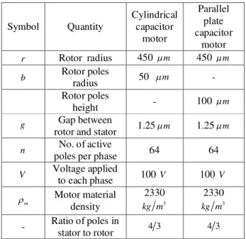
The dimensions of two proposed motors are listed in table 1. To achieve an implicit comparison, the dimensions of proposed cylindrical motor are assumed equal with the parallel plate capacitor motor. For simulating the real function, 192 poles are placed on the rotors. Silicon is chosen for motor material.
Table 1 Values for both motor parameters
Symbol Quantity
Cylindrical capacitor
motor
Parallel plate capacitor
motor
r Rotor radius 450 m 450 m b Rotor poles
radius 50 m - Rotor poles
height - 100 m
g Gap between
rotor and stator 1.25m 1.25m
n No. of active
poles per phase 64 64
V Voltage applied
to each phase 100 V 100 V
m
Motor material
density
2330
3
kg m
2330
3
kg m
- Ratio of poles in
stator to rotor 4 3 4 3
3. RESULTS
While some parameters of the motors are changed the angular velocities of both types of motors are calculated and the result is as below:
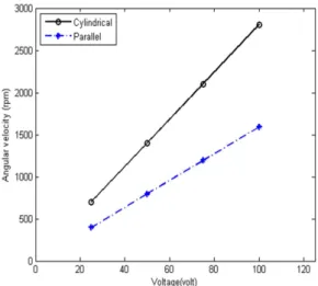
3.1 Effect of Altering the Voltage on Angular Velocity
capacitor formulas. Furthermore, it is apparent that as the voltage increases, the angular velocity of the cylindrical type has a sharper increase compared to the parallel plate type.
Figure 3 Angular velocity versus voltage for both cylindrical type and parallel plate type micromotors
3.2 Effect of Altering the Gap between Rotor and Stator on Angular Velocity
Figure 4 shows that our proposed cylindrical type motor gives us an almost double magnitude of angular velocity compared to parallel plate type motor. It can be seen that as the gap between rotor and stator increases the angular velocity decreases. In this case the rate of decrement is slower in the parallel plate type.
Figure 4 Angular velocity versus gap between rotor and stator for both cylindrical type and parallel plate type micromotors
4. CONCLUSION
A novel design of a three-phase electrostatic rotary micromotor was proposed. The proposed cylindrical type micromotor is compared to the conventional parallel plate type. It was shown that an electrostatic micromotor using cylindrical capacitor produces a larger value of the angular velocity compared to parallel plate capacitors. The angular velocity of the cylindrical type motor is almost 180 percent greater than that of parallel plate type. It is shown that as the voltage increases the angular velocity of the cylindrical type has a sharper increase compared to the parallel plate type. The effect of altering the gap between rotor and stator is also studied. It can be seen that as the gap between rotor and stator is raised the angular velocity decreases and the rate of decrement is slower in the parallel plate type. The advantages of our proposed cylindrical capacitance micromotor make it suitable for design optimization of micromotors for high speed applications, namely microdrilling.
5. REFERENCES
1. Bart, SF., et al. (1988). Design considerations for micromachined electric actuators”, Sens Actuators;14(3) pg. 269–92.
2. Basha, MA., et al. (2007). Design and Fabrication of an Electrostatic Micromotor with a Low Operating Voltage, The 14th International Conference on Solid-State Sensors, Actuators and Microsystems, Lyon, France.
3. Fan, LS., et al. (1988). IC-processed electrostatic micro-motors. Proceedings of the IEEE International Electron Devices Meeting., pg. 666–9.
4. Ghalichechian, N., et al. (2008). Design, Fabrication and Characterization of a Rotary Micromotor Supported on Microball Bearings - Journal of Microelectromechanical systems, VOL. 17, NO. 3, pg 632-642.
6. Hsu, TR. (2008). MEMS & Microsystems: Design, Manufacture, and Nanoscale Engineering, John Wiley &Sons.
7. Jacobsen, SC., et al. (1989). The wobble motor: an electrostatic, planetary-armature, microactuator. Proceedings of the IEEE Micro Electro Mechanical Systems Workshop, pg. 17–24
8. Sarajlic, E., et al. (2010). Three- Phase Electrostatic Rotary Stepper Micromotor with a Flexural Pivot Bearing . Journal of Microelectromechanical systems, VOL. 19, NO. 2, pg. 338-349
9. Sarros, T., et al. (2002). Investigation of Cylindrical and Conical Electrostatic Wobble Micromotors, Elsevier Journal, Microelectronics Journal 33, pg 129-140 10.Trimmer, WSN., et al. (1987). Design
Considerations for a practical electrostatic micro-motor, Sens Actuators;11(2) pg. 189-206.