ISSN 0104-6632 Printed in Brazil
www.abeq.org.br/bjche
Vol. 32, No. 04, pp. 857 - 864, October - December, 2015 dx.doi.org/10.1590/0104-6632.20150324s00003008
Brazilian Journal
of Chemical
Engineering
HYDRODYNAMICS OF PLATE COLUMN FOR
ENZYMATIC REACTIONS OF OIL
A. Dondge and V. K. Rathod
*Chemical Engineering Department, Institute of Chemical Technology, Matunga, Mumbai-40019, India.
Phone: 91-22-33612020, Fax: 91-22-33611020 E-mail: [email protected]
(Submitted: October 2, 2013 ; Revised: September 17, 2014 ; Accepted: October 2, 2014)
Abstract - This work describes the hydrodynamics of a plate column of 5 cm inner diameter and 2.75 m height, operated in a semi-batch manner using an oil-water system especially important for enzymatic catalyzed reactions. The parameters such as dispersed phase superficial velocity, plate orifice size, number of nozzles, nozzle size and plate spacing, affecting the dispersed phase hold up, were investigated. It was observed that the orifice plate produced an uneven change in drop diameter and hence nozzles were used to study the hydrodynamics. The total and dynamic hold ups determined were increased with an increase in dispersed phase superficial velocity, while decreased with an increase in a nozzle size. The total hold up decreased, while dynamic hold up slightly increased with an increase in plate spacing. Correlations obtained are found to be appropriate for the estimation of the total hold up and dynamic hold up.
Keywords: Plate column; Hydrodynamics; Hold up; Oil-water system; Enzymatic reactions.
INTRODUCTION
The current industrial enzymatic processes are usually carried out in a batch reactor, which suffers from various well documented limitations. Although various reactions such as hydrolysis, esterification, transesterification etc. can be catalyzed using acid/ alkali, the use of enzyme as a catalyst has several ad-vantages, including being an environmentally friendly process and mild reaction conditions (Brady et al., 1988; Kimura et al., 1983; Posorske et al., 1988; Van
et al., 1992). This enzyme catalytic process is very
important when the substrate used is highly heat sen-sitive like castor oil. Hydrolysis is one of the im-portant reactions as the products of hydrolysis, i.e., fatty acids, have various applications in industries. Since enzymatic reactions are very slow, taking longer time for completion of the reaction, batch re-actors are not recommended for enzymatic hydroly-sis of oil (Puthli et al., 2006). Further, it is also
858 A. Dondge and V. K. Rathod
is no research paper available mentioning the use of plate columns for enzyme-catalyzed reactions.
The enzyme-catalyzed reactions are interfacial re-actions and the generation of large interfacial area is very important in any reactor. The interfacial area in a plate column depends on the dispersed phase hold up and drop sizes which further depend on various geometrical and operating parameters. Most of the work reported on the sieve plate column is dedicated to conventional liquid-liquid extraction or aqueous two-phase extraction systems (Igarshi et al., 2004; Hamidi et al., 1999; Bhawsar et al., 1994; Muthuravi-chandran et al., 1990; Rathod and Pandit, 2009). How-ever there is practically no information available in the literature on the hydrodynamics of a sieve/nozzle plate column for the system like castor oil-water, which has different physico-chemical properties as compared with conventional systems. With the avail-able literature, it is difficult to design a column reac-tor for the enzyme-catalyzed reaction of oil. Thus, there is a need for a systematic study of the effect of design parameters on the hydrodynamic characteris-tics of the sieve plate column that can enable the scale up of this column, especially for enzymatic re-actions. This paper describes the experimental study of the hydrodynamics of a sieve plate column using the castor oil-water system, followed by develop-ment of correlations for estimation of parameters.
EXPERIMENTAL DETAILS
Materials
The two phase system i.e. castor oil–water system was used. The castor oil was purchased from Ashwin Chemicals.
Estimation of Physical Properties
Phase densities were measured using a specific gravity bottle at room temperature (30±2 °C), and viscosities were measured using a Brookfield vis-cometer. The interfacial tension of oil and water was measured using a Tensiometer (Kruss, Model No. K11), by Wilhelmy Ring method at room tempera-ture (30± 2 °C) (Dondge and Rathod, 2012). Table 1 gives the physical properties of the phases used.
Table 1: Physical properties of system.
Viscosity (Pas) Density (kg/m3) Interfacial Tension (mN/m) Water Castor oil Water Castor oil
0.001 0.418 1000 942.5 8.2
Equipment
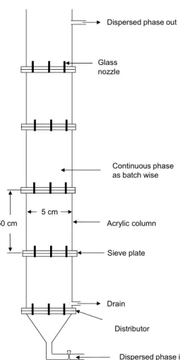
The plate column used for the study consisted of an acrylic column having 5 cm inside diameter and 2.75 m height which was divided into five sections for sieve/nozzle plates and a distributor at the bot-tom. The sections were 50 cm in height. Every sec-tion had two flanges of 60 mm internal diameter and 120 mm outside diameter. Different nozzle plates were made from Acrylic with 120 mm diameter having 7, 14 and 19 nozzles of 0.65 mm, 1.0 mm, 1.5 mm di-ameters and uniform height, arranged on a triangular pitch. A schematic diagram of the plate column, and the top views of sieve/nozzle plates are shown in Figure 1 and Figure 2 respectively. Table 2 gives the design details of the nozzle plates. To study the effect of column parameters on the total hold-up and dy-namic hold-up, the clear continuous phase height in the column was kept at 2.5m. Further, the relation be-tween drop size and terminal rise velocity was studied using the same column without plates (Dhondge and Rathod, 2012), keeping the height of clear continu-ous phase at 2.5 m above the nozzle tips.
Experimental Procedure
Hydrodynamics of Plate Column for Enzymatic Reactions of Oil 859
Dispersed phase in Drain
Sieve plate Dispersed phase out
Acrylic column Continuous phase as batch wise
50 cm
Glass nozzle
Distributor 5 cm
(a)
(b)
(c)
Figure 1: Schematic diagram of sieve plate column. Figure 2: Details of plates: (a) 7 nozzles, (b) 14
nozzles, (c) 19 nozzles; dn = 0.65 mm.
Table 2: Details of plate column design, material of construction: 120 mm diameter with glass
noz-zles, Hc = 2.75 m.
Sr. No Number of nozzles,
N
Nozzle size, dn (mm)
Plate spacing, Z
(m)
Number of plates
1 7 1 2 1
2 7 1 1 2
3 7 1 0.5 4
4 7 1.5 0.5 4
5 7 0.65 0.5 4 6 14 0.65 0.5 4 7 19 0.65 0.5 4
Hold up Measurement
In the sieve plate column, the dispersed phase dis-tributes as drops which move through continuous phase till next plate and accumulates below the plate due to plate resistance. The accumulated drops coa-lesce and a layer of oil below each plate is formed. Thus, based on the dispersed phase distribution, the
dispersed phase hold up is divided in two, i.e., dy-namic hold up and static holdup. Dydy-namic hold up is the ratio of the dispersed volume to the total volume and the ratio of the volume of coalesced layer to the total volume is termed as the static hold-up. The total hold-up is given by the sum of dynamic and static hold-ups. Static hold up contributes significantly to-wards mass transfer, as reported earlier (Rathod and Pandit, 2012), as well as helps in deciding the mini-mum amount of dispersed phase required to operate the column and height of the column. Further, dy-namic hold up requires to determine the interfacial area of contact between the dispersed phase droplets and the continuous phase. The dynamic hold-up, the total hold-up and the static hold-up were determined by the procedure suggested by Bhawsar et al., (1994) from the following equations:
d
t
d
H H
H
860 A. Dondge and V. K. Rathod
4
d i
i d
d
H H h
H
(2)4
i i s
d
h
H
(3)Drop Size in Sieve Plate Column
Interfacial area also depended on the drop size of the dispersed phase and, in the present work, the drop size and terminal rise velocity were obtained from the single drop experiment as described earlier (Dondge & Rathod, 2012). These results were used to estimate the drop size in the sieve plate column.
RESULTS AND DISCUSSION
Drop Size
It is well known that the size and velocity of the drops are important as it decides the performance of a sieve plate column. Although various correlations are available for the drop size and the terminal rise velocity of the drops in the literature, they cannot be used for the present range of physical properties. Therefore, the data reported earlier for single drop experiments was used for determining the average drop size in the sieve plate column (Dondge and Rathod, 2012). The relation between the drop size and terminal rise velocity, obtained from the single drop experiment, is depicted in Figure 3.
70 72 74 76 78 80 82 84 86
0.6 0.7 0.8 0.9 1.0 1.1
Drop Diameter (cm)
T
er
m
inal
r
is
e ve
loci
ty
(
m
m
/s
0.65 mm 1 mm 1.4 mm 1.9 mm 2.4 mm
T
erm
inal
ri
se
vel
o
ci
ty
(m
m
/s)
Figure 3: Variation of terminal rise velocity with drop
diameter.
In the diameter range studied, an increase in the drop diameter resulted in a linear increase in the ter-minal rise velocity. This is because the steady-state terminal rise velocity of the single drops (occur when the buoyant force is equal to the sum of drag force on the drops and weight) varies with the drop diame-ter. Similar results are also reported in the literature (Bhawsar et al., 1996).
Effect of Plate Orifice Size
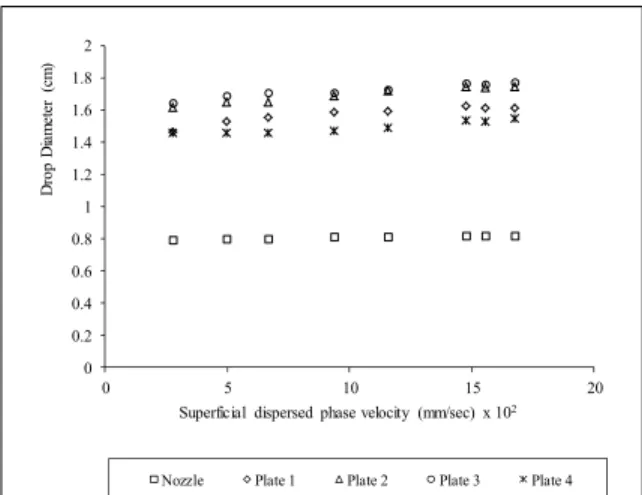
The effect of an orifice on the drop diameter was studied for two different orifices of size 1 mm and 1.5 mm on the plates. This effect was investigated in detail by making a single orifice on each plate for various superficial dispersed phase velocities. The sieve plate column consisted of four plates with a single orifice of desired size and a distributor plate with nozzle of the same size as an orifice. It was ob-served that, at a particular superficial velocity of dis-persed phase (0.16 mm/s), the drop formed due to an orifice became uncontrollably large (nearly double) as compared to the nozzle of the same size. The drop sizes obtained with an orifice of size 1 mm were 1.61, 1.74, 1.77 and 1.55 cm and 1.77, 1.51, 1.73 and 1.61 cm for an orifice of size 1.5 mm from the first, second, third and fourth plate from the bottom, re-spectively, whereas the drop sizes obtained with dis-tributor nozzle sizes of 1 and 1.5 mm were 0.82 and 0.87 mm, respectively, for the superficial dispersed phase velocity of 0.16 mm/s. This uneven change in the drop size with respect to the plate position is shown in Figure 4 and Figure 5. This is probably due to the preferential wetting of the material of the plate by the dispersed phase liquid that results in for-mation of large size globules.
0 0.2 0.4 0.6 0.8 1 1.2 1.4 1.6 1.8 2
0 5 10 15 20
Dr
o
p
Di
am
et
er
(c
m
)
Superficial dispersed phase velocity (mm/sec) x 102
Nozzle Plate 1 Plate 2 Plate 3 Plate 4
Figure 4: Effect of orifice on the drop diameter for
Hydrodynamics of Plate Column for Enzymatic Reactions of Oil 861
0 0.2 0.4 0.6 0.8 1 1.2 1.4 1.6 1.8 2
0 5 10 15 20
D
ro
p
d
iam
et
er
(c
m
)
Superficial dispersed phase velocity (mm/sec) x102
Nozzle Plate 1 Plate 2 Plate 3 Plate4
Figure 5: Effect of orifice on the drop diameter for
nozzle size of 1.5 mm.
An increased in drop diameter resulted in a de-crease in dispersed phase hold up and the interfacial area, which further affects the performance of the column. This problem can be corrected or minimized by using nozzles in place of orifices in the plates. Thus, in order to have a proper control and smaller size of the drop, nozzles were used for the further study. This was also suggested by Treybal (1980) and Mayfield and Church (1952).
Effect of Superficial Dispersed Phase Velocity
In order to study the effect of the superficial dis-persed phase velocity, it was varied in the range of 0.04-0.21 mm/s. The result obtained for the effect of superficial velocity with various plate spacings, noz-zles sizes and numbers of nozzle are shown in Figures 6, 7 and 8, respectively. In all these experi-ments, it is found that an increase in superficial dis-persed phase velocity resulted in an increase in the total hold-up, as well as the dispersed phase dynamic hold-up. The frequency of drop formation increased with an increase in dispersed phase velocity in the single drop experiments. A marginal change in the drop size was observed with an increase in the super-ficial velocity, which results in a marginal increase in a terminal rise velocity of the drop. Due to the mar-ginal change in terminal rise velocity, the number of drops of the dispersed phase in the same volume of the continuous phase increased with the dispersed phase superficial velocity. This resulted in an in-crease in the dispersed phase hold up for higher val-ues of dispersed phase velocities. Similar trends have been reported earlier in a spray column of 2.5 cm diameter for a castor oil-water system (Dondge and Rathod, 2012).
Effect of Plate Spacing
The effect of the plate spacing was investigated in the 5 cm internal diameter column by keeping the number of nozzles (7) and their size (1 mm) constant. The plate spacing was varied from 200 cm to 50 cm by varying the number of plates from one to four. Figure 6 shows the effect of plate spacing on the to-tal hold up and the dispersed phase dynamic hold-up. It was found that the fractional dispersed phase dy-namic holdup decreased slightly, while the total hold-up increased with the decrease in plate spacing (i.e., increase in the number of plates). An increase in the number of plates in a column with the same col-umn height resulted in a decrease in the plate spac-ing. This also gave more coalescence and redisper-sion of the dispersed phase droplets and a greater total volume of coalesced layer below the plates. This was the reason for the increase in the total hold-up with a decrease in plate spacing. The dispersed phase droplets detached away from the tip of the nozzle and the use of a nozzle decreased the effective clear liquid height. Therefore, an increase in the number of plates reduced the height for the travel of drops before coalescence, which led to a slight de-crease in dispersed phase dynamic hold-up. These results are well supported by earlier reported work (Lodh and Rao, 1966; Krishnamurty and Rao, 1968; Rocha et al., 1986).
0 0.002 0.004 0.006 0.008 0.01 0.012 0.014 0.016 0.018
0 0.002 0.004 0.006 0.008 0.01 0.012 0.014 0.016 0.018
0 0.03 0.06 0.09 0.12 0.15 0.18 0.21
D
yna
m
ic
ho
ld
up
T
o
ta
l h
o
ld
u
p
Superficial dispersed phase velocity (mm/s)
Z = 50 cm Z = 100 cm Z = 200 cm
Z = 50 cm Z= 100 cm Z = 200 cm
Figure 6: Effect of plate spacing on the hold up for
different superficial dispersed phase velocities.
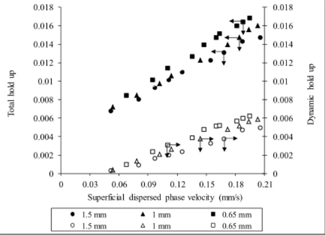
Effect of Nozzle Size
dis-862 A. Dondge and V. K. Rathod
tributor plate and the four plate configurations with 7 nozzles on each plate in the same column of 5 cm diameter. The plates with nozzle sizes varying from 0.65 mm to 1.5 mm internal diameter were used. The effect of nozzle size on the total hold-up, εt, and the fractional dispersed phase hold-up (dynamic hold up), εd, was studied and the results of the experiments are presented in Figure 7.
0 0.002 0.004 0.006 0.008 0.01 0.012 0.014 0.016 0.018
0 0.002 0.004 0.006 0.008 0.01 0.012 0.014 0.016 0.018
0 0.03 0.06 0.09 0.12 0.15 0.18 0.21
D
yna
m
ic
h
o
ld
up
T
o
ta
l h
o
ld
u
p
Superficial dispersed phase velocity (mm/s) 1.5 mm 1 mm 0.65 mm 1.5 mm 1 mm 0.65 mm
Figure 7: Effect of nozzle size on the hold up for
different superficial dispersed phase velocities.
As expected it was observed that a decrease in nozzle size from 1.5 cm to 0.65 mm resulted in an increase in both of the hold-ups for a given dispersed phase velocity. An increase in nozzle size increased the drop size, which led to an increase in the rise ve-locity. Further, at a particular superficial velocity, the number of drops formed with a bigger nozzle also decreased and thus the dynamic hold up decreased. Similarly, an increase in nozzle size increased the cross flow area which reduced resistance to flow of the dispersed phase through it. Therefore, lower hy-drostatic head was required to pass the dispersed phase through the nozzle, i.e., less static layer height. This results in the decrease in dispersed phase static hold up and ultimately the total hold up, as explained by Krishnamurthy et al. (1967). On the other hand, when nozzle size was increased for a constant num-ber of nozzles, the cross sectional area of nozzles also increased, which resulted in requirement of higher superficial velocity to form a jet of the liquid. In other words, jetting velocity increased with an crease in nozzle size, which further led to an in-creased dispersed phase dynamic hold-up.
Effect of Number of Nozzles
Figure 8 shows the effect of the number of noz-zles on the total hold-up and dispersed phase dy-namic hold-up. The number of nozzles was varied from 7 to 19 keeping nozzle size constant (0.65 mm
internal diameter). Trends indicated that the values of both of the hold-ups increased with an increase in number of nozzles. Basically, the dispersed phase flowed through each nozzle in the form of a jet, which is dependent on the superficial velocity of the dispersed phase. The jet further gives drop which break and move upward through the continuous phase. The size of the drop decides the motion of the drop though the continuous phase. As the number of nozzles increased from 7 to 19, the number of drops formed was higher due to more number of drop for-mation points. Since the jet length depends on the velocity of the liquid through the nozzle, an increase in the number of nozzles resulted in a decrease in nozzle velocity for the same superficial dispersed phase velocity. However, all the superficial velocities studied in this work were well below the jetting ve-locity and hence both the holdups increased with the number of nozzles. It was also observed that the meas-urement of continuous phase height was difficult for the higher number of nozzle. This was probably due to the increase in the number of drops at higher number of nozzle that led to a decrease in space and time for coalescence, which resulted in transfer of continuous phase along with dispersed phase in each section.
0 0.002 0.004 0.006 0.008 0.01 0.012 0.014 0.016 0.018 0.02
0 0.002 0.004 0.006 0.008 0.01 0.012 0.014 0.016 0.018 0.02
0 0.03 0.06 0.09 0.12 0.15 0.18 0.21
D
yn
am
ic
ho
ld
up
T
o
ta
l h
o
ld
u
p
Superficial dispersed phase velocity (mm/s)
n=7 n=14 n=7 n=14
Figure 8: Effect of number of nozzles on the hold up
for different superficial dispersed phase velocities.
CORRELATIONS
corre-Hydrodynamics of Plate Column for Enzymatic Reactions of Oil 863
lations were developed by nonlinear least square re-gression analysis for dispersed phase total hold up (εt) and dispersed phase dynamic hold up (εd).
0.5725 0.218
4
0.48 0.956
7.14 10
t
n
We Fr
d Mo
Z
(4)
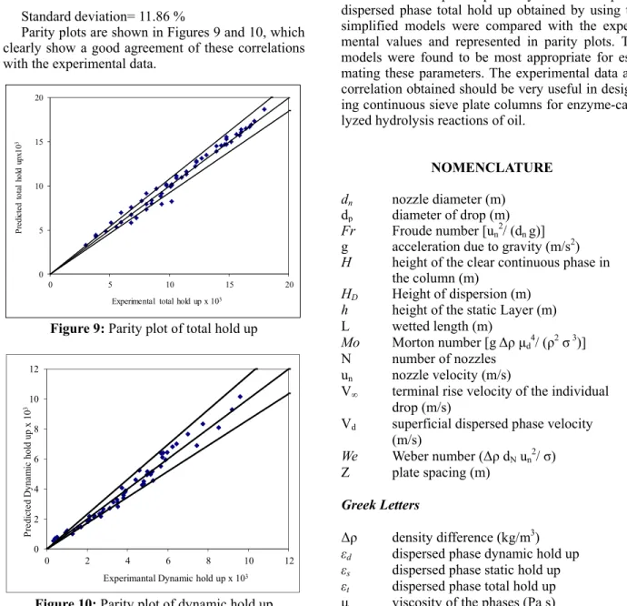
Standard deviation= 4.98 %
1.929 1.115
11
0.281 2.684
7.61 10
d
n
We Fr
d Mo
Z
(5)
Standard deviation= 11.86 %
Parity plots are shown in Figures 9 and 10, which clearly show a good agreement of these correlations with the experimental data.
0 5 10 15 20
0 5 10 15 20
P
re
d
ic
te
d
to
ta
l
ho
ld
u
p
x1
0
3
Experimental total hold up x 103
Figure 9: Parity plot of total hold up
0 2 4 6 8 10 12
0 2 4 6 8 10 12
P
re
di
ct
e
d
D
y
na
m
ic
hol
d
up x 1
0
3
Experimantal Dynamic hold up x 103
Figure 10: Parity plot of dynamic hold up
CONCLUSIONS
The effect of various parameters on hold up was successfully determined in a plate column for the system required for enzyme catalyzed reactions of oil. The type of plate, i.e., orifice or nozzle, had a significant effect on the size of the drop formed, which is higher for an orifice sieve plate as com-pared to a nozzle plate due to wetting. Therefore, it was recommended to use nozzles on the plate instead of orifices. The total hold-up and dynamic hold up increased with an increase in the superficial dis-persed phase velocity in all the experiments, while decreased with an increase in the nozzle diameter. Total hold up increased while dynamic hold up slightly decreased with a reduction in plate spacing. The values of dispersed phase dynamic hold up and dispersed phase total hold up obtained by using the simplified models were compared with the experi-mental values and represented in parity plots. The models were found to be most appropriate for esti-mating these parameters. The experimental data and correlation obtained should be very useful in design-ing continuous sieve plate columns for enzyme-cata-lyzed hydrolysis reactions of oil.
NOMENCLATURE
dn nozzle diameter (m) dp diameter of drop (m)
Fr Froude number [un2/ (dn g)] g acceleration due to gravity (m/s2)
H height of the clear continuous phase in the column (m)
HD Height of dispersion (m)
h height of the static Layer (m) L wetted length (m)
Mo Morton number [g Δρμd4/ (ρ2σ 3)] N number of nozzles
un nozzle velocity (m/s)
V∞ terminal rise velocity of the individual
drop (m/s)
Vd superficial dispersed phase velocity (m/s)
We Weber number (Δρ dN un2/ σ) Z plate spacing (m)
Greek Letters
Δρ density difference (kg/m3) εd dispersed phase dynamic hold up εs dispersed phase static hold up εt dispersed phase total hold up
864 A. Dondge and V. K. Rathod
ρ density of the phases (kg/m3)
σ surface/interfacial tension (N/m) i number of plates
Subscripts
c continuous phase
d dispersed phase
i number of plates
REFERENCES
Bhavasar, P. M., Jafarabad, K. R., Pandit, A. B., Sawant, S. B. and Joshi, J. B., Drop volumes and terminal velocities in aqueous two phase systems. Can. J. Chem. Eng., 74, 852-860 (1996).
Bhawsar, P. M., Pandit, A. B., Sawant, S. B., Joshi, J. B., Enzyme mass transfer coefficient in a sieve plate extraction column. Chem. Eng. J., 55, B1-B17 (1994).
Brady, C., Metcalfe, L., Slaboszewski, D., Frank, D., Lipase immobilized on a hydrophobic, micro-porous support for the hydrolysis of fat. J. Am. Oil. Chem. Soc., 65, 917-921 (1998).
Dhondge, A. S., Rathod, V. K., Hydrodynamics of spray column for enzymatic reactions of oil. Chem. Eng. Res. Des., 90(7), 870-876 (2012). Hamidi, A., van Berlo, M., Luyben, K. Ch. A. M., van
der Wielen, L. A. M., Flooding characteristics of aqueous two-phase systems in a countercurrent sieve-plate column. J. Chem. Technol. Biotechnol., 74(3), 244-249 (1999).
Igarashi, L., Kieckbusch, T. G., Franco, T. T., Xy-lanase mass transfer studies in aqueous two-phase systems using spray and sieve plate columns. Bioprocess Biosyst. Eng., 26(3), 151-157 (2004). Kimura, Y., Tanaka, A., Sonomoto, T., Nihira, T.,
Fukui, S., Applications of immobilized lipase to hydrolysis of triacylglyceride. Eur. J. Appl. Mi-crobial. Biotechnol., 17, 107-112 (1983).
Krishnamurthy, R., Jagannadha Rao, R., Venkat Rao, C., Effect of hole diameter on mass transfer rates in perforated plate extraction towers: Pegasole-butyric acid-water system. Indian J. Technol., 5, 271-275 (1967).
Laddha, G. S., Kirshnan, T. R., Vishwanathan, S., Ve-dian, S., Degalessan, T. E., Hoelscher, H. E., Some performance characteristics of liquid phase spray columns. AIChE J., 22, 456-459 (1976).
Lodh, B. B., Raja Rao, M., Mass transfer efficiency in perforated plate extraction towers. Indian J. Technol., 4, 163-166 (1966).
Mayfield, F. D., Church, W. L., Liquid-liquid extrac-tor design. Ind. Eng. Chem., 44, 2253 (1952). Muthuravichandran, B., Degaleesan, T. E., Laddha,
G. S., Hydrodynamics and mass transport in sieve-plate extraction columns. Indian J. Technol., 27(3), 125-139 (1989).
Posorske, L. H., Lefebvre, G. K., Miller, C. A., Han-sen, T. T., Glenvig, B. L., Process consideration of continuous fat modification with an immobi-lized lipase. J. Am. Oil. Chem. Soc., 65, 922-926 (1988).
Puthli, M. S., Rathod, V. K., Pandit, A. B., Enzymatic hydrolysis of castor oil: Process intensification studies. Biochem. Eng. J., 31(1), 31-41 (2006). Rathod, V. K., Pandit, A. B., Enzymatic hydrolysis of
oil in a spray column. J. Mol. Catal. B, Enzym., 67 (1-2), 1-9 (2010).
Rathod, V. K., Pandit, A. B., Effect of various addi-tives on enzymatic hydrolysis of castor oil. Biochem. Eng. J., 47(1-3), 93-99 (2009).
Rocha, J. A., Humphrey, J. L., Fair, J. R., Mass trans-fer efficiency of sieve tray extractors. Ind. Eng. Chem. Process. Des. Dev., 25, 862 (1986).
Treybal, R. E., Mass Transfer Operation. McGraw Hill, New York, pp. 477-541 (1980).