CFD Analysis Of Straight Ventilated Disc Brake
Nikhil K, Sharan Chandran M*, M.Tech CAD/CAM, VIT University, Vellore
*Asst. Professor, SMEC, VIT University, Vellore
ABSTRACT
Brakes are the key pieces of a vehicle that plays an active role in safety and performance of the system. The study of aerodynamic cooling of a disc brake in real working condition of vehicle is important in present situations. Brake discs get very hot quickly, so it should be dissipated properly through different modes of heat transfer. Contributions of these heat transfer modes are different in different type of problems. The cooling transfer rates are different in vane surface and frictional surface of a disc brake. Also the temperature varies in each small interval of braking time. So a transient problem simulation is important to study the cooling of a disc brake when a vehicle decelerates from a particular speed. ANSYS CFX tool is used for the simulation of this transient problem. Keywords - CFD; ANSYS CFX; Straight Ventilated Disc Brake; Transient analysis.
I.
INTRODUCTION
The evolution of brakes has been impressive, and has included many new technologies throughout the years. In all new developments to the brake system, the number one priority is to improve auto safety and efficiency. Since the earliest automobiles, several methods of braking have been used. As the history of brakes progressed, each new system was built using the concepts used to design its predecessor. In the 1800s, the first mechanisms to slow a vehicle’s momentum and prevent motion were tested. Today, over 100 years later, the braking system has evolved into a complex device designed to adapt to different road conditions. These brakes functioned as a mechanism of changing types of energy. As we know when you apply a brake for a particular moment the pads/shoes that press on the respective brakes disc and drum the energy is to be converted from kinetic energy to thermal or heat energy. In order to balance the absorbed heat energy, the heat should be dissipated in proper way, called heat dissipation management. The cooling of the brakes rotor then started by dissipating heat in proper modes of heat transfer. From the early drum brakes to modern day discs, brake system evolution has improved safety and reduced the risk of car crashes across Canada and the globe. With the goal of creating safer conditions, innovators over the years have brought new technologies to the braking system, improving upon this original idea.
1.1. Disc Brake
In most of the modern cars today, disc brakes are used on the front wheels and in most cases also on the rear wheels. The purpose of the disc brake is to decelerate the vehicle by transforming the kinetic energy of the car into thermal energy using
the friction between the brake disc and the brake pads. The driver decides when to decelerate the vehicle by pushing the brake pedal which determines the brake fluid pressure inside the hydraulic circuit pump is instead often used. Compare to drum brakes disc brakes are having higher order of magnitude at braking of the vehicle.
For most of the cases disc brakes are placed on front wheels because the reason that mentioned above. But in the cases of some sportier vehicle it is used in rear part also. The friction is generated in the location of point of contact of brake pads and rotor, and because of this a mechanical moment developed that also resists the further turning of the brake rotor.
Fig.1.1 Disc brake system
The disc brakes consist of a rotor and caliper at each wheel, while apply braking more fluid comes into action and piston get displaced and caliper push the brake pads and the pads press against the rotor surface. Brake fade is an important phenomenon that is harmful to the brake. In older period which was a common in vehicle. If we come down from a hill with a vehicle the brakes of the vehicle will get heated normally, by keeping the foot on brake again the pads
still hot and no more way to cool it off. As we know for every brake pads some friction material is there for the proper braking action, the resin that holding the material starts evaporating along with friction material and form a layer of gas that further comes as a problem for the next braking. Compare to older cars newly made vehicles are having less out gassing still forming brake fade, this is because our brake pads are of too hot condition as discussed earlier. Then the pads transfer this heat into the caliper because the rotor is already heated, consequently the brake fluids get boiled. So inside the brake fluid bubbles are formed. As we know the brake fluid is not compressible as air, so no proper braking is possible. Researchers are carried both experimental and numerical works in very early period. Limpert [1975] already performed experiments that show the contribution of radiation in the heat dissipation is negligibly small compare to other. He pointed that radiation contributes to less than 5% of the total heat transfer [5] at normal braking conditions. Voller [2003] also performed some experimental analysis and he found that from the mode of heat transfer conduction has not much significance in high speed condition it effectively comes only when the lower speed conditions. Then mass flow rate investigation has been carried out by some researchers and they formulated some results regarding the effect of mass flow rate in cooling behavior during the braking conditions. For this reason, the brake disc is often considered as a centrifugal blower with the inner channels shaped like the blades of an impeller. The researchers are also carried out experimental and numerical analysis for stating the performance of the air flow with innovative designs thus made the effect mass flow rate. Barigozzi [2002] also done an experiment with two types pin and blade configurations [2] and found multiple pin configuration is better for higher turbulent intensity because of the flow complexity in the passage. He also pointed that the mass flow rate of both configurations were linearly proportional to the rotational speed. Arthur Stephens [2006] found the airflow around the rotor experimentally by the brake check facility[1] and also done the analysis with solid disc brake .O.F.P Lyons, D.B Murray and A. Torrance[2008] carried out the investigations with the help of natural air jets and found the cooling of brake disc. Prevec, M; Lerher, T.; Potre, I.& amp; Vranesevie, D."[2010] found the wall heat transfer coefficient of forty one vanes disc by changing the vehicle speeds. Mesut Duzgun [2012] has done an investigation on thermal behavior of disc brakes in terms of thermal stresses with finite element analysis. Mass flow rate has been one of the main factor that should be considered while developing a brake design for better internal cooling performance. In order to avoid the formation of excessive heating a brake disc
should cool as fast as possible. For this reason, the brake disc is often considered as a centrifugal blower with the inner channels shaped like the blades of an impeller. Many researchers have investigated the flow phenomenon through the rotor passage both experimentally and numerically and have suggested some innovative mass flow rate improvement designs[3]. So a disc brake rotor should be considered as a centrifugal impeller which main purpose is to translate energy from the pump/rotor to the air being pumped by accelerating the fluid outwards the center of rotation.
II.
PROBLEM DEFINITION
The problem is described as a car is decelerated from 100kmph to 0kmph with initial temperature 400C and air is flowing with a velocity of 11 m/s around the vehicle. The one cycle of process requires 35 sec.
So while applying the brake, the rotor is decelerated and the heat is generated, this generated heat is absorbed to the rotor. Not complete heat is absorbed to the rotor; some amount will be dissipated to the surrounding air. Since heat absorbs to the rotor so in order to balance the process heat should be dissipated for the cooling of the rotor. The dissipation heat management is contained with three modes of heat transfer. As per the literature survey researchers are already found that the contribution of convection [4][5][8] in the heat dissipation is greatly high compare to other contributor like conduction and radiation. We are formulated the problem by considering the brake disc model with ventilation. From literature survey it has been seen that ventilation plays an important role in increasing the cooling rate [4].
III. .MODELLING
Fig.3.1 Full Rotor model
Fig. 3.2 Recreated model for CFD analysis
The actual CAD model of the disc brake rotor was of complex type. This model is not fit for the CFD analysis, since we are considering the flow effective region of the body. As we know the actual CAD model consists of points, curves, nuts and bolts region, stampings etc. These are unwanted things for our case. So we recreated the model by removing those unwanted parts or region that does not have any role in our problem. Assumed pad area is considered for giving the heat source for the problem. It is created in design modeler of CFX by using the normal case of 450 and arc tool. The created pad area was found as .00417 m2 .
DOMAIN CREATION
For the fluid flow definition and the formulation of the problem we are created useful mathematical domains. Fluid domains are the regions which is useful for defining the direction of flow and also for determining the boundary details. The fluid domain created in the shape of cylinder. Cylindrical enclosure is created and the distance from one side to rotor is shorter than distance from other side. The one side of the cylinder was used as inlet for the fluid flow and other side was outlet region. The cylindrical enclosure is created in CFX design modeler by using Boolean-subtraction operation.
Fig 3.3 Fluid domain created
IV.
MESHING
Meshing is done in ANSYS CFX and used the global mesh with the help of automatic method. We are done a tetrahedral unstructured volume mesh.
The model is complicated with curve geometry, so we can't go for hexagonal type of mesh. The unstructured mesh method is more automated than any other and therefore we can reduce the user time of effort.
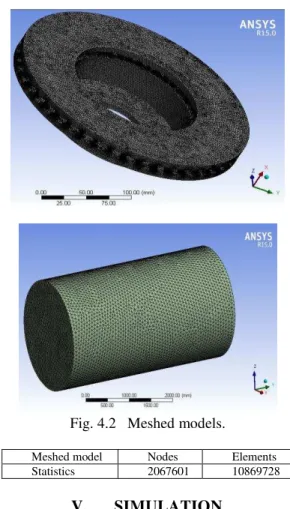
Fig. 4.2 Meshed models.
Meshed model Nodes Elements
Statistics 2067601 10869728
V.
SIMULATION
ANSYS CFX is one of the Computational Fluid Dynamics tool which is used to simulate the problems belong to fluid flow. Engineers are allowed to test system in virtual environment by using ANSYS CFX. This type of CFD tool worked as a scalable program and it can be useful for the simulation of past ship hulls water flowing, gas turbine engines, compressors, combustion chamber, turbines and afterburners, aircraft aerodynamics, pumps, fans, HVAC systems, mixing vessels, hydro cyclones, vacuum cleaners etc. ANSYS CFX is acting as a- general purpose CFD program with high level performance and also particular with its advanced solver technology. Also ANSYS CFX dominates other CFD tool with achieving reliable and accurate solutions quickly and robustly.
Boundary Conditions
perspective of stiffness, friction resistance and cost. The cast iron is commonly used in industry.
Properties of cast iron
SOLID ROTOR: The material of the brake rotor is taken as cast iron and the properties are used from ANSYS CFX data base. Rotation of the rotor considered and the angular velocity of rotation is 83.4 rad/sec. Temperature is of automatic with value type and considered as 313K.
FLUID DOMAIN: Air ideal gas is taken as the fluid. The fluid domain is stationary. Shear stress transport model has taken for the turbulence model. The Fluid domain consists of inlet and outlet for the air flow, opening region. The inside region of the opening is given as moving since the air is flowing around the rotor and through the rotor.
INLET: The inlet of the fluid domain is considered for showing initial airflow towards the rotor. Inlet boundary conditions are given as normal speed air flowing with cycle time. Also the static temperature is given as 313K initially.
OUTLET: The outlet of the domain is atmospheric pressure. Relative pressure is given as 0Pa. Pressure averaging is given as average over whole outlet. OPENING: Opening in stationary fluid domain is of opening temperature 313K.
PAD ROTOR: We also assumed pad region of the rotor, since it was not in the actual rotor model. The Pad region consideration is important for assigning the heat source for the problem. Pad area is considered for two side of the frictional surface and is given as PAD1 and PAD2.
INTERFACE: The whole system consists of Rotor-Fluid interface, Rotor-Fluid-Rotor interface, Rotor-Rotating interface, Rotating Fluid Rotor interface.
Fig 5.1 Boundary conditions.
EXPRESSIONS USED:
Expressions are useful for doing a CFD analysis in CFX. We can give the input values as variables and also we can make some expressions for
the output variable, so that for the case of transient simulation we can get the values of variables at each time steps which ever we want.
Expressions used for the transient analysis. Dt= Time Step Size in Seconds
Heat 1 = Heat Source Value calculated by change in Kinetic Energy
KE = Kinetic Energy Mv = Mass of Vehicle in Kg O = Omega rad/s
ST = Stopping Time in s.
Vact = Velocity for whole Cycle in m/s [considering cooling]
Vd = decreasing Velocity for 6.3 seconds only in m/s The time step size Dt is given as .0001sec, the lower time step size is suitable for getting converged solution easily.
Kinetic energy for each time step is formulated as, KE= 0.5*Mv*(V2old -V2act), Vold is the velocity of the time step before the current position and it is calculated as Vold= Vi-((Vi/ST)*(t-Dt)), Vi is the initial velocity of the wheel, 100km/hr, ST is the stopping time is found as 6.3 sec (calculated from deceleration of the wheel).
A loop is created for determining the Vold for cycle and it is shown in the expression table, it tells if time less than 6.3 seconds then Vold is calculated as from the formula that is given above, otherwise Vold becomes zero. For the case of actual velocity, if Vact less than stopping time then Vact will becomes Vd, decreasing velocity and it found as Vd= Vi-(Vi/ST)*t. Otherwise actual velocity will becomes zero. Angular velocity of the rotor at each time steps will be different so it is given with a formula O=Vact/.333, O is taken for representing the changing angular velocity of the wheel and .333m is the wheel radius. Two plots are given below are showing the problem definition of our problem. The first plot tells about the actual velocity for whole cycle means including the cooling of the brake rotor after comes to a rest at a time 6.3 seconds. The second plot describes the decreasing velocity of the rotor for 6.3 seconds only, means not considering the cooling of the rotor. Heat1 describes the heat source given for the pad 1 , is not necessary whether consider portion is should be come that position
Material Cast Iron
Thermal conductivity(K) 86.5 Wm/K
Density(ρ) 7200Kg/m3
because the rotor model is symmetry and the frictional surface of the rotor has the role of heat flux formation. Heat 1 is provided with an expression that can be seen in above expression table as {
inside()@REGION: Rotor
Pads*.33*KE/(area()@REGION: Rotor Pads* Dt }, this is explained as the one heat source is the pad1 and it is 0.33*KE/area*Dt W/m2 . 0.66 is the brake distribution factor for front wheels, so one wheel it should be 0.33.
VI.
SOLUTION
For the solution case initially we used a converged steady state solution as starting point. If a transient simulation is started from an approximate initial guess the initial transient will not be accurate. As we know the first few time steps may not converge, so a small time step may be needed initially maintain solver stability. For the cyclic behavior the first few cycles can be ignored until a repeated pattern is obtained. Two implicit time stepping schemes are available, first order backward Euler and second order backward Euler. First order is more stable but second order is more accurate. The residual target is given as 1e-4.
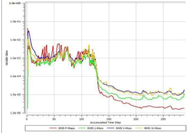
Fig 6.1 iteration
As we know if transient simulation is started from an initial approximate initial guess the initial transient will not be accurate, so initially before going for the transient simulation a converged steady state solution is often used as the starting point. Here the region up to position of 100 accumulated time steps considered as the steady state converged solution and it is used for the starting point for transient simulation.
VII.
RESULTS
The temperature distribution at each time step has been found and is shown below. Here we are provided five plots for the temperature contour. Initially we have given the plots for 0 time step case and we found that temperature distribution is maximum in this case and of 6015K. This is because
during application of braking the wheels are already heated condition and because of the conduction mode of heat transfer the heat transferred from pad to frictional surface became higher and thus temperature distribution through frictional surface became higher. As we know while braking more heat is absorbed by the wheel or brake rotor.
Fig.7.1 Temperature plot for 0 time step
Fig 7.2 .014 sec for 120 time step
When the time step size increased gradually means brake rotor comes to slow, the temperature on the frictional surface and on vanes will become decrease. This is because the action of heat dissipation management. As we know for balancing the cooling rate the absorbed heat should be dissipated properly. The dissipation management for this case considered only is convection mode, because other two modes are not much contributed for this problem.
Fig 7.3 .0196 sec for 128 time step
The part of hub area also showing red hot color, this is because at this region conduction came to account. Due to the conduction with other solid parts of the body of the vehicle the hub get heated more.
Fig 7.5 .0574sec for 288 time step
Cooling rate can be identified from the below graphical representation, The below graph shows the temperature variation on frictional surface of the disc brake at each braking time. The maximum temperature should be at starting time step it was found as 1111 K. As we given the temperature distribution up to braking time 0.042 sec, the temperature at which was found as 382.9 K. Likewise if we go for further time step positions the temperature will fall to some decreased value, thus cooling down occurs and vehicle slows down.
Fig 7.6 Cooling rate of frictional surface of the disc brake rotor
Fig 7.7 Cooling rate on vanes of the disc brake rotor Since we can have only three modes of heat transfer and because temperature is not that much high we cannot consider radiation, so left with conduction and
convection, whatever heat is evolving it is because of conduction that conduction is taking place from pad areas to selected area of outer surface of discs only. But dissipation of heat is happening because of convection may be free or forced convection. The equation used for the conduction heat transfer is Qcond= Kv*Apad*(Told-Tnew)/dx, where Kv is the conduction coefficient for each braking time, Apad is the pad area for one rotation (considered one quarter region pad area and multiplied with 4), Told and Tnew are temperature of the old and new time step, dx is the thickness of the rotor. Similarly Qconv= h*SA*(Told-Tnew), where h is the convectional heat transfer coefficient and SA is the total surface area of the brake rotor since heat convected through the surface area of brake rotor.
By equating the heat evolved on the brake rotor because of the pad contact and the heat dissipation through the convection we got the convectional coefficient for both rotor surface and between vanes separately. Graph shows hv as heat transfer coefficient between vanes. It was found that a very little difference in the case of cooling heat transfer coefficient of both cases. From CFD simulation results we found the cooling transfer coefficients for disc brake on between vanes and frictional surface separately.
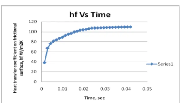
h was found as, heat transfer coefficient h= Q/(SA*(Told-Tnew)), so for each time step we got different heat transfer coefficient but almost close to each other, the variation was because of the changing temperature variation at each braking time.
Average cooling heat transfer coefficient between vanes was found as, hv= 98.15W/m2K
Average cooling heat transfer coefficient on frictional surface found as hf= 98.14906W/m2K
Fig 7.9 Heat transfer coefficient on frictional surface of the disc brake rotor versus time.
VIII.
CONCLUSION AND FUTURE
WORKS
CONCLUSIONThe effective cooling of a disc brake system has been found from a real working condition of a vehicle. We have found from literature survey that the contribution of conventional heat transfer dominates other two types. The conduction heat dissipation also we should consider to understand the hot spot formation since it formed on the frictional surface of the brake rotor. Effect of radiation can be neglected in normal speed case. The temperature distribution on frictional surface and vanes are separately found, and concluded that temperature varied in each braking time and cooling progress. So the cooling heat transfer coefficient for frictional surface and between vanes are found as different and compared. Also calculated the cooling transfer coefficient between vanes and on frictional surface and it was found that they differ slightly because of the temperature variation but they were of increasing order. So we concluded that for the study of effective cooling of a disc brake in a real working condition of a vehicle a time step based analysis is important.
FUTURE WORK
The heat dissipation management we have considered is convectional heat transfer only, not bothered about conduction and radiation modes while simulating the problem. From literature survey we had gotten that the contribution of convectional heat transfer for the dissipation of heat from brake was more than 50% and dominates over conduction and radiation. But we could see the separate contour plot for hub of the brake, showing red hot. Hot spot formation in brakes is nowadays an important phenomenon in the case of brake failure. So in order to understand the hot spot formation and develop full thermal model conduction also we have to consider for the simulation. For this a parallel software running we should consider, external heat software like RADTHERM is useful for this.
IX. ACKNOLEDGEMENT
I can’t conclude this paper by without mentioning a person, Mr. Shyamkumar Jagannath,
CFD engineer, who has been a part of this work and has given great support to approach a Transient simulation problem in an easy way.
X. REFERENCES
[1] Arthur Stephens, Research Thesis:" Aerodynamic Cooling of Automotive Disc Brakes", 2006
[2] Barigozzi, G., Cossali, G.E., Perdichizzi, A., Boden, A. and Pacchiana, P. (2003)“Experimental investigation of the aero-thermal characteristics at the exit of an automotive vented brake disc”, SAE Paper 2003-01-3338
[3] D. Parish and D. G. MacManus, Aerodynamic Investigations of Ventilated Brake Discs, the Institution of Mechanical Engineers, Wilson Applied Science & Technology Abstracts, Vol. 4, pp 219, 2005 [4] G.Puluguandla. (2008), Research thesis:
CFD design analysis of ventilated disc brakes, Canfield University of Engineering. [5] Limpert, R. Cooling analysis of Disc Brake
Rotors. (751014) in Truck Meeting. 1975. Philadelphia, Pa.
[6] Mesut Duzgun, 2012. "Investigation of thermo structural behaviors of different ventilation applications on brake discs", 2012
[7] Neys, A. (2012), Research thesis: In- vehicle brake system temperature model, Chalmers University of Technology, Gothenburg, Sweden, report no. 2012:38.