approaches ingeniously integrate the distinguished features of the symmetry properties of the imaging system and GPU architectures, including block/warp/thread assignments and effective memory usage, to accelerate the computations for ordered subset expectation maximization (OSEM) image reconstruction. The OSEM reconstruction algorithms were implemented employing both CPU-based and GPU-based codes, and their computational performance was quantitatively analyzed and compared. The results showed that the GPU-accelerated scheme can drastically reduce the reconstruction time and thus can largely expand the applicability of the dual-head PET system.
Citation:Chou C-Y, Dong Y, Hung Y, Kao Y-J, Wang W, et al. (2012) Accelerating Image Reconstruction in Dual-Head PET System by GPU and Symmetry Properties. PLoS ONE 7(12): e50540. doi:10.1371/journal.pone.0050540
Editor:Kewei Chen, Banner Alzheimer’s Institute, United States of America
ReceivedMarch 19, 2012;AcceptedOctober 26, 2012;PublishedDecember 26, 2012
Copyright:ß2012 Chou et al. This is an open-access article distributed under the terms of the Creative Commons Attribution License, which permits unrestricted use, distribution, and reproduction in any medium, provided the original author and source are credited.
Funding:This work was supported in part by the National Science Council under grant No. NSC 99-2221-E-002-043-MY3 and NSC 100-2628-M-002-011-MY4, the Taida Institute of Mathematical Sciences, Center for Advanced Study in Theoretical Sciences, and the National Center for Theoretical Sciences (Taipei Office). The funders had no role in study design, data collection and analysis, decision to publish, or preparation of the manuscript.
Competing Interests:The authors have declared that no competing interests exist.
* E-mail: [email protected]
.These authors contributed equally to this work. "These authors also contributed equally to this work.
Introduction
Positron emission tomography (PET) is a proven molecular-imaging technology for a wide range of biomedical researches and applications [1–5]. As its use widens and increases, it has been recognized that both the resolution and sensitivity of PET imaging need to be considerably improved, especially for small-animal imaging applications [6–8]. Dedicated small-animal PET systems that employ High Resolution Research Tomograph (HRRT) detectors can reach good spatial resolution and improved sensitivity. In addition to providing high detection sensitivity and cost effectiveness, planar PET imaging is particularly suitable for imaging thin and small objects like plant leaves. The growing interest in these extended applications also inspired development of PET detectors designed specifically for plants [9,10]. However, this is a challenging goal due to the so-called depth-of-interaction (DOI) blurring that leads to reduced image resolution when thick scintillators or compact scanner geometry are used for increasing sensitivity. To address the issue of depth-of-interaction (DOI) blurring, thick detectors [11–18] and accurate image reconstruc-tion methods based on physical and statistical models [19–23] have been developed. Despite these extended applications and improvements, however, high computation cost presents a significant challenge for such adoptions. Fortunately, commodity
graphics processing units (GPUs) that support massive parallel computing power at a very affordable cost have become available over the past few years and there is astounding growth in the use of GPUs for overcoming the computation challenges in these accurate image reconstructions [24–28]. In this article, we develop a fast GPU-based algorithm for a high sensitivity small-animal PET as outlined in the following two paragraphs.
expensive. It needed to handle a linear system matrix that involved more than 200 million measurements and more than 10 million unknown image voxels. In our initial implementation on a CPU system (four Athlon x64 2.0 GHz PCs), the reconstruction generally took days to complete [33]. This long reconstruction time has prevented the routine use of this high-sensitivity scanner despite of our biologist collaborators’ high interest for using it.
This paper is therefore concerned with developing a GPU-based algorithm to significantly speed up the reconstructions of our high-sensitivity small-animal PET scanner. Our implementation exploits the symmetry properties in our scanner to take advantage of the parallel computing power of a GPU based on the NVIDIA Compute Unified Device Architecture (CUDA). In particular, we propose a shift-invariant LOR-GPU block mapping scheme and exploit the symmetry properties on GPU warp/thread assignments that result in efficient parallelization with reduced memory access cost. We also take advantage of texture memory for fast random data read, shared memory for parallel reduction summation and data reuse, coalesced global memory access, and atomic operation for avoiding race condition. The developed algorithm is applied to simulated and experimental data and yields results with satisfac-tory image quality and substantially reduced computational times. It is mentioned that there are also efforts in speeding up reconstruction by approximating the SRM with a simplified model and factorizing the SRM into component blurring processes [34,35]. Our present implementation does not exploit these approaches but employs a non-factorized, prestored SRM that was accurately calculated by using Monte-Carlo simulations.
In the following sections, we will briefly review the background materials and discuss how to employ GPU computing to accelerate our reconstruction algorithm. A computer-simulation study was carried out to investigate and evaluate the CUDA reconstruction method. The numerical results of which, together with a real-data result, are presented. Finally we conclude the article with a discussion and summary.
Background Review and System Description
We review the GPU technology as well as the design of our dual-head small-animal PET (DHAPET) scanner as follows.
GPU architecture
Our reviews first focus on the GPU architecture related to our implementations. In particular, we use NVIDIA Tesla C2070, code named ‘‘Fermi’’, in conjunction with CUDA, which is an extension of the standard C/C++ programming languages with single instruction multiple threads (SIMT) execution model. Readers who wish to learn more about this subject are referred
Figure 1. A schematic of the architecture of an NVIDIA Fermi GPU. doi:10.1371/journal.pone.0050540.g001
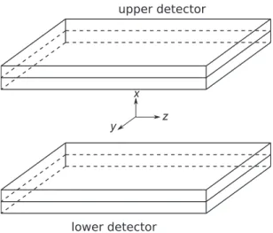
Figure 2. Conceptual illustration of the dual-head PET system with the definition of the coordinate system.The origin is at the center of the active imaging volume, thex-axis is perpendicular to the detectors, and they- andz-axes are along the length and width of the detectors, respectively.
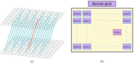
Figure 3. A shift-invariant LOR-block mapping schema.Each shift-invariant LOR shown in (a) is associated with a GPU block shown in (b). Note that only partial LORs are shown in subfigure (a) to avoid cluttering the plot.
doi:10.1371/journal.pone.0050540.g003
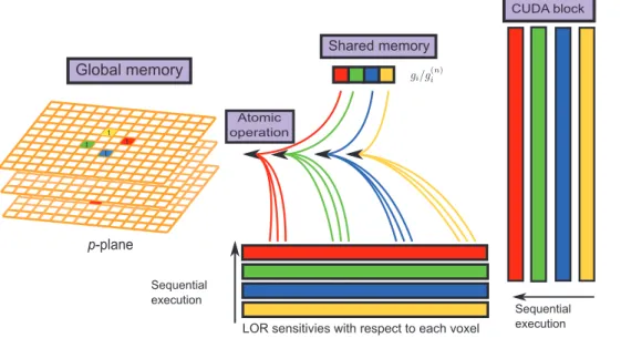
Figure 4. The proposed GPU strategies.(a) The active imaging volume stored in the global memory is bound with the texture memory. The LOR of a particular direction (red) and its symmetric equivalents corresponding to reflection symmetries in y-axis (yellow) and z-axis (blue) and interchangedy- andz-coordinates (green) are shown in the right panel. (b) Each CUDA block contains 128 threads (four warps). These threads multiply the sensitivity functions with the corresponding voxels and store the values in their shared memory for each LOR sequentially. The accumulative summations in the forward projection is performed on the shared memory with parallel reduction summations.
to many monographs, such as [24,36], which cover the subject in-depth.
A Fermi GPU, illustrated in Figure 1 for its processor and memory schema, contains 14 Streaming Multiprocessors (SMs) and Global Memory that can be accessed by all SMs. Globally accessible but read-only Constant Memory and Texture Memory, can be used to accelerate data accesses. The use of Constant and Texture memory can be further accelerated when all threads of a warp (to be explained below) access the same address (i.e., broadcasting) and when memory access patterns exhibit a large degree of spatial locality. Each SM features 32 Scalar Processors (SPs) and a Shared Memory that can be accessed by all32SPs. Each SP also has its own Registers to provide the fastest access to a small amount of data and Instruction Units to increase arithmetic density.
In CUDA programming, the data to be processed on GPU will be transferred from CPU memory to the global memory of GPU first. A CUDA kernel containing a grid of threads is then launched. These threads in the grid are further divided into blocks
that are assigned to execute resources of a Fermi GPU. These blocks are implemented independently and each of which is assigned to one SM for execution. Each block is executed as 32-thread warps. At any given time, the SM concurrently executes the 32 threads in only one warp while holding other warps on wait. Those warps that have operands ready for the next instruction are qualified for execution. The switches among warps are fast. When data sharing is necessary, the threads within a block can communicate with one another via the shared memory of the SM to which that the block is assigned.
Another issue that needs be considered in a multi-threaded program is the race condition, which occurs when multiple threads attempt to access the same piece of memory simultaneously and thereby impact the correctness of the result. To avoid race condition, the Fermi GPU provides atomic operationto guarantee that at any given time only a single thread has access to a given memory. Invoking atomic operation however can slow down the operations.
Figure 5. The schema of the backward projection.A block of 128 threads readgi= X
j’Hij’q
(k{1)
j’ from their shared memory, multiply it with
sensitivity functions and then backproject to the corresponding voxels intersected by each LOR sequentially. doi:10.1371/journal.pone.0050540.g005
Figure 6. A sample coronal slice of the reconstructed image of a real dataset acquired for a healthy adult rat injected with 18-FDG by the DHAPET scanner, by using either(a) the CPU- or (b) the GPU-based OSEM algorithm.The head of the rat was placed at approximately the center of the scanner. The images generated by the two algorithms show negligible differences.
Generally, to maximally utilize the parallel computing power of GPU, one should try to maximize independent task/data/thread parallelism, to maximize arithmetic intensity, to perform more parallelizable computations on the GPU rather on the CPU and to avoid data transfer between CPU and GPU. When data accesses are necessary, we should optimize for coalescing in global memory, for spatial locality in texture memory, and for avoiding bank conflicts in shared memory. However, for a specific algorithm implementations of the general rules are not necessarily a trivial task.
Dual-head small-animal PET scanner
Our DHAPET scanner, illustrated in Figure 2, consists of two HRRT detectors that have a detection-active area of25|17 cm2. The detectors are placed at only*6 cm apart, thereby creating a large detection solid-angle for small animals placed in between [37,38]. Each HRRT detector is comprised of a104|72array of 20|2:1|2:1 mm3double-layered LSO/LYSO crystals having a
crystal thickness and a pitch equal to 20 mm and 2.4 mm, respectively. The scanner remains stationary during imaging. Every pair of two crystals, one from each detector, defines one line-of-response (LOR) and one measurement. Let ~gg~½g1, ,gMT denote the measured data, whereM is the total number of LORs of the scanner, and ~ff~½f1, ,fNT the unknown source image, where N is the total number of image voxels. Let H~fHijg denote the SRM, where Hij is the
probability of an annihilation occurring inside the jth voxel to be detected at theith LOR. The PET imaging model is then given by
Ef~ggD~ffg~H~ffz~rrz~ss, ð1Þ
where~rr and~ssare the mean values of the random and scattered events. In addition, the measurement contains noise and is governed by the Poisson distribution, given by
p(~gg)~PMi~1e{ggigggii =gi!,ggi~EfgiD~ffg: ð2Þ
The imaging model given above by Eqs. (1) and (2) can be solved by a number of iterative algorithms. The focus of the present work is to correct for the DOI blurring; therefore, we will ignore random and scattered events and consider solving the imaging model by using the popular OSEM algorithm. By dividing the LORs of the scanner into a number of disjoint subsets, say Sk,
k~1, ,K, where K is the number of subsets, and given an initial estimate for~ff,say~ff(0),the OSEM algorithm is given by: for n~1,2, ,
~qq(0)~~ff(n{1), ð3Þ
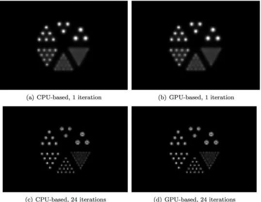
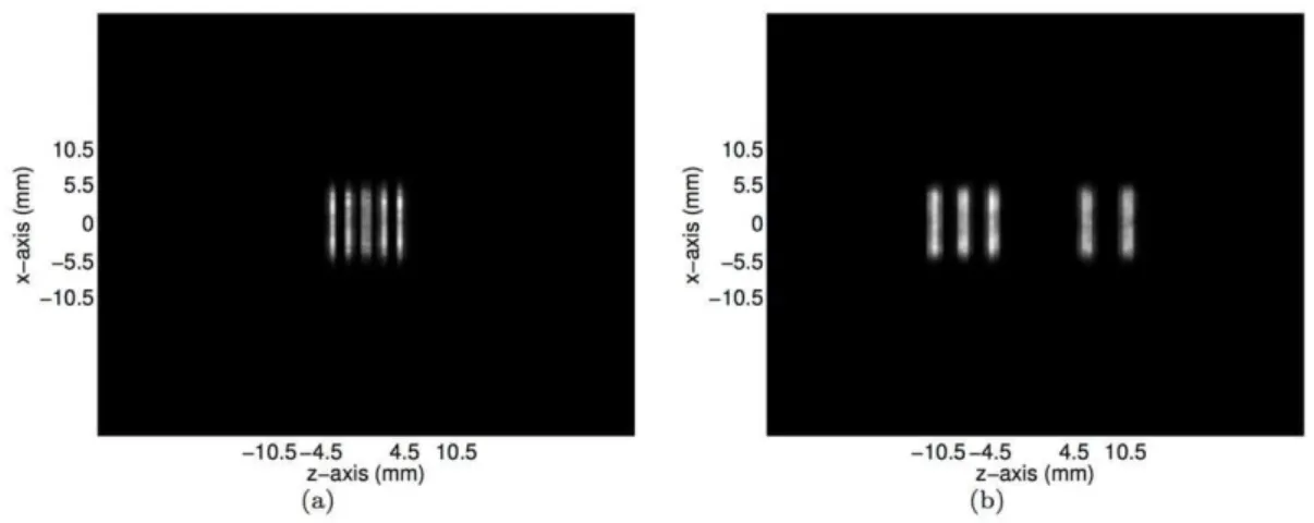
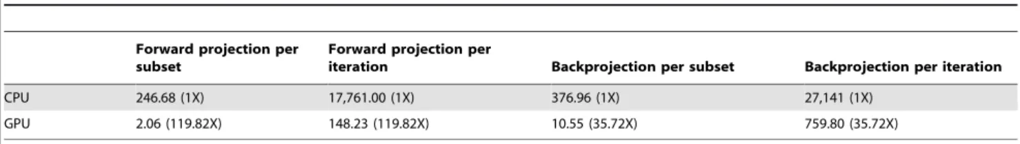
Figure 7. Reconstructed images obtained from simulated data for the numerical micro Deluxe Derenzo phantom by use of CPU- or GPU-based OSEM algorithm after 1 or 24 iterations.The phantom contains 6 groups of rods of different diameters, including 2.4 mm, 2.0 mm, 1.7 mm, 1.35 mm, 1.0 mm, and 0.75 mm. The spacing between the rods in the same group is twice their diameter. The phantom is placed at the center of the scanner with the length of the rods oriented along thex-axis. As shown, the images generated by the two algorithms have negligible differences.
q(jk)~
q(jk{1) P
i[SkHij X
i[Sk Hij
gi
P
j0
Hij0q (k{1) j0
,
j~1, ,N,k~1, ,K,
ð4Þ
~ff(n)~~qq(K), ð5Þ
wherenis the iteration number. Unless mentioned otherwise, we
will use~ff(0)~~11,i.e., all voxels of~ff(0)are set to a constant value of 1. By modeling the DOI blurring in the SRM, the reconstruction algorithm can correct for DOI blurring to yield image of good resolution. Readers are referred to [7] for detailed discussion of the design considerations, image reconstruction, and performance evaluations of the DHAPET scanner.
A particular challenge in implementing the above OSEM reconstruction algorithm arises from the extraordinary dimensions of the SRM. The DHAPET scanner contains more than 224 million LORs and more than 14 million voxels when employing a 6 cm detector spacing and approximately 0.5 mm3 image voxel. As a result, the SRM has more than Figure 8. Intensity profiles of the reconstructed images of the numerical micro Deluxe Derenzo phantom at three selected horizontal positions as identified on the image obtained with 24 iterations.Evidently, small rods of the phantom are much better resolved and show much higher contrast, with 24 iterations.
(2:2|108)|(1:4|107)elements and, by brute force, its
calcula-tion is extremely challenging, if not impossible. In addicalcula-tion, the forward projector (i.e., the operation X
jHijqj) and backward projector (i.e., the operation X
i[SkHijwi and wi~gi=
X
j’Hij’q
(k{1)
j’ ) in Eq. (4), and hence the OSEM algorithm, are also computationally very intensive. In [7], we were able to exploit the symmetry properties of the DHAPET to make it feasible to employ Monte-Carlo (MC) calculations to estimate the SRM including the DOI blurring. However, even with the prestored SRM and exploiting the scanner symmetries to speed up the matrix operations that represent the forward and backward projections, the resulting OSEM algorithm still requires more than 20 hours to run one iteration [33]; consequently, it is difficult to employ the DHAPET scanner for routine small-animal imaging studies. The objective of this work is therefore to exploit GPU computing to massively parallelize, and hence drastically accelerate, the reconstruction algorithm.
Methods for Accelerating the Reconstruction Algorithm by GPU
This section describes our implementation of an OSEM algorithm for the DHAPET scanner on a Fermi GPU. The implementation matches the GPU architecture to the symmetry properties of the scanner and carefully considers the execution order to minimize the slower memory copy operations.
Symmetry properties
The symmetry properties of the DHAPET scanner, which have been previously described in [39], are summarily reviewed below for completeness.
Refer to Figure 2 for the definition of the coordinate system. Although the HRRT detector contains double-layered crystals, we will consider only single-layered crystals for simplicity. A crystal in an HRRT detector can be identified by~cc~(cy,cz),wherecyand
czare the row and column numbers of the crystal, respectively. An LOR, or a crystal pair, can then be identified as(~ccu,~ccl),where~ccu and~cclidentify a crystal on the upper and lower HRRT detectors, respectively. Similarly, an image voxel can be identified by ~vv~(vx,vy,vz),wherevx,vyandvz are the slice, row, and column numbers of the voxel, respectively. The detector response function (DRF)h(~ccu,~ccl;~vv)is defined as the probability for an annihilation taking place in voxel~vvto be detected at the LOR(~ccu,~ccl):Clearly,
h(~ccu,~ccl;~vv)is an element of the SRMHgiven above in Eqs. (1)-(5). Without loss of generality, we can assume the detector to have a crystal pitch equal to D. When choosing the voxel size to be t|(D=D)|(D=D), wheretis the voxel thickness in thexdirection and D is a positive integer, we have the following symmetry properties:
1.Shift invariance: Ignoring boundary condition due to the finite size of the detector, we have
h(~ccu,~ccl;~vv)~h(~ccuz~mm,~cclz~mm;~vvz~mm0), ð6Þ
where~mm~(my,mz)and~mm0~(0,my,mz) withmy,mz[Z.
2.Reflection symmetry: Let Rx, Ry, and Rz denote the operators that negate the x, y, and z components of its operand, respectively, e.g., Rx~vv~({vx,vy,vz): The invariance of the system under reflection with respect to the coordinate axes then implies
Figure 9. The transverse slices of the reconstructed images of the numerical micro Deluxe Derenzo phantom at(a)y~11:7mm and (b)y~{2:7mm as the horizontal lines identified in Figures 8(c)and 8(e), respectively.
doi:10.1371/journal.pone.0050540.g009
Table 1.Computational time for the forward projections in the OSEM algorithm (in seconds) using different GPU algorithms.
Algorithm 1 Algorithm 2 Algorithm 3
Acceleration strategies No symmetry properties, no shared memory
Use symmetry properties Use symmetry properties and memory allocation
Time (s) ,2,417 171.36 111.38
h(~ccl,~ccu;~vv)~h(~ccu,~ccl;Rx~vv), ð7Þ
and
h(~ccu,~ccl;~vv)~h(Ra~ccu,Ra~ccl;Ra~vv), ð8Þ
witha~y,z.
3.Axis interchangeability: Similarly, the system response is invariant when the y- andz-axes are exchanged. Let the operatorSyz swap the y- and z- components of its operand, e.g. Syz~vv~(vx,vz,vy). Then,
h(~ccu,~ccl;~vv)~h(Syz~ccu,Syz~ccl;Syz~vv): ð9Þ
Computation of the system matrix
To obtain the best reconstruction results, it is of great interest to eliminate any pre-reconstruction data interpolation or rebinning. We employed the GATE package [40] to accurately model the detection characteristics of the HRRT detector heads for the dual-head configuration [41]. The GATE package is a public-domain MC simulation package that can accurately model the physical processes and geometric effects [42,43].
In this work, we consider the following settings. Two detector heads with the crystal pitch size of 2.4 mm were positioned at 6 cm apart. We choseD~4andt~0:5mm to obtain a voxel size of0:5|0:6|0:6mm3. We also chose to have 119p-planes and positioned the central plane at exactly the midway between the detectors, thereby makingp-planes symmetric with respect to the reflection about they-zplane (see Symmetry properties section). GATE package generated the point spread function (PSF) for every three seed voxels at each p-plane. In our MC simulation, these seed voxels were filled with a uniform activity of a pair of back-to-back 511 keV c-photons, and a 350–750 keV energy window and a 6 ns coincidence time were assumed. By using the high symmetry properties of the dual-head PET, we can specify
‘‘one’’ LOR or the DRF to compute its response to the uniform activity distribution in the whole imaging space. As a result, to construct the SRM, we only need to compute the detector response functions for 60p-planes, whose index values are within the range of [0 59] and 3 voxels in eachp-plane [7]. The detector head has104|72pixels and was extended to208|208to enable the use of symmetries to be applicable to all elements in the DHAPET system matrix. We exploited the symmetry property and computed the system response matrices, which were stored as sparse matrices to facilitate access in reconstruction. Note that the subject scattering, positron range and photon linearity are not included. Also, the random events were excluded and the scanner dead-time was ignored.
GPU parallelizations
The OSEM algorithm for planar PET can be accelerated by taking advantage of the abundant GPU threads. The computation of forward or backward projection involves multiplication of SRM with a large number of voxels or LORs; therefore, it is natural to assign one thread for each voxel or each LOR. However, such a straightforward GPU parallelization is not optimal as it will yield extremely long reconstruction times. To demonstrate the impact of parallelization schemes, we developed three GPU algorithms using different acceleration strategies. The ideas of the three strategies are presented below.
N Algorithm 1. Forward projection using one thread
block for one LOR.In this straightforward GPU parallelization,
we do not exploit the symmetry properties of DHAPET nor do we use particular memory usage schemes in GPU. The step-by-step procedure is shown below.
1:allocatea(128|1)thread block to handlemth LOR
2: thread[i] reads the corresponding f[i][m] in the mth LOR from the global memory simultaneously
3: thread[i] computess½i~s½izf½i½m h½i½msimultaneously and stores it in its register
4:fori~1,. . .128do
5: proj = proj+s[i] thread[0] sums over 128 threads to obtain forward projection value
Table 2.Computation time of the OSEM algorithm (in seconds) and speedup by the GPU implementation based on the simulated data of the micro Deluxe Derenzo phantom.
Forward projection per subset
Forward projection per
iteration Backprojection per subset Backprojection per iteration
CPU 198.78 (1X) 14,312.00 (1X) 331.57 (1X) 23,873.00 (1X)
GPU 1.55 (128.24X) 111.38 (128.50X) 9.42 (35.20X) 678.27 (35.20X)
doi:10.1371/journal.pone.0050540.t002
Table 3.Computation time of the OSEM algorithm (in seconds) and speedup by the GPU implementation based on the rat dataset.
Forward projection per subset
Forward projection per
iteration Backprojection per subset Backprojection per iteration
CPU 246.68 (1X) 17,761.00 (1X) 376.96 (1X) 27,141 (1X)
GPU 2.06 (119.82X) 148.23 (119.82X) 10.55 (35.72X) 759.80 (35.72X)
symmetric LOR from the texture memory simultaneously 4: thread[i] computess½i½m~s½i½mzf½i½m h½i½m simulta-neously
5: thread[i] stores s[i][m] in the global memory simultaneously
6:end for
N Algorithm 3. Forward projection using one thread
block for multiple reflection and axis symmetric LORs, as well as shared memory for fast data read and write. Because the memory hierarchy in GPU is notably different from that in CPU, this algorithm carefully considers GPU memory structure and suitably uses faster accessing memory like texture memory, shared memory, and parallel reduction scheme. The step-by-step procedure is shown below.
1:allocate N (128|1) thread blocks to handle theN
shift-invariant LORs
2: allocate 128|4 block shared memory for storing partial
sums
3:allocate4|1block shared memory for storing histograms of
4 symmetric LORs 4:form~1,. . .4do
5: thread[i] reads the corresponding f[i][m] in the mth symmetric LOR from the texture memory simultaneously 6: thread[i] computess½i½m~s½i½mzf½i½m h½i½m simulta-neously
7: thread[i] stores s[i][m] in the blocked shared memory simultaneously
8:end for
In the next two sub-sections, we discuss how the symmetry properties can be integrated with GPU and how the GPU memory hierarchy can be efficiently used.
Integration of symmetry properties with GPU architecture
We have reviewed GPU architectures, OSEM algorithm for PET image reconstruction, and symmetry properties in our system. In this section, we will describe our strategies to accelerate image reconstruction: (i) efficient arrangements of blocks, warps, and threads toward algorithmic structure of the OSEM algorithm and the symmetry properties of the DHAPET scanner, (ii) efficient GPU memory usages, and (iii) other efficient implementation considerations. Note that as mentioned above, the SRM is pre-calculated. Even so, the OSEM algorithm is still computationally very expensive due to the large numbers of LORs and image voxels involved. The planar geometry of two 104|72 detector
invariant LORs for a given orientation, as their computations are independent of one another. For example, as conceptually shown in Figure 3, these LORs are shifted from the perpendicular direction by 2 elements in both y- and z- axes in the upper detector so that there are102|70 LORs of such an orientation and thus their forward projections will be determined by the same number of CUDA blocks.
N Exploiting the reflection symmetry and axis interchangeability on warp/
thread assignments leads to a4to(103|71|4)-fold saving for one LOR orientation in the SRM accessing times.
Four-fold and 103|71|4-fold speedups arise from the fact there are 4 most oblique LORs and103|71|4LORs that are shifted from perpendicular direction by 1 element in bothy- and z- axes, respectively. Within each block, the reflection symmetries iny- and z- axes and axis interchangeability betweeny- andz -coordinates were further exploited to yield additional 4 symmetric LORs, which were computed using 128 threads. Figure 4 illustrates the LOR of a particular direction in red and its symmetric equivalents corresponding to reflection symmetries in y- andz-axes and interchangedy- andz-coordinates are depicted in yellow, blue and green, respectively. The application of these symmetry and the shift-invariant properties accounts for a 102|70|4-fold saving in the SRM accessing times for the orientation shown in Figure 4 by using the sensitivity functions common to these LORs of the given orientation.
The exploitation of shift-invariant and reflection symmetry and axis interchangeability for all LORs of orientations amount to 104|72-fold saving in the SRM accessing times.
Efficient memory hierarchy for forward/backward projections
Second, as the bottleneck of the OSEM in the planar PET geometry is the memory bandwidth rather than the floating point arithmetic operations, we emphasize how we can utilize the various GPU memory efficiently in the OSEM algorithm.
N Texture memory binding for fast random data read. In forward
projection, the volume estimatef(n), which is stored in the global memory was bound with texture memory to facilitate random data access for forward projections, as shown in the left panel of Figure 4. Taking advantage of the high efficiency in memory access, the data could be read from texture memory swiftly.
N Shared memory coalescing for parallel reduction summation. The data
related toHij’q(jk’{1)in forward projection is stored in the shared
summa-tions in the forward projection. Our implementation was modified from the CUBLAS isamin function.
N Shared memory for data reuse. In the forward and backward
projections, we employed the first threads of 4 warps (threads 0, 32, 64, 96) within each one-dimensional CUDA block (128 threads) to allocate the histogram data of 4 symmetric LORs to the shared memory. In lieu of assigning a single thread to execute the instruction sequentially or invoking 4 threads in the same warp to access 4 elements that reside on non-contiguous addresses, executing other warps can hide latencies and keep the hardware busy. As indicated by Figure 5, these 4 threads belonging to 4 different warps also allocate the ratios of measured LORs to the projected ones (i.e.,gi=
X j’Hij’q
(k{1)
j’ ) at thek-th subset to their
shared memory for backward projections. Subsequently, these ratios are retrieved and multiplied with the sensitivity functions before backprojecting to the corresponding voxels.
N Global memory without race condition. When writing the forward
results to the global memory, the atomic operator atomicAdd was applied to avoid race condition. Similarly, before the operand of each thread was backprojected to the global memory, atomicAdd operator was also applied to ensure that no race condition occurs.
Third, some other acceleration techniques are remarked.
NBefore the forward or backward projections along each LOR was
carried out, all threads in the block will determine whether the measured histogram data stored in shared memory contain nonzero values. If the data value is zero (i.e., no signal), we assign zero to the corresponding value without further computation.
NWe can avoid memory access by recomputing indices on the fly,
as memory access can take more time than recomputing.
In summary, our GPU acceleration schemes utilized the LOR-based DRF and exploited the abundant threads, spatial locality and other features of the GPU architecture to significantly accelerate both the forward and backward projections. As shown in the next section, the GPU codes achieve significant speedups and thereby largely improve the applicability.
Reconstruction Results
Image reconstruction
A simulated and real datasets were used for evaluation. For the simulated dataset, we implemented a numerical version of the micro Deluxe Derenzo phantom. The phantom was placed at the center of the scanner with the rods positioned along the x -direction (i.e., vertical to the detectors). We first applied the pre-calculated SRM for the scanner to this numerical phantom to generate noise-free measurements. Then, Poisson noise is intro-duced to obtain a simulated dataset containing a total of 1:72|108true events.
The real dataset was obtained by imaging a healthy adult rat (*270 g) by the DHAPET scanner. The rat was placed with its head approximately at the center of the scanner. A bolus injection of*500mCi of 18-FDG via the tail vein was administrated and the rat was scanned immediately after the injection for 30 minutes. Random correction was performed by subtracting the delayed coincidence and removing any resulting negative measurements. The resulting dataset contained about 4:6|108 counts. It was
then normalized for the variation in sensitivity across LORs using measured normalization factors. No correction for subject attenuation or scatter was performed. Figure 6 shows a sample coronal slice of the reconstructed image of the rat dataset by the DHAPET scanner using (a) CPU- and (b) GPU-based OSEM
algorithms, respectively. Both datasets contained coincidence events that only involved the front-layer crystals.
Image reconstruction by use of CPU code was performed on a workstation equipped with an Intel Intel Xeon-E5620 quad-core CPU at 2.40 GHz and 96 GB main memory. An NVIDIA Tesla C2070 GPU with1:15GHz cores and3GB on-board memory is installed in the workstation. The CPU code was compiled by using the Intel C compiler icc. The GPU code was compiled by using Intel icc version and NVIDIA CUDA compiler [45]. In all compilations, we use optimization level -O3. The same extended matrix and symmetry properties are used for both CPU- and GPU-based approaches.
Both the CPU- and GPU-based OSEM codes have successfully reconstructed the testing images. Visually, and confirmed numer-ically, differences between the images produced by the CPU- and GPU-based OSEM algorithms are negligible, validating our GPU implementation. Figure 7 shows the reconstructed images obtained from simulated data for the numerical micro Deluxe Derenzo phantom by use of CPU- or GPU-based OSEM algorithm after 1 or 24 iterations. As shown, the images generated by the two algorithms have negligible differences. Figure 8 compares the intensity profiles of the micro Deluxe Derenzo phantom after 1 and 24 iterations. As shown, the small rods of the phantom are much better resolved with 24 iterations. However, with the CPU-based algorithm one iteration requires about 20 hours of computation; in routine use, one therefore would be constrained to perform no more than a few iterations and to accept sub-optimal imaging results. To show homogeneity and resolution of the reconstructed images alongx-axis, the transverse slices aty~11:7mm andy~{2:7mm are plotted in Figures 9(a) and 9(b), which correspond to the horizontal lines identified in Figures 8(c) and 8(e), respectively.
Performance evaluations
The choice of algorithms has significant impact on the resulting computational times. To demonstrate such effects, we have performed numerical experiments by using all three algorithms introduced in the sub-section ‘‘GPU parallelizations’’. Table 1 listed the estimated computation times for forward projection corresponding to Algorithms 1, 2 and 3. Algorithm 1 took around 2,417seconds to implement one iteration by computing 1 LOR with one 128|1 thread block. Although the use of symmetry properties in Algorithm 2 can significantly reduce the reconstruc-tion times to 171:36seconds, it is still much longer than the 111:38seconds achieved by Algorithm 3. Further, we implement-ed Algorithm 3 by using both 1 and 128 threads to investigate the impact of thread number. The GPU forward projection time per iteration was found to increase from111:38to3,802:58seconds when the thread number reduced from 128 to 1.
time occupies only4:9%of the total GPU time. This observation suggests that our codes can successfully avoid relatively expensive (compared with data accesses on GPU) data transfer between the CPU and GPU and devote most of it resources in the computation part.
Discussion and Summary
We applied similar acceleration strategies to both forward and backward projections; however, the computation of the latter is considerably longer than the former due to the fact that the data structure of the SRM permits only the LOR-based projections. The excessive computational time results from the random writing to the memory in the backprojection for both CPU- and GPU-based codes. The CPU computational times was, in fact, already shortened because there exist a great deal of LORs in the DHAPET system that are shift-invariant or symmetric in some direction. This unique feature in the panel PET system allows for the direct mapping of parallel LORs to the CUDA block and thread units in GPU to facilitate parallel computing. In addition, the multi-threaded program can be further parallelized by employing multiple GPUs. We have demonstrated that the parallel computing units and GPU memory can be integrated
be generalized to accommodate more scanning geometries. We have applied GPU architecture in our GPU-based algorithm to remarkably accelerate the OSEM reconstruction in our dual-head PET system. Numerical studies of the developed algorithm were conducted to demonstrate the achievable speedup employing the currently available GPU hardware. The multi-threaded units, various memory types and other unique features of GPU can be exploited to expedite image reconstruction drastical-ly. With the substantial speedup by the GPU code, we would be able to routinely employ 10 or more iterations in reconstruction to achieve better image resolution and contrast.
Acknowledgments
The authors are grateful to the referees for their valuable and helpful comments and suggestions.
Author Contributions
Conceived and designed the experiments: CYC WW CMK CTC. Performed the experiments: YJK. Analyzed the data: CYC WW. Wrote the paper: CYC WW. Developed sequential codes: YD. Developed GPU code: YH.
References
1. Gambhir S (2002) Molecular imaging of cancer with positron emission tomography. Nature Reviews Cancer 2: 683–693.
2. Rohren E, Turkington T, Coleman R (2004) Clinical applications of PET in oncology. Radiology 231: 305–332.
3. Morrish P, Sawle G, Brooks D (1996) An [18F]dopa–PET and clinical study of the rate of progres-sion in Parkinson’s disease. Brain 119: 585–591. 4. Herholz K, Salmon E, Perani D, Baron J, Holthoff V, et al. (2002)
Discrimination between Alzheimer dementia and controls by automated analysis of multicenter FDG PET. Neuroimage 17: 302–316.
5. Nestle U, Weber W, Hentschel M, Grosu A (2009) Biological imaging in radiation therapy: role of positron emission tomography. Physics in Medicine and Biologyedicine and biology 54: R1–R25.
6. Moehrs S, Del Guerra A, Herbert D, Mandelkern M (2006) A detector head design for small-animal PET with silicon photomultipliers (SiPM). Physics in medicine and biology 51: 1113–1127.
7. Kao C, Xie Q, Dong Y, Wan L, Chen C (2009) A high-sensitivity small-animal PET scanner: development and initial performance measurements. IEEE Transactions on Nuclear Science 56: 2678–2688.
8. Kwon S, Lee J, Yoon H, Ito M, Ko G, et al. (2011) Development of small-animal PET prototype using silicon photomultiplier (SiPM): initial results of phantom and animal imaging studies. Journal of Nuclear Medicine 52: 572–579. 9. Uchida H, Okamoto T, Ohmura T, Shimizu K, Satoh N, et al. (2004) A
compact planar positron imaging system. Nuclear Inst Meth Phys Res, A 516: 564–574.
10. Weisenberger AG, Kross B, McKisson J, Stolin A, Zorn C, et al. (2009) Positron emission tomog-raphy detector development for plant biology. In: Nuclear Science Symposium Conference Record (NSS/MIC), 2009 IEEE. IEEE, pp. 2323–2328.
11. Bartzakos P, Thompson C (1991) A PET detector with depth-of-interaction determination. Physics in Medicine and Biology 36: 735–748.
12. Moses W, Derenzo S (1994) Design studies for a PET detector module using a PIN photodiode to measure depth of interaction. IEEE Transactions on Nuclear Science 41: 1441–1445.
13. Moisan C, Tsang G, Rogers J, Hoskinson E (1996) Performance studies of a depth encoding mul-ticrystal detector for PET. IEEE Transactions on Nuclear Science 43: 1926–1931.
14. Rogers J, Moisan C, Hoskinson E, Andreaco M, Wiiliams C, et al. (1996) A practical block detector for a depth-encoding pet camera. IEEE Transactions on Nuclear Science 43: 3240–3248.
15. Miyaoka R, Lewellen T, Yu H, McDaniel D (1998) Design of a depth of interaction (DOI) PET detector module. IEEE Transactions on Nuclear Science 45: 1069–1073.
16. Murayama H, Ishibashi I, Uchida H, Omura T, Yamashita T (1998) Depth encoding multicrystal detectors for PET. IEEE Transactions on Nuclear Science 45: 1152–1157.
17. Yamamoto S, Ishibashi H (1998) A GSO depth of interaction detector for PET. IEEE Transactions on Nuclear Science 45: 1078–1082.
18. Astakhov V, Gumplinger P, Moisan C, Ruth T, Sossi V (2003) Effect of depth of interaction decoding on resolution in PET: A simulation study. IEEE Transactions on Nuclear Science 50: 1373–1378.
19. Boning G, Pichler B, Rafecas M, Lorenz E, Schwaiger M, et al. (2002) Implementation of Monte Carlo coincident aperture functions in image generation of a high-resolution animal positron to- mograph. IEEE Transactions on Nuclear Science 48: 805–810.
20. Kao C, Pan X, Chen C (2002) Accurate image reconstruction using DOI information and its implications for the development of compact PET systems. IEEE Transactions on Nuclear Science 47: 1551–1560.
22. Rafecas M, Mosler B, Dietz M, Pogl M, Stamatakis A, et al. (2004) Use of a Monte Carlo-based probability matrix for 3-D iterative reconstruction of MADPET-II data. IEEE Transactions on Nuclear Science 51: 2597–2605. 23. Herraiz J, Espana S, Vaquero J, Desco M, Udias J (2006) FIRST: Fast iterative
reconstruction software for (PET) tomography. Physics in Medicine and Biology 51: 4547–4565.
24. Hwu WMW (2011) GPU Computing Gems Emerald Edition. Morgan Kaufmann Publishers Inc.
25. Okitsu Y, Ino F, Hagihara K (2010) High-performance cone beam reconstruction using CUDA compatible GPUs. Parallel Computing 36: 129– 141.
26. Chou C, Chuo Y, Hung Y, Wang W (2011) A fast forward projection using multithreads for multirays on GPUs in medical image reconstruction. Medical Physics 38: 4052–4065.
27. Murphy M, Keutzer K, Vasanawala S, Lustig M (2010) Clinically feasible reconstruction time for L1-SPIRiT parallel imaging and compressed sensing MRI. In: Proceedings of the ISMRM Scientific Meeting & Exhibition. p. 4854. 28. Wang Z, Han G, Li T, Liang Z (2005) Speedup OS-EM image reconstruction by PC graphics card technologies for quantitative SPECT with varying focal-length fan-beam collimation. Nuclear Science, IEEE Transactions on 52: 1274– 1280.
29. Chatziioannou A (2002) Molecular imaging of small animals with dedicated PET tomographs. European journal of nuclear medicine 29: 98–114. 30. Lecomte R (2004) Technology challenges in small animal PET imaging. Nuclear
Instruments and Methods in Physics Research Section A: Accelerators, Spectrometers, Detectors and Associated Equipment 527: 157–165. 31. Tai Y, Laforest R (2005) Instrumentation aspects of animal PET. Annu Rev
Biomed Eng 7: 255–285.
32. Hudson H, Larkin R (1994) Accelerated image reconstruction using ordered subsets of projection data. IEEE Transactions on Medical Imaging 13: 601–609. 33. Dong Y, Kao C (2007) Reconstruction of a dual-head small-animal PET system: An SVD study. In: Nuclear Science Symposium Conference Record, 2006. IEEE. IEEE, volume 5, pp. 2864–2868.
34. Pratx G, Levin C (2011) Online detector response calculations for high-resolution PET image reconstruction. Physics in Medicine and Biology 56: 4023–4040.
35. Zhou J, Qi J (2011) Fast and efficient fully 3D PET image reconstruction using sparse system matrix factorization with GPU acceleration. Physics in Medicine and Biology 56: 6739–6757.
36. Sanders J, Kandrot EK (2010) CUDA by Example. Addison-Wesley. 37. Kao C, Chen C (2004) Development and evaluation of a dual-head PET system
for high-throughput small-animal imaging. In: Nuclear Science Symposium Conference Record, 2003 IEEE. IEEE, volume 3, pp. 2072–2076.
38. Kao C, Souris J, Cho S, Penney B, Chen C (2006) Initial performance evaluation of a modu-lar, large-area detector PET scanner for small animal imaging. In: Nuclear Science Symposium Conference Record, 2005 IEEE. IEEE, volume 4, pp. 2081–2084.
39. Kao CM, Dong Y, Xie Q (2007) Evaluation of 3d image reconstruction methods for a dual-head small-animal pet scanner. In: Nuclear Science Symposium Conference Record, 2007. NSS’07. IEEE. IEEE, volume 4, pp. 3046–3050. 40. Jan S, Santin G, Strul D, Staelens S, Assie K, et al. (2004) GATE: a simulation
toolkit for PET and SPECT. Physics in Medicine and Biology 49: 4543–4561. 41. Jong H, Velden F, Kloet R, Buijs F, Boellaard R, et al. (2007) Performance evaluation of the ECAT HRRT: an LSO-LYSO double layer high resolution, high sensitivity scanner. Physics in Medicine and Biology 52: 1505–1526. 42. Qi J, Leahy R, Cherry S, Chatziioannou A, Farquhar T (1998) High-resolution
3D Bayesian image reconstruction using the microPET small-animal scanner. Physics in Medicine and Biology 43: 1001–1013.
43. Mumcuoglu E, Leahy R, Cherry S, Hoffman E (2002) Accurate geometric and physical response modelling for statistical image reconstruction in high resolution PET. In: Nuclear Science Sympo-sium, 1996. Conference Record., 1996 IEEE. IEEE, volume 3, pp. 1569–1573.
44. NVIDIA Corporation (2008) NVIDIA CUDA CUBLAS Library.
45. Nvidia C (2007) Compute Unified Device Architecture Programming Guide. NVIDIA: Santa Clara, CA.
46. Wuest F (2005) Aspects of positron emission tomography radiochemistry as relevant for food chemistry. Amino acids 29: 323–339.
47. Alexoff D, Dewey S, Vaska P, Krishnamoorthy S, Ferrieri R, et al. (2011) PET imaging of thin ob-jects: measuring the effects of positron range and partial-volume averaging in the leaf of Nicotiana tabacum. Nuclear Medicine and Biology 38: 191–200.