www.adv-radio-sci.net/9/1/2011/ doi:10.5194/ars-9-1-2011
© Author(s) 2011. CC Attribution 3.0 License.
Radio Science
Remote atomic clock synchronization via satellites and optical fibers
D. Piester1, M. Rost1, M. Fujieda2, T. Feldmann1, and A. Bauch1
1Physikalisch-Technische Bundesanstalt (PTB), Bundesallee 100, 38116 Braunschweig, Germany 2National Institute of Information and Communications Technology (NICT), Tokyo, Japan
Abstract.In the global network of institutions engaged with the realization of International Atomic Time (TAI), atomic clocks and time scales are compared by means of the Global Positioning System (GPS) and by employing telecommu-nication satellites for two-way satellite time and frequency transfer (TWSTFT). The frequencies of the state-of-the-art primary caesium fountain clocks can be compared at the level of 10−15 (relative, 1 day averaging) and time scales can be synchronized with an uncertainty of one nanosecond. Future improvements of worldwide clock comparisons will require also an improvement of the local signal distribution systems. For example, the future ACES (atomic clock ensemble in space) mission shall demonstrate remote time scale compar-isons at the uncertainty level of 100 ps.
To ensure that the ACES ground instrument will be synchronized to the local time scale at the Physikalisch-Technische Bundesanstalt (PTB) without a significant uncer-tainty contribution, we have developed a means for calibrated clock comparisons through optical fibers. An uncertainty be-low 40 ps over a distance of 2 km has been demonstrated on the campus of PTB. This technology is thus in general a promising candidate for synchronization of enhanced time transfer equipment with the local realizations of Coordinated Universal Time UTC.
Based on these experiments we estimate the uncertainty level for calibrated time transfer through optical fibers over longer distances. These findings are compared with the cur-rent status and developments of satellite based time transfer systems, with a focus on the calibration techniques for oper-ational systems.
Correspondence to:D. Piester ([email protected])
1 Introduction
Clock comparisons are one of the essential tasks of interna-tional time metrology, e.g. for the harmonization of nainterna-tional standards, for enabling the interoperability between satellite navigation systems, and for the dissemination of time to the public. As an internationally agreed reference the Coordi-nated Universal Time UTC and, more specific, the under-lying International Atomic Time TAI are computed by the Bureau International des Poids et Mesures (BIPM) by using data from 391 atomic clocks distributed all over the world in 69 different institutes (as of October 2010). Most of them are National Metrology Institutes (NMIs) (Arias and Panfillo, 2009; Circular T).
transfer (TWSTFT) (Kirchner, 1999). It has the advantage that modulated signals are exchanged between two sites, and thus propagate simultaneously through the same medium along the same path, just in opposite direction. This leads to a cancellation of most effects which have an impact on the signal delay, in particular those caused by the propaga-tion through the troposphere and ionosphere. TWSTFT usu-ally employs a geostationary telecommunication satellite as a relay for the signals in space. This limits the choice of lo-cations for ground terminal installations and the operational distance to roughly 10 000 km. An advantage of TWSTFT is that results of clock comparisons are available instantly af-ter a link between two ground sites has been established. No post processing is required as compared to GNSS-based time and frequency transfer.
With these currently operational time and frequency trans-fer techniques, the frequencies of state-of-the-art primary caesium fountain clocks can be compared relatively at the level of 10−15 and time scales can be synchronized with
an uncertainty of one nanosecond. At present experiments for satellite based time and frequency transfer are performed or designed with the aim to reduce the so far achieved un-certainty significantly. For example a new system for time and frequency transfer will be available in 2014: the Atomic Clock Ensemble in Space (ACES) will be installed at the In-ternational Space Station (ISS) revolving as time reference about every 90 minutes around the Earth. Time transfer with an uncertainty of as low as 100 ps will be possible by using the integrated ACES-Microwave-Link (MWL) (Cacciapuoti and Salomon, 2009). Compared to currently operational TW-STFT the ACES MWL uses a broader bandwidth for time transfer signals. Thus also on ground dedicated technolo-gies are needed to supply these new experiments with ultra stable reference frequency and time. Recently optical fiber based techniques show very promising results in both fre-quency and time transfer. Distances from campus solutions (1 km) to about 500 km have been investigated and demon-strated. Distances up to 1500 km are discussed (Piester and Schnatz, 2009a). In this paper the possibility of a combina-tion of these techniques is discussed for the applicacombina-tion of global time and frequency transfer.
2 Comparison of time scales and atomic clocks
Facilities for satellite based time and frequency comparisons are standard equipment in every time laboratory. They are operated in a continuous mode and allow the determina-tion of frequency differences between atomic clocks and phase (time) differences between time scales maintained at these laboratories. The latter requires a dedicated calibra-tion of propagacalibra-tion delay in the equipment involved. Before measuring time differences via optical fibers the involved equipment has to be calibrated as well. In this section we briefly describe the two standard satellite based techniques
for time transfer and finally discuss the achieved results of optical fiber time and frequency transfer based on recently performed experiments.
2.1 GPS time and frequency transfer
GPS signal reception has become the standard tool for time and frequency transfer between time laboratories (see e.g. Piester and Schnatz, 2009a). The GPS maintains a min-imum of 24 satellites, in a way that at nearly each location on Earth more than four satellites are simultaneously visible. On each satellite an atomic clock serves as the onboard ref-erence, which is related to the system time reference. From the onboard reference two carriers are generated and trans-mitted. These signals are phase modulated by two charac-teristic pseudorandom noise codes, uniquely associated with each space vehicle, the so called coarse acquisition and the precise codes. As part of the GPS operation practice the po-sitions of the satellites are precisely known and reported inter alia in the data stream from the satellites (see e.g. Kaplan and Hegarty, 2006). With known distance from the receivers’ an-tennae to the satellites ground-based clocks can be compared to GPS time with a typical precision of 10 ns or 1 ns using the coarse or precise code, respectively. Exchange of the col-lected data between two stations via file transfer enables the a posteriori calculation of the time differences between the two local clocks involved. If the carrier itself is used, the precision is in the range of some 10 ps (Gotoh et al., 2003), but typically subject to unknown absolute offsets.
The precision of operational GPS time and frequency transfer has been improved significantly during the last years. It is characterized by the statistical uncertainty uA
for the techniques “single channel” (4.5 ns), “multi chan-nel” (2.5 ns), “P3” (1.0 ns), and “PPP” (0.3 ns) as entitled by BIPM and is carefully examined by the BIPM and doc-umented in the monthly published Circular T, see e.g. issue October 2010. The accuracy of GPS time transfer strongly depends on the calibration procedure. The long-term insta-bility of signal delays in the equipment making up the link determines the necessity of recalibrations, and on the other hand the accuracy of long-term frequency comparisons. For many links a systematic uncertainty uB of 5 ns has been
stated, reflecting the long-lasting conservative practice. This has been put in question when Esteban et al. (2010) estimated a significantly reduced uncertainty of calibrations using a traveling GPS receiver. Recently this has been refined and uncertainties below 1 ns have been reported by Feldmann et al. (2010). There is still a need for confirmation of such small values, but an uncertainty of 1.6 ns should be feasible. It is clear that these small values foruB can be maintained over
2.2 Two-way satellite time and frequency transfer
TWSTFT is the second satellite based technique which is regularly used for generating TAI. The main advantage of the two-way technique is that unknown delays along the signal path cancel out to first order because of the path reciprocity of the transmitted signals (Kirchner, 1999). At present TWSTFT makes use of established communica-tion satellite services mainly in the Ku-band (10.7 GHz to 14.5 GHz). Time signals are transmitted by relating the phase of a pseudorandom noise modulation on the carrier signal to the one-pulse-per-second input from a clock. A dedicated code is allocated to each transmitting station. The receive equipment correlates the received signal with a local replica of the signal expected from the transmitting site, and deter-mines the time of arrival of the received signal with respect to the local clock.
With currently operational satellite link budget parame-ters, frequency instabilities (in terms of Allan deviation, see e.g. Riley, 2008) following aσy(τ )=10−9(τ/s)−1 law can
be achieved, which enables frequency comparisons at the level of 10−15at reasonable averaging timesτ (Bauch et al., 2006). The precision at an averaging time of 1 s is about 0.5 ns. TWSTFT time comparisons can be performed with an uncertainty of about 1 ns if the internal delays in the ground station equipment are determined by calibration. As an example, for one time link this is usually achieved by circulating a portable reference TWSTFT station to deter-mine the overall relative delay difference between the two local ground stations’ transmit and receive equipment. Such calibrations have been done repeatedly between European stations and between PTB and the U.S. Naval Observatory (Piester et al., 2008). Breakiron et al. (2004) report for a se-ries of intra U.S. calibration campaigns overall uncertainties down to 0.38 ns. On the other hand also values of slightly above 1 ns have been reported for recent European cam-paigns (Bauch et al., 2009) which lead us to conclude that us-ing currently available equipment link uncertainties between 0.4 ns and 1.2 ns are achievable.
2.3 Optical fiber time and frequency transfer
The most recent developments in optical fiber time and fre-quency transfer have demonstrated that a further and signif-icant reduction of uncertainty is possible. Transfer of fre-quency signals on fiber lengths up to more than 100 km have been demonstrated (see e.g. Grosche et al., 2009). The in-troduction of Brillouin amplification for the use in frequency transfer has the potential to bridge more than 250 km without intermediate amplifier stations (Terra et al., 2010). Also very promising results have been achieved for frequency transfer using standard signals for a broader application. We give two examples: a 10 MHz signal as used widely in timing laboratories (Ebenhag et al., 2008) and a 1.5 GHz signal for radio astronomy applications (McCool et al., 2008). Both
approaches demonstrate frequency distributions with uncer-tainties below 10−15.
To cancel long term fiber length variations in time and fre-quency transfer the two-way method for exchanging optical signals has been investigated (Amemiya et al., 2006). Such an approach was initially proposed in the framework of net-work synchronization (Kihara and Imaoka, 1995).
Currently, analysis of time transfer through optical fibers (TTTOF) is investigated by different groups. Stability an-alyzes prove the measurement precision to be at a level of 10 ps (Czubla et al., 2006) or below ( ´Sliwczy´nski et al., 2010). Smotlacha et al. (2010) demonstrated their two-way system using a 740 km link. In our work we have focused on the capability of calibrated time transfer (Piester et al., 2009b) using equipment similar to the TWSTFT scheme de-scribed before. In the two latter systems code division multi-ple access (CDMA) signals are employed and precisions be-low 100 ps and 10 ps, respectively, have been reported. The capability for calibrated time transfer on the level of 40 ps has been demonstrated in our study. A further improvement and the extension to longer distances is discussed in the next section.
3 Calibration and uncertainty evaluation of an optical fiber time transfer link
For the operation of a time transfer link in the strict sense a suitable calibration of the propagation delays is obligatory. Here we describe a procedure which can be executed at a single laboratory before the equipment will be installed at the locations where the systems will be operated. We use the nomenclature of existing literature (ITU-R, 2003; Bauch et al., 2011) and deviate only if necessary. The measurement setup is depicted in Fig. 1. We use in our setup modems which are also used for TWSTFT. Generally, we want to compare two time scales TA(1) and TA(2) generated at differ-ent distant laboratories. The modems’ time-of-arrival mea-surements TW(i)are given by
TW(1)=TA(1)−TA(2)+TX(2)+SP(2)+RX(1), (1) and
TW(2)=TA(2)−TA(1)+TX(1)+SP(1)+RX(2). (2) TX(i)and RX(i) represent the complete internal transmis-sion and receive delay of setup i. SP(1) is the transmis-sion path delay from the local setup (1) to the remote site (2). SP(2) is the propagation delay in the opposite direction through the same fiber. For a single optical fiber connection between two sites we assume complete reciprocity of this part of signal path setting SP(1)=SP(2), and thus
TA(1)−TA(2)=1/2[TW(1)−TW(2)]
FDA
HM-frequency (10 MHz)
DIV
TWSTFT-modem
E/O
O/E
FDA
TWSTFT-modem E/O
O/E
modulated signals
DIV
1pps time reference TA(1)
TA(2)
~2 m indoor fiber loop ~2 m indoor fiber loop
a)
~2 km outdoor test loop ~2 km outdoor test loop
b)
c)
bidirectional optical amplifier bidirectional optical amplifier BABA (2)nn(2)
BA2 BA2
RX(2) RX(2) TX(2) TX(2) RX(1)
RX(1) TX(1) TX(1)
SP(2) SP(2) SP(1) SP(1)
BA BA (1)nn(1) BA1
BA1
Fig. 1.Calibration setup for testing the independence of time trans-fer results from the length of the optical fiber. The two fibers used are depicted as(a)a short fiber and(b)a long fiber. On long distance connections(c)a number of bidirectional amplifiers is inserted into the signal path.
where DLD(i)=TX(i)−RX(i)is the delay difference be-tween the TX path and the RX path of one setup. For accurate time transfer we want to determine the last term in Eq. (3) as the calibration result. For this calibration we use a common clock configuration and adjust TA(1)=TA(2), which leads to
0=1/2[TW(1)−TW(2)] +1/2[DLD(1)−DLD(2)]. (4) The first term is the so called common clock difference CCD(1,2)=1/2 [TW(1)−TW(2)]. It is measured to deter-mine the delay difference between both systems correspond-ing to a calibration value defined as
CALR(1,2)=1/2[DLD(1)−DLD(2)] = −CCD(1,2). (5) For the calibrated time transfer link between the two setups, finally installed at remote sites, we get
TA(1)−TA(2)=1/2[TW(1)−TW(2)] +CALR(1,2). (6) As noted before, a prerequisite for accurate comparisons of remote time scales is the possibility for delay calibration of the whole system. Because the optical fiber length in the final setup is unknown, a calibration test is needed to ensure the independence of the setup from the length of the used fiber which connects both laboratories. For this purpose we con-nected the modems to reference frequency and 1pps (1-pulse-per-second) from signal distribution equipment (FDAs) and pulse generators (DIVs) as illustrated in Fig. 1. The 1 pps cable connectors represent generally the time scales TA(1) and TA(2). Both TTTOF setups were then connected by two fibers which were subsequently exchanged: a 2 m short in-door fiber (Fig. 1a) and a 2 km long fiber (Fig. 1b) buried on the PTB campus. The attenuation of the two optical fibers
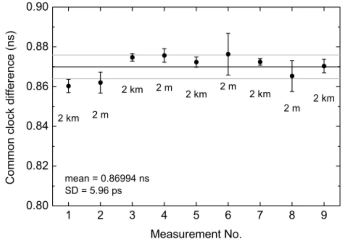
Fig. 2. Display of the sequence of measurements with short fiber loop and long outdoor fiber loop (see Rost et al., 2010). The mea-surements are labeled with the used fiber length. Mean and standard deviation (SD) are depicted as black and gray lines, respectively.
was adjusted to be at the same level by inserting a variable optical attenuator into the bidirectional fiber path SP(i), in order to minimize the impact of receive power dependent de-lay variations in the modems. The optical power was kept constant within±0.1 dB.
The results of measurements CCD(1,2)=1/2 [TW(1)−
TW(2)] when switching over between long and short fibers is depicted in Fig. 2 (see Rost et al., 2010 for details of the ex-perimental setup). The sequence comprises eight switches between the long and the short fiber. The error bars in Fig. 2 represent the standard deviation of single secondly recorded measurements. The standard deviation of the single CCD(1,2) values around the mean is only 6 ps. However, two effects were observed which have to be investigated in more detail in future: variations at the beginning of the sequence might be a result of temperature variations and the higher standard deviation of the measurements with the short fiber may be due to instabilities caused by interference of the op-tical signals partly reflected at fiber connectors. A reduction of interference could be achieved if different optical wave-lengths are used in the local and remote setup. Nevertheless, the small variations of below 40 ps (including error bars) ob-tained under different experimental conditions are promising results to comply with the aim of enabling time transfer with an uncertainty well below 100 ps to supply next generation satellite based time and frequency transfer techniques.
TA(1)−TA(2)=1/2[TW(1)−TW(2)]
+1/2[DLD(1)−DLD(2)] +1/2[dBA(1,2)+dBA2(1,2)
+...+dBAn(1,2)] (7)
where dBAn(1,2) is the delay difference of then-th bidirec-tional amplifier BAn(1)−BAn(2) (see Fig. 1c). The values for dBAn(i)can be determined as follows. The necessary amplifiers for a link are inserted into the calibration setup (common clock TA(1)=TA(2)). From Eq. (7) we get 0=1/2[TW(1)−TW(2)]
+1/2[DLD(1)−DLD(2)] +1/2[dBA1(1,2)+dBA2(1,2)
+...+dBAn(1,2)] (8)
After changing the direction of the first amplifier the mea-surement is repeated:
0=1/2[TW(1)−TW(2)] +1/2[DLD(1)−DLD(2)]
+1/2[−dBA1(1,2)+dBA2(1,2)+...+dBAn(1,2)] (9) Then the direction of each of all amplifiers is subsequently changed:
0=1/2[TW(1)−TW(2)] +1/2[DLD(1)−DLD(2)]
+1/2[−dBA1(1,2)−dBA2(1,2)−...−dBAn(1,2)] (10) We get DLD(1)−DLD(2) from adding Eqs. (8) and (10). We get the differential delay e.g. for the first amplifier by subtracting Eqs. (8)–(9). If we only want to calibrate the total link as a whole, only measurements Eqs. (8) and (10) need to be combined. Thus only the uncertaintiesuof two measurements will contribute to the overall uncertainty
U=√2·u, (11)
if we assume the sameufor both measurements. However, this will not allow the exchange of a single device without loosing the link calibration information. For the calibration of a whole link includingnbidirectional amplifiers one will need n+1 common clock difference measurements. The overall uncertaintyUis in this case
U=√n+1·u. (12)
If we consider aboutu=40 ps for each delay difference de-termination, we expect for a 900 km link with 8 bidirec-tional erbium doped fiber amplifiers an uncertainty of about
U=60 ps following Eq. (11) andU=120 ps after Eq. (12).
4 Summary and outlook
At present three methods exist (or are experimentally evalu-ated) to synchronize remote atomic clocks and time scales on the nanosecond level and below. The results for these time synchronization methods are summarized in Table 1. If one needs a time synchronization at the level of 5 ns or slightly below, GPS is the choice. GPS receivers are rather inexpen-sive compared to the other techniques presented, and their operational performance is almost site independent. Using the so called “all-in-view” data computation approach one can compare two sites regardless where they are located on Earth. Most laboratories maintaining a local realization of UTC use GPS links for their connection to the international network of timing laboratories.
TWSTFT offers a lower calibration uncertainty together with a link stability both at the level of one nanosecond. Beside the superior performance some drawbacks have to be taken into account: the operational distance is limited to about 10 000 km and a geostationary satellite has to be avail-able. It must be equipped with transponders providing the required connectivity in the visibility range of both partici-pating stations. So the establishment of a network is more demanding. Also the number of simultaneous clock compar-isons in a network is limited by the hardware used. TWSTFT ground stations are elaborate and expensive, and furthermore transponder bandwidth and time need to be purchased from the satellite operating agency, resulting in substantial running costs.
Table 1.Achievable calibration uncertainties of time transfer links. The stated uncertainties do not comprise the long-term stability of the calibrated links.
Distance (km) Uncertainty (ns) References
GPS ∼20000 <1.6 to 5 Esteban et al., 2010; Feldmann et al., 2010; Circular T, 2010 TWSTFT ∼10000 ∼0.4 to∼1.2 Breakiron et al., 2005; Piester et al., 2008; Bauch et al., 2009 Optical Fibers ∼1500 <0.1 to 0.2 Rost et al., 2010; this work
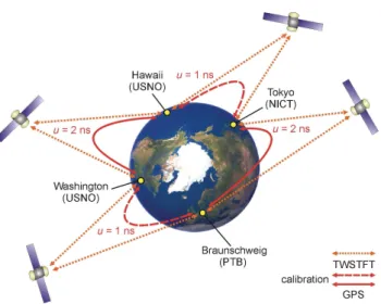
Fig. 3.An example for TWSTFT around the Earth and prospective calibration uncertainties.
A future scenario could be a combination of the presented techniques and might be used for global time comparisons: on shorter distances of several hundred kilometers laborato-ries might be connected via optical fibers, while these clus-ters are connected by intercontinental TWSTFT links and enhanced GNSS time links. The capability for TWSTFT calibrations on the global scale will be tested by circulating reference GPS receivers and mobile TWSTFT stations be-tween the United States Naval Observatory USNO (Washing-ton DC), the National Institute of Information and Commu-nications Technology NICT (Tokyo) and the Physikalisch-Technische Bundesanstalt (Braunschweig, Germany). An example is depicted in Fig. 3. First steps have been done during some hours in 2010 by performing a first TWSTFT test for time comparisons around the world with the inclusion of Telecommunication Laboratories of Taiwan (W.-H. Tseng, private communication, 2010). An operational global link will offer the possibility to test the accuracy of a round trip calibration to better than 4 ns, if the two GPS and the two TWSTFT calibrations’ results will have uncertainties of 2 ns and 1 ns, respectively.
References
Amemiya, M., Imae, M., Fujii, Y., Suzuyama, T., Ohshima, S., Aoyagi, S., Takigawa, Y., and Kihara, M.: Time and Frequency Transfer and Dissemination Methods Using Optical Fiber Net-work, IEEJ Trans. FM, 126, 458–463, 2006.
Amemiya, M., Imae, M., Fujii, Y., Suzuyama, T., Hong, F.-L., and Takamoto, M.: Precise Frequency Comparison System Using Bidirectional Optical Amplifiers, IEEE Trans. Instr. Meas., 59, 631–640, 2010.
Arias, E. F. and Panfillo, G.: International time scales at the BIPM: impact and applications, Proc. 14th International Metrol-ogy Congress, Paris, 2009.
Arias, E. F.: Time scales and relativity, Proc. International School of Physics “Enrico Fermi” Course CLXVI Metrology and Fun-damental Constants, edited by: T. W. H¨ansch et al., IOS Press, Amsterdam, 367–392, 2007.
Bauch, A., Achkar, J., Bize, S., Calonico, D., Dach, R., Hlava´c, R., Lorini, L., Parker, T., Petit, G., Piester, D., Szymaniec, K., and Uhrich, P.: Comparison between frequency standards in Europe and the USA at the 10−15uncertainty level, Metrologia, 43, 109– 120, 2006.
Bauch, A., Piester, D., Blanzano, B., Koudelka, O., Kroon, E., Dierikx, E., Whibberley, P., Achkar, J., Rovera, D., Lorini, L., Cordara, F., and Schlunegger, C.: Results of the 2008 TWSTFT Calibration of Seven European Stations, Proc. European Fre-quency and Time Forum – IEEE FreFre-quency Control Symposium Joint Conference, Besanc¸on, France, 1209–1215, 2009. Bauch, A., Piester, D., Fujieda, M., and Lewandowski, W.:
Direc-tive for operational use and data handling in two-way satellite time and frequency transfer (TWSTFT), Rapport BIPM-2011/01, 2011.
Breakiron, L. A., Smith, A. L., Fonville, B. C., Powers, E., and Mat-sakis, D. N.: The Accuracy of Two-Way Satellite Time Transfer Calibrations; Proc. 36th Annual Precise Time and Time Interval (PTTI) Systems and Applications Meeting, Reston, VA, USA, 139–148, 2004.
Cacciapuoti, L. and Salomon, C.: Space clocks and fundamental tests: The ACES experiment, Eur. Phys. J. Special Topics, 172, 57–68, 2009.
Calhoun, M., Huang, S., and Tjoelker, R. L.: Stable Photonic Links for Frequency and Time Transfer in the Deep-Space Network and Antenna Arrays, Proc. IEEE, 95, 1931–1946, 2007.
Circular T.: monthly publication of the BIPM, URL: http://www. bipm.org/jsp/en/TimeFtp.jsp, December 2010.
Usage of Multi-Channel GPS CV Receivers and Optical Fibers over Distances of About 3 Kilometers, Proc. 38th Annual Pre-cise Time and Time Interval (PTTI) Systems and Applications Meeting, Reston, Virginia, USA, 337–345, 2006.
Ebenhag, S.-C., Hedekvist, P. O., Rieck, C., Skoogh, H., Jarlemark, P., and Jaldehag, K., Evaluation of Output Phase Stability in an Fiber-Optic Two-Way Frequency Distribution System, Proc. 40th Annual Precise Time and Time Interval (PTTI) Systems and Ap-plications Meeting, Reston, VA, USA, 117–124, 2008.
Esteban, H., Palacio, J., Galindo, F. J., Feldmann, T., Bauch, A., and Piester, D.: Improved GPS-Based Time Link Calibration In-volving ROA and PTB, IEEE Trans. UFFC, 57, 714–720, 2010. Feldmann, T., Bauch, A., Piester, D., Rost, M., Goldberg, E.,
Mitchell, S., and Fonville, B.: Advanced GPS Based Time Link Calibration with PTB’s New Calibration Set-Up; to be published in Proc. 42th Annual Precise Time and Time Interval (PTTI) Sys-tems and Applications Meeting, Reston, Virginia, USA, 2010. Gotoh, T., Kaneko, A., Shibuya, Y., and Imae, M.: GPS Common
View; Journal of the NICT, 50, 113–123, 2003.
Grosche, G., Terra, O., Predehl, K., Holzwarth, R., Lipphardt, B., Vogt, F., Sterr, U., and Schnatz, H.: Optical frequency transfer via 146 km fiber link with 10−19 relative accuracy, Opt. Lett., 34, 2270–2272, 2009.
ITU Radiocommunication Sector: The operational use of two-way satellite time and frequency transfer employing PN codes; Rec-ommendation ITU-R TF.1153-2, Geneva, Switzerland, 2003. K¨artner, F. X., Kim, J., Cox, J., Chen, J., and Nejadmalayeri, A. H.:
Femtosecond Precision Timing Distribution for Accelerators and Light Sources, Proc. IEEE Int. Frequency Control Symposium, Newport Beach, CA, USA, 564–568, 2010.
Kaplan, E. D. and Hegarty, C. J. (eds.): Understanding GPS: Prin-ciples and Applications, Artech House, Boston, 2006.
Kihara, M. and Imaoka, A.: SDH-Based Time and Frequency Transfer System, Proc. 9th European Frequency and Time Fo-rum, Besanc¸on, France, 317–322, 1995.
Kirchner, D.: Two-Way Satellite Time and Frequency Trans-fer (TWSTFT): Principle, Implementation, and Current Perfor-mance, Review of Radio Sciences 1996–1999, Oxford Univer-sity Press, 27–44, 1999.
McCool, R., Bentley, M., Garrington, S., Spencer, R., Davis, R., and Anderson, B.: Phase Transfer for Radio Astronomy Inter-ferometers, over Installed Fiber Networks, Using a Round-Trip Correction System, Proc. 40th Annual Precise Time and Time Interval (PTTI) Systems and Applications Meeting, Reston, VA, USA, 107–116, 2008.
Petit, G. and Jiang, Z.: Precise Point Positioning for TAI Computa-tion, Int. J. Nav. Obs., 562878, doi:10.1155/2008/562878, 2008. Piester, D., Bauch, A., Breakiron, L., Matsakis, D., Blanzano, B., and Koudelka, O.: Time transfer with nanosecond accuracy for the realization of International Atomic Time; Metrologia, 45, 185–198, 2008.
Piester, D. and Schnatz, H.: Novel Techniques for Remote Time and Frequency Comparisons, PTB-Mitteilungen Special Issue, 119, 33–44, 2009a.
Piester, D., Fujieda, M., Rost, M., and Bauch, A.: Time Trans-fer Through Optical Fibers (TTTOF): First Results of Calibrated Clock Comparisons, Proc. 41th Annual Precise Time and Time Interval (PTTI) Systems and Applications Meeting, Santa Ana Pueblo, NM, USA, 2009b.
Riley, W. J.: Handbook of Frequency Stability Analysis, Natl. Inst. Stand. Technol. Spec. Publ. 1065, Washington, 2008.
Rost, M., Fujieda, M., and Piester, D.: Time Transfer Through Opti-cal Fibers (TTTOF): Progress on Calibrated Clock Comparisons, Proc. 24th European Frequency and Time Forum, Noordwijk, The Netherlands, 2010.
´Sliwczy´nski, L., Krehlik, P., and Lipi´nski, M.: Optical fibers in time and frequency transfer Meas. Sci. Techn., 21, 075302, 2010. Smotlacha, V., Kuna, A., and Mache, W.: Time Transfer Using
Fiber Links, Proc. 24th European Frequency and Time Forum, Noordwijk, The Netherlands, 2010.