Development of Bio-Batteries based on
Electrospun Membranes
Disserta¸c˜ao para obten¸c˜ao do Grau de Doutor em
Ciˆencia e Engenharia de Materiais
Orientador: Doutora Isabel Maria das Mercˆes Ferreira, Professora Associada, Faculdade de Ciˆencias e Tecnologia da Universidade Nova de Lisboa
Co-orientador: Doutor Jo˜ao Paulo Miranda Ribeiro Borges, Professor Auxiliar, Faculdade de Ciˆencias e Tecnologia da
Universidade Nova de Lisboa
J´uri:
Presidente: Prof. Doutor Rodrigo Ferr˜ao de Paiva Martins Arguentes: Prof. Doutor Senentxu Lanceros-Mendez
Prof. Doutor Jo˜ao Lemos Pinto
Mestre em Biotecnologia
Development of Bio-Batteries based on Electrospun
Membranes
Disserta¸c˜ao para obten¸c˜ao do Grau de Doutor em
Ciˆencia e Engenharia de Materiais
Orientador: Doutora Isabel Maria das Mercˆes Ferreira, Professora Associada, Faculdade de Ciˆencias e Tecnologia da Universidade Nova de Lisboa
Co-orientador: Doutor Jo˜ao Paulo Miranda Ribeiro Borges, Professor Auxiliar, Faculdade de Ciˆencias e Tecnologia da
Universidade Nova de Lisboa
J´uri:
Presidente: Prof. Doutor Rodrigo Ferr˜ao de Paiva Martins
Arguentes: Prof. Doutor Senentxu Lanceros-Mendez
Prof. Doutor Jo˜ao Lemos Pinto
Vogais: Prof. Doutora Maria Helena Mendes Gil
Prof. Doutora Maria Teresa Varanda Cidade
Prof. Doutor Jos´e In´acio Ferr˜ao de Paiva Martins
Prof. Doutor Rodrigo Ferr˜ao de Paiva Martins
Membranes
Copyright cAna Catarina Bernardino Baptista, Faculdade de Ciˆencias e Tecnologia da Universidade Nova de Lisboa
Que do querer ao fazer Vai um enorme estic˜ao
Mas haver´a quem possa negar Que querer ´e poder
E o nunca ´e uma inven¸c˜ao
Because a scientific work is made of lessons, exchanging experiences and collaborations, there were a great number of people who helped me making this journey possible. Foremost, I would like to express my gratitude to my supervisors: Prof. Dr. Isabel Fer-reira and Prof. Dr. Jo˜ao Paulo Borges. I would like to thank you both for your scientific support; for letting me grow as a scientist; for your daily motivation; and particularly for being part of this journey. It was a pleasure to work and learn with you!
To Prof. Dr. Jos´e In´acio Martins from Faculdade de Engenharia da Universidade do Porto. I am particularly grateful for his large expertise and knowledge in electrochemical characterization and for all his support during this research.
To Prof. Dr. Elvira Fortunato and Prof. Dr. Rodrigo Martins for the opportunity to work in such excellent research facilities such as the CENIMAT and CEMOP centers. I also want to express my sincere gratitude to those that direct or indirectly have collabo-rated with me and provided crucial contributions for this work. I am particularly grateful to Msc. Alexandre Botas, MSc. Ana Aires, MSc. Ana Manjua, MSc. Beatriz Roma, BSc. Teresa Nicolau, BSc. Joana Nobre and Bsc. Inˆes Ropio. A special acknowledgment goes to MSc. Joana Neto, a good colleague and friend that always motivated me for this research and contaminated me with her positive energy. Thank you for your efforts and collaboration!
To Prof. Dr. Joaquim Leit˜ao, Prof. Dr. Jorge Soares and Dr. Bruno Falc˜ao from the Physics Department of Universidade de Aveiro for the photoluminescence measurements and their scientific contribution in this field.
To Prof. Dr. Jorge Silva and Prof. Dr. C´elia Henriques, from the Physiscs Department of FCT/UNL, for all their support and expertise in the cytotoxic assays.
To Professor Isabel S´a-Nogueira and MSC. M´ario Ferreira from the Microbial Genetics Lab, Centro de Recursos Microbiol´ogicos (CREM), FCT-UNL for their support with the antibacterial assays.
I would also like to thanks to MSc. Ana Almeida for collaborating in the antibacterial assays. Thank you for your help and friendship during these years.
To Dr. Daniela Gomes for the beautiful SEM images presented in this thesis. I have really appreciated all your efforts in the SEM sessions.
Opto-and Dr. Rita Branquinho for all the discussions about electrochemistry; to Dr. Sumita Goswami for sharing her knowledge about polianiline synthesis; to MSc. L´ıdia San-tos, MSc. Diana Gaspar, MSc. Raquel Barros, Msc. S´onia Pereira, MSc. Alexandra Gon¸calves, MSc. Alexandra Rodrigues, MSc. Marisa Ferreira and BSc. Filipe Silvestre for all the help provided; to Dr. Jo˜ao Canejo, Dr. Susete Fernandes, Dr. Coro Echeverria and MSc. Paula Soares for their motivation and promptness to support me along this research.
To MSc. Adriana Nogueira, MSc. Ana Pedrosa, MSc. Carlos Jo˜ao, MSc. Rafael San-tos, Dr. Iwona Bernarcka, Ing. Jonas Deuermeier, Dr. Sergej Filonovich, Dr. Vitor Figueiredo, and Dr. Joana Loureiro, thank you for all the fun and unforgettable mo-ments that we have shared during the past years. Thank you also to Sara Oliveira and to S´onia Seixas from DCM secretariat for all the administrative support given throughout the course of this thesis.
In addition, I am extremely grateful for the financial support provided by Funda¸c˜ao para a Ciˆencia e a Tecnologia (FCT-MCTES) under the grant SFRH/BD/69306/2010 which allowed this research to be accomplished.
A new class of energy supply systems is emerging with the ability to be flexible and conform to complex surfaces such as those of the human body. Considering that harvest-ing energy directly from the environment is probably the most effective and promisharvest-ing approach for powering long-term biomedical devices, the present thesis aims at the devel-opment of a cellulose-based bio-battery made of electrospun fibers which can be activated in the presence of biological fluids
The concept of bio-battery here proposed takes advantage of the high surface area of elec-trospun membranes using them not only as a separator but also as part of the electrode composition.
The cellulose acetate (CA) electrospun membranes were successfully produced by elec-trospinning forming a highly porous matrix composed of sub-micrometric fibers with an average diameter of 243 ±58 nm. Due to their large surface area, flexibility and biocom-patibility, CA electrospun fibers are seen as favorable templates for the development of conductive polymer composites.
Considering the good electrical conductivity of polymers such as Polypyrrole (PPy) and Polyaniline (PANI), thein situ chemical polymerization of pyrrole and aniline monomers was performed over the surface of CA fibers. Highly conductive CA/PPy and CA/PANI composite fibers were produced with interesting electrical conductivities, 10-2 and 10-1
S.cm-1, respectively. These composite materials allow the preservation of the main
prop-erties of the electrospun membrane making them appealing electrodes of the bio-batteries. The electrochemical characterization of bio-batteries was performed under simulated phys-iological conditions. For the three different bio-batteries structures tested – PPy/CA/PANI, PPy/CA/Au mesh and PANI/CA/Au mesh – power densities of 1.7 mW.g-1, 8.0 mW.g-1
and 1.4 mW.g-1 were respectively obtained.
The bio-batteries developed are therefore promising for powering a wide variety of ultralow-power consumption biomedical devices, such as pacemakers, insulin pumps or other de-vices to monitor bodily functions.
Uma nova categoria de sistemas de fornecimento de energia el´etrica flex´ıveis surge com a capacidade de se adaptar a superf´ıcies curvil´ıneas e complexas, como as presentes no corpo humano. Considerando que a produ¸c˜ao de energia a partir do meio envolvente ´e provavelmente a forma mais eficaz e promissora de alimentar dispositivos m´edicos de longa dura¸c˜ao, a presente tese ambiciona o desenvolvimento de uma bio-bateria de base celul´osica composta por fibras produzidas por electrofia¸c˜ao sendo esta activada na pre-sen¸ca de fluidos biol´ogicos.
O conceito de bio-bateria aqui proposto tira partido da elevada ´area superficial carac-ter´ıstica das membranas fibrosas, utilizando-as n˜ao s´o como separador mas tamb´em como parte integrante dos el´ectrodos.
As fibras de acetato de celulose (CA) foram produzidas por electrofia¸c˜ao formando uma matriz extremamente porosa, composta por fibras submicrom´etricas com um diˆametro m´edio de 243 ± 58 nm. Devido `a sua elevada ´area superficial, flexibilidade e biocom-patibilidade, as fibras de CA tornam-se um suporte vantajoso para o desenvolvimento de materiais condutores comp´ositos.
Considerando as boas caracter´ısticas el´ectricas que pol´ımeros como o Polipirrol (PPy) e a Polianilina (PANI) apresentam, foi realizada a polimeriza¸c˜ao qu´ımica in situ dos mon´omeros de pirrol e anilina `a superf´ıcie das fibras de CA. Os materiais comp´ositos re-sultantes permitiram a preserva¸c˜ao das principais caracter´ısticas da membrana tornando-os vantajtornando-ostornando-os como el´ectrodtornando-os para as bio-baterias.
A caracteriza¸c˜ao electroqu´ımica das bio-baterias foi realizada utilizando uma solu¸c˜ao que simula os fluidos fisiol´ogicos. Diferentes bio-baterias foram testadas – PPy/CA/PANI, PPy/CA/Au and PANI/CA/Au – obtendo-se uma potˆencia m´axima de 1.7 mW.g-1, 8.0
mW.g-1 and 1.4 mW.g-1, respectivamente.
As bio-baterias desenvolvidas revelaram-se promissoras para a alimenta¸c˜ao de dispositivos m´edicos de baixo consumo como pacemakers, bombas de insulina ou outros dispositivos que poder˜ao permitir a monotoriza¸c˜ao de fun¸c˜oes biol´ogicas.
The main contributions of this PhD thesis were published in peer-reviewed journals, as book chapters and presented in several international conferences.
The list of publications supporting this thesis is the following:
I. A. C. Baptista, J. I. Martins, E. Fortunato, R. Martins, J. P. Borges, and I. Fer-reira. Thin and flexible bio-batteries made of electrospun cellulose-based mem-branes. Biosensensors and Bioelectronics, 26(5):2742–5, 2011
II. Ana Baptista, Isabel Ferreira, and Jo˜ao Paulo Borges. Cellulose-based bioelectronic devices, Chapter 4. Cellulose - Medical, Pharmaceutical and Electronic Applications book edited by Theo van de Ven and Louis Godbout, InTech, 2013
III. Ana Baptista, Isabel Ferreira, and Jo˜ao Paulo Borges. Cellulose-based composite systems for biomedical applications, Chapter 3. Biomass based Biocomposites book edited by Vijay Kumar Thakur and A.S. Singha, Smithers Rapra Technology, U.K., 2013
IV. Ana Baptista, Paula Soares, Isabel Ferreira, and Jo˜ao Paulo Borges. Nanofibers and nanoparticles in biomedical applications, Chapter 4. Bioengineered Nanomaterials book edited by Atul Tiwari and Ashutosh Tiwari, CRC Press (Taylor & Francis Group), USA, 2013
V. A. C. Baptista, Isabel Ferreira, and Jo˜ao Paulo Borges. Electrospun fibers in com-posite materials for medical applications. Journal of Composites and Biodegradable Polymers, 1:56–65, 2013
VI. A. C. Baptista, A. M. Botas, A. P. C. Almeida, A. T. Nicolau, B. P. Falc˜ao, M. J. Soares, J. P. Leit˜ao, R. Martins, J. P. Borges, and I. Ferreira. Down conversion photoluminescence on PVP/Ag-nanoparticles electrospun composite fibers. Optical Materials (in press). DOI: 10.1016/j.optmat.2014.11.015
for biodevice applications. (in preparation)
IX A. C. Baptista, B. Romba, J. P. Nobre, J. Silva, C. Henriques, J. I. Martins, J. P. Borges, and I. Ferreira. Highly conductive cellulose acetate electrospun fibers functionalized with polypyrrole. (in preparation)
Other publications
• A. F. R. Pimenta, A. C. Baptista, T. Carvalho, P. Brogueira, N. M. T. Loureno, C. A. M. Afonso, S. Barreiros, P. Vidinha, and J. P. Borges. Electrospinning of ion jelly fibers. Materrials Letters, 83:161–164, 2012
• I. Ferreira, A. C. Baptista, J. P. Leit˜ao, J. Soares, E. Fortunato, R. Martins, and J. P. Borges. Strongly photosensitive and fluorescent F8T2 electrospun fibers.
Macromolecular Materials and Engineering, 298(2):174–180, 2013
Conference contributions
Oral presentations
• A.C. Baptista, J.I. Martins, E. Fortunato, R. Martins, J.P. Borges and I. Ferreira. Cellulose-based bio-batteries. 1st International Conference on Natural Fibers, 9-11 June 2013, Guimar˜aes, Portugal
• A.C. Baptista, J.P. Neto, J.I. Martins, E. Fortunato, R. Martins, J.P. Borges and I. Ferreira. Electrochemical devices based on biocompatible electrospun membranes.
9th International Conference on Nanosciences & Nanotechnologies, 3-6 July 2012, Thessaloniki, Greece
• J.P. Borges, A.C. Baptista, R. Santos, I. Ferreira, P. Vidinha and S. Barreiros. Functional bio-inspired materials and devices based on electrospun fibres. Electro-spinning: Principles possibilities and Practice 2012, 21-22 March 2012, Institute of Physics, London, UK
• Ferreira, A.C. Baptista, J. Leito, J. Soares, E. Fortunato, R. Martins and J. P. Borges. Highly photosensitivity and fluorescent F8T2 electrospun fibers. 9th Inter-national Conference on Nanosciences & Nanotechnologies, 3-6 July 2012, Thessa-loniki, Greece
• A.C. Baptista, J.P. Neto, J.I. Martins, E. Fortunato, R. Martins, J.P. Borges and I. Ferreira. Polymeric electrospun membranes for bioelectrochemical devices.
Acknowledgments vii
Abstract ix
Resumo xi
Scientific contributions xiii
1 Motivation 1
1.1 Introduction . . . 1
1.2 Background . . . 4
1.3 Innovative insight . . . 6
1.4 Objectives . . . 7
1.5 Thesis outline . . . 8
2 Literature review 11 2.1 Electrospun fibers in medicine . . . 11
2.1.1 Tissues Engineering . . . 13
2.1.2 Drug delivery . . . 19
2.1.3 Biosensors . . . 21
2.2 Energy harvesting systems for modern medicine . . . 23
2.3 Cellulose-based batteries . . . 26
2.4 Research opportunities . . . 31
3 Production and characterization of cellulose-based electrospun fibers 35 3.1 Background . . . 35
3.1.1 Cellulose . . . 36
3.1.2 Electrospinning of cellulose derivatives . . . 39
3.2 Methodology . . . 40
3.2.1 Electrospinning process . . . 40
3.2.2 Morphological characterization . . . 43
3.2.6 Production of cellulose acetate films . . . 46
3.3 Results and discussion . . . 47
3.3.1 Morphological characterization . . . 47
3.3.2 Mechanical characterization . . . 53
3.3.3 Electrochemical characterization . . . 54
3.4 Summary . . . 63
4 Development of cellulose-based conductive fibers for bio-batteries 65 4.1 Background . . . 65
4.1.1 Cellulose/ECPs composites . . . 66
4.1.2 Applications of ECPs in medicine . . . 68
4.2 Methodology . . . 71
4.2.1 Preparation of CA/PPy fibers by in situ vapor-phase polymerization 71 4.2.2 Preparation of CA/PPy composite fibers by in situ che-mical oxi-dation . . . 72
4.2.3 Preparation of CA/PANI fibers by in situ chemical oxidation . . . . 74
4.2.4 Morphological characterization . . . 74
4.2.5 Electrical characterization . . . 75
4.2.6 Mechanical characterization . . . 76
4.2.7 In vitro cytotoxic testing . . . 77
4.2.8 Electrochemical characterization . . . 78
4.3 Results and discussion . . . 80
4.3.1 CA/PPy composite fibers by in situ vapor-phase polymerization . . 80
4.3.2 CA/PPy composite fibers by in situ chemical oxidation . . . 84
4.3.3 CA/PANI composite fibers by in situ chemical oxidation . . . 93
4.3.4 Bio-battery electrochemical characterization . . . 101
4.4 Summary . . . 104
5 Exploring functional electrospun fibers for other applications 107 5.1 Background . . . 107
5.1.1 Electrospun composites incorporating inorganic nanoparticles . . . 108
5.1.2 Applications in regenerative medicine . . . 109
5.2 Methodology . . . 110
5.2.1 Electrospun CA/Au NPs membranes . . . 110
5.2.2 Electrospun PVP/Ag NPs membranes . . . 111
6 Conclusions and perspectives 123
6.1 Thesis findings . . . 123
6.1.1 Production and characterization of cellulose-based electrospun mem-branes . . . 124
6.1.2 Development of functional electrospun fibers with enhanced electri-cal properties . . . 124
6.1.3 Development of bio-batteries activated by body fluids . . . 125
6.1.4 Exploring functional electrospun fibers . . . 128
6.2 Future work . . . 128
6.2.1 Ultra-low power-sources . . . 129
6.2.2 Functional electrospun fibers . . . 130
6.3 Summary . . . 133
Bibliography 135
A Morphology of the electrospun fibers 153
1.1 Implantable medical devices demand growth in United States . . . 2 1.2 An overview of the most common active IMDs that can be found in the
human body . . . 3 1.3 Size evolution of pacemakers from 1960 to 2013 . . . 5 1.4 Number of scientific articles using the keywords “Medical or implantable
batteries” and “Flexible or stretchable batteries” published on ISI Web of Knowledge . . . 6 1.5 Illustration of the bio-battery concept proposed in this dissertation . . . . 7
2.1 Field of application of the electrospun fibers . . . 13 2.2 Representative illustration of the arterial wall composed by intima, media
and adventitia primary layers . . . 15 2.3 Flexible thermoelectric generator for harvesting thermal energy from
hu-man skin: (a) Photograph of the prototype and (b) demonstration of elec-tricity generation measured on human skin at air temperature of 15◦C.
Scale bar, 1cm . . . 24 2.4 Energy harvesting from an oscillating human index finger using a single
wire generator . . . 25 2.5 Flexible mechanical energy harvester based on thin ribbons of PZT: (a)
Schematic illustration with a top view, (b) Schematic illustration of PZT ribbons grouped and connected in series and (c) Photograph of a PTZ MEH system on the left and right ventricles of the bovine heart . . . 26 2.6 Schematic illustration of (a) the urine-activated paper battery and (b)
structure of the supercapacitor . . . 27 2.7 Schematic illustration of the composite all-polymer paper-based battery cell 28 2.8 Schematic illustration of the composite all-polymer paper-based battery cell 29 2.9 Cellulose-based bio-battery made of electrospun fibers (a) schematic
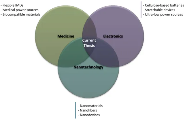
illus-tration and (b) Validation of the concept in sweated skin . . . 30 2.10 Illustration of the synergy between the three relevant scientific fields
influ-encing the current dissertation . . . 32
3.4 Photograph of the ES experimental setup used in this work . . . 43 3.5 Photograph of the mechanical testing system . . . 44 3.6 Electrochemical cell used for the CV measurements . . . 45 3.7 SEM images of electrospun membranes produced at 20 kV, 15 cm and 0.2
ml.h-1 a) CA 5% wt, b) CA 8% wt, c) CA 10% wt, d) CA 12% wt and e)
CA 14% wt . . . 49 3.8 Exponential dependence of the average fiber diameter (Daverage) with the
polymer concentration . . . 50 3.9 Fiber diameter distribution of CA solutions: (a) 10% wt (Sample No. 35),
(b) 12% wt (Sample No. 47) and (c) 14% wt (Sample No. 59) . . . 51 3.10 Dependence of the average fiber diameter (Daverage) with (a) the applied
voltage (15 and 20 kV) and the distance between the needle and the col-lector (10 and 15 cm); and (b) with the flow rate of the polymer solution through the syringe (0.1, 0.2 and 0.4 ml.h-1) . . . 52
3.11 Typical stress-strain curve obtained for the nonwoven CA membrane in uniaxial strain . . . 53 3.12 Cyclic voltammogram of an CA electrospun membrane in a dry form and
after distilled water addition . . . 55 3.13 Cyclic voltammogram of an CA electrospun membrane after SBF and NaCl
addition . . . 56 3.14 Structure of the repeating unit of a CA molecule with 33% of acetil groups 56 3.15 Cyclic voltammogram of CA electrospun membranes with different
thick-nesses after NaCl addition . . . 57 3.16 Linear dependence of the current densities with the membrane thickness . 58 3.17 Cyclic voltammogram of a CA nonporous film, with a thickness of 75 µm,
in a dry form, after NaCl addition, and after a swelling period of 24h in the same saline solution . . . 59 3.18 Electrochemical behavior of gold electrodes immersed in two different NaCl
solutions (0.9% and 5% wt/v) . . . 59 3.19 Cyclic voltammogram of a CA electrospun membrane during 9 consecutive
cycles in the presence of NaCl solution . . . 60 3.20 Cyclic voltammogram of a CA electrospun membrane during 15 consecutive
cycles in the presence of NaHCO3 solution . . . 61
3.21 PCL and EC molecular structures . . . 62 3.22 Cyclic voltammogram of PCL, CA and EC electrospun membranes in the
ization of PPy . . . 72 4.3 Illustration of the setup carried out for preparation of electrospun fibers
for electrical characterization . . . 76 4.4 Photograph of the CA membrane and the CA/PPy composite membrane
in the culture medium . . . 77 4.5 Illustration of the three structures used for battery testing: (a) PPy/cellulose
acetate membrane/PANI, (b) PPy/cellulose acetate/Au mesh and (c) PANI/cellulose acetate/Au mesh . . . 78 4.6 Photograph of the electrochemical cell setup used for battery testing (a)
general view, (b) bio-battery assembly with two carbon mesh contacts and (c) top view of the cell during electrochemical measurements with NaCl solution in the reservoir . . . 79 4.7 Conductive fabric composed of gold-based fibers used as counter electrode
for bio-battery testing (a) photograph and (b) SEM image . . . 79 4.8 Illustration of the fiber template methodology for the preparation of
com-posite fibers of CA and PPy by in situ vapor-phase polimerization . . . 81 4.9 SEM images of CA electrospun fibers: (a) uncoated, (b) coated with PPy
after 60 min and (c) 30 min of polymerization . . . 82 4.10 Photograph of CA/PPy composite membrane prepared byin situ chemical
oxidation . . . 84 4.11 Influence of oxidant/monomer ratios on electrical conductivity of CA/PPy
fibers prepared by in situ chemical oxidation . . . 85 4.12 Influence of the monomer concentration and the reaction time on the
elec-trical conductivity of CA/PPy nanofibers prepared by in situ chemical oxidation . . . 86 4.13 SEM images of the CA/PPy fibers prepared by in situ chemical oxidation
using (a) 0.025 mol.L-1, (b) 0.05 mol.L-1 and (c) 0.075 mol.L-1 of pyrrole
and a time reaction of 45 min . . . 87 4.14 SEM images of the CA/PPy fibers prepared by in situ chemical oxidation
using a pyrrole concentration of 0.05 mol.L-1 and a time reaction of 24 hours 88
4.15 Influence of monomer concentration and time reaction on the diameter of CA/PPy nanofibers prepared by in situ chemical oxidation . . . 88 4.16 TEM images of CA/PPy composite fibers prepared by in situ chemical
oxidation using 0.05 mol.L-1of pyrrole concentration and 30 min of reaction
4.20 Illustration of the fiber template methodology for the preparation of com-posite fibers of CA and PANI by in situ vapor-phase polymerization . . . . 94 4.21 Influence of polymerization time on the electrical conductivity of CA/PANI
composite fibers using an aniline concentration of 4mol.L-1 and Ox/Mon
molar ratios of 0.125, 0.25 and 0.5, respectively . . . 95 4.22 SEM images of CA/PANI composite fibers obtained after (a) 30 min, (b)
45 min and (c) 60 min of polymerization. A monomer concentration of 4mol.L-1 and an Ox/Mon molar ratio of 0.5 have been considered for all
synthesis . . . 96 4.23 Influence of polymerization time on the electrical conductivity of CA/PANI
composite fibers using an aniline concentration of 2 mol.L-1 and Ox/Mon
molar ratios of 0.25 and 0.5, respectively . . . 97 4.24 SEM images of CA/PANI composite fibers obtained after (a) 45 min and
(b) 60 min of polymerization. A monomer concentration of 2 mol.L-1 and
an Ox/Mon molar ratio of 0.5 have been considered for all synthesis . . . . 98 4.25 Influence of monomer concentration and time reaction on the diameter of
the CA/PANI fibers prepared by in situ chemical oxidation . . . 99 4.26 Photograph of CA/PANI composite membrane prepared byin situ
chemi-cal oxidation . . . 99 4.27 Typical stress-strain curve obtained for the CA/PANI composite membrane 100 4.28 Cyclic voltammograms obtained for the PPy/CA/PANI structure during
10 consecutive cycles in the presence of NaCl solution . . . 102 4.29 Cyclic voltammograms obtained for PPy/CA/Au mesh structure during 10
consecutive cycles in the presence of NaCl solution . . . 102 4.30 Cyclic voltammograms obtained for PANI/CA/Au mesh bio-battery
struc-ture during 10 consecutive cycles in the presence of NaCl solution . . . 103
5.1 Optical microscopy fluorescence images of F8T2 fibers excited with UV, blue and green light . . . 108 5.2 Optical microscopic images of CA/Au NPs composites under different light
excitation . . . 114 5.3 SEM image of CA/Au NPs composites . . . 114 5.4 (a) TEM image and (b) diameter distribution of the synthesized Ag NPs . 115 5.5 Absorption spectra of Ag NPs colloidal solution using PVP as stabilizer
and (c) TEM image of a fiber . . . 117 5.7 Microscopy images of a PVP electrospun membrane, with and without
Ag-NPs, under white light, UV, blue and green excitations . . . 118 5.8 PL spectra of a PVP electrospun membrane, with and without Ag NPs (a)
with excitation at 325nm and b) the time dependence of the laser incidence for wavelengths of 325 and 532nm . . . 119 5.9 Photographs of the antibacterial assays incubated E.coli with (a) control,
(b) PVP electrospun fibers and (c) PVP-Ag electrospun fibers; and in-cubated B. subtilis with (d) control, (e) PVP electrospun fibers and (f) PVP-Ag electrospun fibers . . . 121
6.1 Ibuprofen release profile from CA/PPy electrospun membrane with and without electrical stimulation . . . 131
A.1 Evaluation of CA electrospun SAMPLE No. 22 (a) SEM image and (b) histogram . . . 155 A.2 Evaluation of CA electrospun SAMPLE No. 23 (a) SEM image and (b)
histogram . . . 156 A.3 Evaluation of CA electrospun SAMPLE No. 24 (a) SEM image and (b)
histogram . . . 157 A.4 Evaluation of CA electrospun SAMPLE No. 34 (a) SEM image and (b)
histogram . . . 158 A.5 Evaluation of CA electrospun SAMPLE No. 35 (a) SEM image and (b)
histogram . . . 159 A.6 Evaluation of CA electrospun SAMPLE No. 36 (a) SEM image and (b)
histogram . . . 160 A.7 Evaluation of CA electrospun SAMPLE No. 37 (a) SEM image and (b)
histogram . . . 161 A.8 Evaluation of CA electrospun SAMPLE No. 38 (a) SEM image and (b)
histogram . . . 162 A.9 Evaluation of CA electrospun SAMPLE No. 39 (a) SEM image and (b)
histogram . . . 163 A.10 Evaluation of CA electrospun SAMPLE No. 40 (a) SEM image and (b)
histogram . . . 164 A.11 Evaluation of CA electrospun SAMPLE No. 41 (a) SEM image and (b)
histogram . . . 165 A.12 Evaluation of CA electrospun SAMPLE No. 42 (a) SEM image and (b)
A.14 Evaluation of CA electrospun SAMPLE No. 44 (a) SEM image and (b) histogram . . . 168 A.15 Evaluation of CA electrospun SAMPLE No. 45 (a) SEM image and (b)
histogram . . . 169 A.16 Evaluation of CA electrospun SAMPLE No. 46 (a) SEM image and (b)
histogram . . . 170 A.17 Evaluation of CA electrospun SAMPLE No. 47 (a) SEM image and (b)
histogram . . . 171 A.18 Evaluation of CA electrospun SAMPLE No. 48 (a) SEM image and (b)
histogram . . . 172 A.19 Evaluation of CA electrospun SAMPLE No. 58 (a) SEM image and (b)
histogram . . . 173 A.20 Evaluation of CA electrospun SAMPLE No. 59 (a) SEM image and (b)
histogram . . . 174 A.21 Evaluation of CA electrospun SAMPLE No. 60 (a) SEM image and (b)
1.1 Power requirements of common implantable medical devices . . . 4
3.1 Combination of the parameters studied for the ES process . . . 41 3.2 Ionic content of the human blood plasma, human sweat, simulated body
fluid solution and NaCl solution used in this work . . . 46 3.3 Summary of the morphology of the produced samples with the indication
of their fiber average diameter . . . 48 3.4 Comparison of the mechanical properties of the CA nonwoven membrane
with those of human skin . . . 54
4.1 Summary of the conditions used for in situ vapor-phase polymerization of PPy . . . 72 4.2 Monomer/oxidant mass ratios in Py polymerization by chemical oxidation 73 4.3 Evaluation of the monomer concentration and reaction time in PPy
poly-merization by chemical oxidation . . . 73 4.4 Summary of the conditions used for PANI polymerization . . . 75 4.5 Summary of the electrical conductivity and morphology of uncoated CA
electrospun fibers and CA/PPy composites . . . 83 4.6 Activation energy for PPy/ethylene-vinylalcohol copolymer composite films
as a function of PPy concentration . . . 91 4.7 Comparison of the mechanical properties of CA/PPy composite membranes
with those obtained of pristine CA nonwoven membranes . . . 92 4.8 Comparison of the mechanical properties of CA/PPy composite membranes
with those obtained from pristine CA nonwoven membranes . . . 100 4.9 Power values and main characteristics of bio-batteries evaluated . . . 104
5.1 Conductivity achieved for the electrospun membranes under no light exci-tation and UV exciexci-tation . . . 120
6.1 Summary of the main characteristics of PPy and PANI-based composites found in literature and comparison with the ones developed during this thesis126 6.2 Summary of the main characteristics of the ultra-low power sources found
B.1 Electrical conductivities of CA/PPy fibers prepared by in situ chemical oxidation using different oxidant/monomer ratios . . . 177 B.2 Electrical conductivity of CA/PPy nanofibers prepared byin situ chemical
oxidation using different monomer concentrations and reaction times . . . . 178 B.3 The influence of monomer concentration, Oxi/Mon molar ratio and reaction
AFM Atomic Force Microscope
An Aniline
BET Brunauer Emmett-Teller
BMSCs Bone Marrow Stromal Cells
CA Cellulose Acetate
CE Counter Electrode
Cipro Ciprofloxacin Hydrochloride
CNTs Carbon Nanotubes
CV Cyclic Voltammetry
Dex Dexamethasone
DMAc Dimethylacetamide
DS Dextran Sulfate
ECPs Electrically Conductive Polymers
ECM Extracellular Membrane
EC Ethyl cellulose
EGF Epidermal Growth Factor
ES Electrospinning
FITC-dextranFuorescein Isothiocyanate-dextran
FTIR Fourier Transform Infrared Mpectroscopy
F8T2 Poly[(9,9-dioctylfluorenyl-2,7-diyl)-co-bithiophene
GOx Glucose Oxidase
HA Hydroxyapatite
HPC Hydroxypropylcellulose
ILs Ionic Liquids
IMDs Implantable Medical Devices
LASER Light Amplification by the Stimulated Emission of Radiation
MEH Mechanical Energy Harvester
MEMS Microelectromechanical Systems
Mon Monomers
MTJ Musclestendon Junction
PANI Polyaniline
PC12 Pheochromocytoma 12
PCL Polycaprolactone
PDGF Platelet-Derived Growth Factor-bb
PEDOT:PSS Poly(3,4-ethylenedioxythiophene):Poly(styrenesulfonate)
PEG Poly(ethylene glycol)
PEI Poly(ethyleneimine)
PELCL Poly(ethyleneglycol)-b-poly(L-lactide-co-caprolactone
PELGA Poly(ethylene glycol)-b-poly(L-lactide-coglycolide)
PL Photoluminescence
PLA Polylactic acid
PLGA Poly(lactic-co-glycolic acid)
PLLA Poly-L-lactide
PMMA Poly(methyl methacrylate)
PPy Polypyrrole
PPVs Poly(p-phenylene vinylenes
PThs Polythiophenes
PVK Poly(9-vinylcarbazole)
PVP Polyvinylpyrrolidone
Py Pyrrole
PZT Piezoelectric lead Zirconate Titanate
P3HT Poly(3-hexylthiophene-2,5-diyl)
Ox Oxidant
RE Reference Electrode
RGG Rhodamine 6G
rhEGF recombinant human Epidermal Growth Factor
RTIL Room Temperature Ionic Liquid
SBF Simulated body fluid
SEM Scanning Electron Microscope
SEM-FIB Focused Ion Beam Scanning Electron Microscope
SDF-1 Stromal Cell Derived Factor-1
SWG Single Wire Generator
TEG Thermoelectrics Generators
TEM Transmission Electron Microscopy
THF Tetrahydrofuran
TS Tensile Strength
VEGFs Vascular Endothelial Growth Factors
VSMCs Vascular Smooth Muscle Cells
A Area
Daverage Average Diameter
E Young Modulus
Ea Activation Energy
I Current
Isc Short-Circuit Current
kB Boltzmann Constant
L Length
T Temperature
tpol Time of Ppolimerization
V Voltage
V oc Open-circuit Voltage
Wt Weight
Motivation
This chapter introduces implantable medical devices and the growing need for the
deve-lopment of flexible power sources that can supply them. Market data is presented which
supports the claim that such power sources are in increasing demand both from an
indus-trial and scientific point of views. This thesis’s objectives are subsequently presented as a
result of the innovative insight forecasted for the development of functionalized materials
that can lead to the creation of such electrical power sources. The chapter ends with an
outline of the thesis.
1.1
Introduction
Among the many diseases that may seriously impair health, some of them can only be
treated by means of medications or self-recovery mechanisms of the human body. For
that reason, there is a growing number of medical devices being implanted in patients
to treat diseases such as Parkinson’s disease, arrhythmia, diabetes, among others. Such
products are generally called Implantable Medical Devices (IMDs).
Demographic factors such as changes in standard of living, the pronounced incidence of
chronic degenerative diseases and the population aging are the foremost factors that
in-fluence the rising development of IMDs. Figure 1.1 shows the IMDs demand growth in
the United States (US). According to this estimation, orthopedic implants remains the
3317 M$
5304 M$
8100 M$
14550 M$
11338 M$
8259 M$
29400 M$
19319 M$
11901 M$ 52050 M$
35961 M$
2010 2015
Implantable medical devices Orthopedic implants
Cardiovascular implants Other
2005 23476 M$
Figure 1.1: Implantable medical devices demand growth in United States (market value in million dollars, M$), forecasted by The Freedonia Group Inc in 2010. Adapted from [1].
musculoskeletal disorders and lifestyle changes that place people at risk during sports and
often result in injuries. Hypertension is highly prevalent in the US and when uncontrolled
it may result in the occurrence of complications such as a stroke, heart failure and others.
For that reason, cardiovascular implants are expected to expand its market value and they
have the potential to reduce the overall treatment cost for heart disease and contribute
significantly to improved quality of life.
With the increasing number of people using IMDs, the mismatch between the patients’
longevity and service life of IMDs come into focus, especially in the devices which need
batteries to provide power. The IMDs that need electrical power are designated as active
devices while those that do not need are denominated as passive ones.
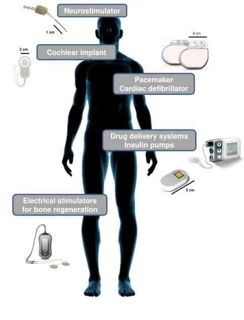
As illustrated in Figure 1.2, there are numerous active devices implanted in patients
co-vering various assistances through the whole human body. Some of them work in the
inner body to help or replace the function of certain organs.
Long-term powering and recharging of an IMD in a highly safe and efficient way is,
1 cm
Neurostimulator
4 cm
Pacemaker Cardiac defibrillator
Electrical stimulators for bone regeneration
Drug delivery systems Insulin pumps Cochlear implant
2 cm
5 cm
Figure 1.2: An overview of the most common active IMDs that can be found in the human body.
cells and bio-fuel cells have been used to power IMDs. Even if some medical batteries
may have long lifetime, the battery will eventually require replacement or recharging. For
short term applications, the conventional battery may thus provide a sufficient device
lifespan but, for long term applications, alternative power sources may be preferable to
replace these batteries, especially if the substitution or recharge procedure is invasive.
For instance, implanted biomedical devices such as cardiac pacemakers and insulin pumps
have a limited life, ranging from less than a year to perhaps 10 years. Currently,
repla-cing the battery requires its surgical removal, typically along with the entire device that it
it is also remarkable the growing number of new devices that intends to be implanted in
highly restricted spaces in the human body such as artificial retinas and cochlea. Due to
space restrictions, the power sources for such devices must be highly compact and easy
to adapt to the human body’s curvilinear surfaces. Considering the replacement cost and
risk inherent to conventional implanted batteries along with the growing need for power
sources miniaturization, it is therefore essential to develop new concepts of electrical power
sources for implantable medical batteries.
1.2
Background
Biomedical technology usually requires portable and wearable implantable devices that
can interface with biological systems. Their continued scaling and integration have
en-abled dramatic reductions in energy consumption. Table 1.1 summarizes the power
re-quirements of the most common implantable medical devices. Implanted devices such as
pacemakers, hearing aids or cochlear processors are relatively mature applications with
power consumption levels ranging from a few microwatts to a few milliwatts.
Neverthe-less, their batteries’ lifetime is limited and the replacement of the entire IMD and/or only
its battery is required, often risking the health and well-being of the patient.
Table 1.1: Power requirements of common implantable medical devices. Adapted from [2].
Device Power Battery
lifetime
Ref
Pacemaker and cardioverter-defibrillator < 10µW 10 years [3]
Hearing aid 100-2000 µW 1 week [4], [5]
Analog cochlear 200 µW 1 week [6], [7]
Neural recording 1-10 mW n.a. [8], [9]
Retinal stimulator 250 µW n.a. [10], [11]
The history of the implantable cardiac pacemaker is traced back to its inception in 1951
and can be followed through its development and trials in 1958, to its successful
usage of implanted pacemakers has been increasing. Figure 1.3 shows the evolution of
pacemaker size and weight from 1960 to 2013. As observed, there is a demand to make
these medical devices smaller, lighter and more reliable.
Currently, there has been a strong interest in ultrathin and stretchable energy devices to
meet the various design requirements of modern electronic devices. Figure 1.4 shows the
great increase of papers related to bio-batteries for medical applications and reveals the
tremendous interest for this field of research. Additionally, it is also remarkable the recent
interest for stretchable and bendable batteries as a result of the rapid growth of flexible
electronics.
In this context, this work aims to fulfill the needs previously described as well as to
con-tribute for the development of flexible electronics for medical devices. Considering the
evolution of IMDs, the development of an inexpensive and flexible energy supply system
is proposed to overcome some of the drawbacks of the existing batteries.
1960
1986
2008
2013
?
Weight : 73 g Size: 35 cm3
Weight : 55 g Size: 25 cm3
Weight : 23 g Size: 13 cm3
Weight : 2 g Size: 1 cm3
1 9 9 5 1 9 9 6 1 9 9 7 1 9 9 8 1 9 9 9 2 0 0 0 2 0 0 1 2 0 0 2 2 0 0 3 2 0 0 4 2 0 0 5 2 0 0 6 2 0 0 7 2 0 0 8 2 0 0 9 2 0 1 0 2 0 1 1 2 0 1 2 2 0 1 3 0 50 100 150 200 250 N u m b e r o f a rt ic le s
Medical or implantable batteries Flexible or stretchable batteries
Figure 1.4: Number of scientific articles using the keywords “Medical or implantable batteries” and “Flexible or stretchable batteries” published on the ISI Web of Knowledge.
1.3
Innovative insight
The scientific research presented in this thesis foresees the use of electrospun fibers in
the development of functionalized materials opening a new path for the creation of novel,
lightweight and flexible nanostructures. Polymer-based electronics represents a different
and even more challenging technology, with unique properties and with the ability to be
flexible and conform to complex surfaces. The bio-battery – or biocompatible battery –
here proposed is mainly composed of an ultrathin electrospun polymeric membrane. The
polymeric matrix is simultaneously a separator membrane and the support for the
elec-trodes. The electrodes can be formed directly on the electrospun fibers by functionalizing
them in order to achieve the desirable electrical conductivity.
Considering that harvesting energy directly from the environment is probably the most
effective and promising approach for powering long-term biomedical devices, the
bio-batteries can take advantage of the ionic content present in physiological fluids – such
be able to power a variety of ultralow-power consumption biomedical devices, such as
pacemakers, artificial retinas, insulin pumps, cochlear implants, vagus nerve stimulators,
and other future devices that will monitor bodily functions.
1.4
Objectives
Based on this innovative insight, the main objective of the current work is to develop,
produce and validate the bio-battery concept proposed. Figure 1.5 summarizes that this
bio-battery concept relies on the production of a ultrathin cellulose-based electrospun
membrane with electrical properties enhanced through fiber functionalization which is
capable of harvesting energy directly from the environment to generate the electrical
power that biomedical devices require in the long term.
Cellulose-based bio-battery activated by body fluids
Cellulose-based electrospun fibers Fibers functionalization
Applications
Supplying small medical implants
Supplying biosensors for healthcare applications
Figure 1.5: Illustration of the bio-battery concept proposed in this thesis.
The major advantage of the bio-battery concept shown in Figure 1.5 relatively to the
state-of-the-art is the flexibility associated to low quantity of material needed and thus low
production cost. Previous research and initial demonstrators showed that the bio-battery
concept here proposed, when in contact with sweated skin, could reach potentials in the
range of 0.3 V and currents around 100 µA [15]. This thesis envisions that, when fully
optimized, these bio-batteries are able to supply a variety of ultralow-power consumption
biomedical devices. To reach the scientific and technical know-how needed to provide
1. Production and characterization of cellulose-based electrospun membranes. The first task involves the study and optimization of the electrospinning process and
the morphological characterization of the membranes produced.
2. Development of functional fibers. The second task involves the use of conduc-tive polymers to enhance the electrical properties of the electrospun fibers.
3. Bio-batteries electrochemical characterization and concept validation. The final task consists in the construction of bio-batteries and the investigation of its
electrochemical behaviour and biocompatibility.
1.5
Thesis outline
The following section is an outline of the remaining chapters of this thesis:
Chapter 1: Motivation. This chapter presents the objectives and motivation of this PhD thesis.
Chapter 2: Literature review. A literature review about the power sources found in modern electronics is given, highlighting the ultralow-power sources in the medical
field.
Chapter 3: Production and characterization of cellulose-based electrospun fibers.
This chapter gives a brief overview about cellulose-based materials and describes the
production of nanofibers through the electrospinning technique. The experimental
details and the results achieved during this work are presented and discussed.
Chapter 4: Development of cellulose-based conductive fibers for bio-batteries.
The advantages of using electrically conductive polymer-based materials in
medi-cal applications are summarized in this chapter. A detailed methodology to obtain
electrically conductive composite fibers is given and the main results are presented
and discussed. Different bio-batteries structures are evaluated and electrochemically
Chapter 5: Exploring functional electrospun fibers for other applications. This chapter explores the functionalization of electrospun fibers envisaging applications
in organic optoelectronics. Preliminary results are presented and discussed.
Literature review
This chapter provides the fundamental scientific background regarding the use of nanofibers
in medicine with particular emphasis in tissue regeneration, drug delivery and biosensors.
A brief overview about the most innovative and challenging work performed in the field
of energy harvesting system envisaging medical purposes is also provided.
2.1
Electrospun fibers in medicine
Advances in nanotechnology have given the possibility of tailoring the materials’ structure
at the nanometer scale. Nanofibers are nanostructures that have at least one dimension
in the nanometer scale. Being a two-dimensional nanomaterial, nanofibers normally have
their diameters between tens and hundreds of nanometers. Due to that their low diameter
size and high specific surface area are attractive physical characteristics for a wide range
of applications. It also exhibit new or enhanced size-dependent properties when compared
with larger structures of the same material.
Several methods such as drawing, phase-separation, template, self-assembly and
electro-spinning have been used to fabricate nanofibers. The drawing process makes a single
fiber at each time using a sharp tip. For instance, the tip of an atomic force microscope
(AFM) can be used to pull a fiber from a droplet of a viscoelastic solution by applying a
voltage [16]. This process is possible only with viscoelastic materials that undergo strong
drawing.
The phase separation method consists in mixing the polymer and the solvent before
gelation. After phase separation, the solvent is removed by drying and then a porous
nanofibrous structure is created [17]. However, the whole process takes relatively long
time. For the template synthesis, a nanoporous membrane is used as a template to make
nanofibers with controlled shape and diameter [18]. This method allows the use of
elec-trically conductive polymers, metals, carbon-based materials and semiconductors as raw
materials.
An additional process is the self-assembly in which individual pre-existing components
organize themselves into desired patterns and functions [19]. The intermolecular forces
are the main mechanism responsible for the assembling of molecule units that determine
the shape of nanofibers. Similarly to the phase separation process, self-assembly is a
time-consuming process for the production of continuous polymer nanofibers. The usefulness
of these methods is thus restricted by limited number of material combinations, high costs
and low production rates. In contrast, electrospinning is perhaps the simplest process for
producing nanofibers with relatively high productivity. Electrospinning is a broadly used
technology that uses an electrical field to create a charged jet of a polymer solution [20].
In a conventional setup, a polymer solution passes through a capillary and a high voltage
is applied such that the particles within the solution are charged creating a repulsive force.
At a critical voltage, the repulsive force overcomes the surface tension of the solution and
a jet erupts from the tip of the capillary towards a grounded collector. There are a wide
range of polymers and precursors that can be electrospun such as polylactic acid (PLA)
[21], polyurethanes [22], silk fibroin [23], collagen [24], cellulose and its derivatives [25],
[26], composites [27], and ceramics [28]. The electrospinning is therefore a versatile and
inexpensive way to produce nanofibers with controllable sizes and properties.
The electrospinning also enables the production highly porous 3D structures having large
surface to volume ratios with suitable physical and chemical properties for a wide variety
of applications, such as sensors [29], antibacterial surfaces [30], scaffolds [31],
Electrospun fibers Medicine Tissue Engineering Filtration Energy & Electronics Sensors Protective Clothing
•Drug delivery •Wound dressing •Haemostatic devices
•Blood vessels & nerves regeneration •3D scaffold for tissue regeneration
•Liquid filtration •Gas filtration •Molecule filtration
•Photovoltaic, battery •LCD devices •Thermal sensor
•Piezoelectric sensor •Fluorescence optical sensor •Anti-biochemical gases •Trapping aerosols
Figure 2.1: Field of application of the electrospun fibers [34].
possible to combine different materials with singular morphological structures making it
a powerful tool to design functional materials especially for biomedical applications, such
as in tissue engineering, drug delivery and biosensors.
2.1.1
Tissues Engineering
Tissue engineering has emerged as an interdisciplinary field that applies the engineering
and life science principles to develop biological substitutes for restoring, maintaining or
improving the function of human tissues. One of the main challenges in this field is the
design and engineering of scaffolds or polymeric matrices that mimic the structure and
biological functions of the extracellular membrane (ECM).
A functional scaffold must combine a high degree of porosity and an appropriate pore size
distribution and interconnectivity with the structural integrity preventing the collapse of
scaffolds pores during neo-tissue formation. Furthermore, the scaffold should be nontoxic,
biocompatible and interact with the cells to promote adhesion, proliferation, migration
and differentiated cell functions. Many studies can be found in literature where scaffolds
bones and muscles.
• Blood Vessels
Tissue engineering of blood vessels is mostly focused on the development of vascular
grafts with small diameter (inner diameter<5 mm). The long-term unblocking of
small-diameter vascular grafts is still a challenging issue because of easy restenosis caused by
thrombosis and bursting pressure. For that reason, tissue engineering offers an
alterna-tive approach to address the need for small-diameter vascular grafts through the design
of non-thrombogenic interface.
Electrospinning provides the construction of vascular scaffolds due to the simplicity of
shaping tubular constructs using rotation and translational motion. Vaz [27] and
col-leagues have been using a sequential multi-layering electrospinning with a rotating
mandrel-type collector to produce scaffolds that mimic morphologically and mechanically the
ar-chitecture of a blood vessel (Figure 2.2). It is well known that in the media layer of the
native blood vessels, the smooth muscle cells (SMCs) and collagen fibrils have a marked
circumferential orientation to provide the mechanical strength necessary to withstand high
circulatory pressures. Additionally, the intima layer of the native blood vessels consists in
endothelial cells coating the vessels’ internal surface. Between those two layers exists an
internal elastic lamina mainly composed of elastin, which confers elastic properties to the
blood vessels. Therefore, a bi-layered tubular scaffold composed by oriented and stiff PLA
fibers in the outside and random and elastic polycaprolactone (PCL) fibers in the inside
was proposed [27]. The fabricated scaffold showed a desirable level of malleability (elastic
up to 10% strain) and proved to be capable of promoting cell growth and proliferation
making it suitable for blood vessel tissue engineering.
The electrospinning of collagen and elastin has also become possible [36]. These two
biopolymers are the main structural components of the vascular ECM. Collagen is
re-sponsible for the structural integrity and tensile strength of tissues and elastin gives them
elasticity. Electrospinning of pure collagen or elastin has shown some limitations due to
the poor mechanical properties of the produced fibers. Incorporation of biodegradable
si-Figure 2.2: Representative illustration of the arterial wall composed by intima, media and adventitia primary layers [35].
multaneously maintain a high level of bioactivity due to the presence of the biopolymer
(collagen or elastin). Lee [37] has reported the fabrication of a composite vascular
scaf-folding system by electrospinning PCL and collagen (type I) blends. These composite
scaffolds were designed to provide sufficient biomechanical properties and configured to
accommodate vascular endothelial and smooth muscle cells to be used in vascular tissue
engineering applications. Polycaprolactone is an aliphatic polyester that degrades slowly
and possesses high tensile and elongation properties for vascular grafts. The resulting
composite scaffold showed good biocompatibility and support for cell growth and
proli-feration in vitro.
During tissue repair, growth factors induce specific biological responses including cell
pro-liferation and migration, matrix synthesis, angiogenesis and release of growth factors. For
an appropriate regeneration of small-diameter blood vessels, the proliferation of vascular
endothelial cells (VECs) is desirable on the lumen of the graft in the first 7 to 10 days,
followed by the growth of vascular smooth muscle cells (VSMCs) on the outer layer, which
makes the tissue regeneration more stable without thrombosis or burst.
Vascular endothelial growth factors (VEGFs) can stimulate endothelialization and it can
factor has high ability to stimulate VSMCs proliferation [39]. To overcome this
pro-blem, different release devices must be designed to control the rapid delivery of VEGF
and prolonged release of platelet-derived growth factor-bb (PDGF). For that purpose,
two modied coaxial electrospinning techniques were developed by Zhang [40] to
encap-sulate VEGFs and PDGF, respectively, in order to regulate proliferation of VECs and
VSMCs. The double-layered membranes were prepared via coaxial electrospinning of
chi-tosan hydrogel/poly(ethyleneglycol)-b-poly(L-lactide-co-caprolactone) (PELCL) loaded
with VEGF in the inner layer and methoxy poly(ethylene
glycol)-b-poly(L-lactide-co-glycolide) (PELGA) emulsion/PELCL loaded with PDGF in the outer layer. PELGA
was added to PELCL by emulsion/coaxial electrospinning to slow down the initial release
rate of PDGF and accelerate it in the later release period. These authors have found
that dual-release of VEGF and PDGF could effectively accelerate VEC proliferation in
the first 6 days and slowly moderate VSMC proliferation in the initial 3 days while
gen-erating rapid proliferation after day 6. In summary, dual-delivery of VEGF and PDGF
using the modified electrospun membranes may facilitate revascularization and can bring
great benefits for blood vessel regeneration.
• Bones
Electrospun nanofiber meshes have been studied intensively in bone tissue engineering
due to their ability to support cell growth and differentiation into osteogenic phenotypes.
A key cellular phenotype is the osteoblast, which is the cell type that lays down the ECM
of bone tissue and thus the target cell type for recruitment and differentiation in bone
reconstruction.
Synthetic polymers and their copolymers, natural polymers, composites of natural and
synthetic polymers, inorganic materials, such as bioactive glass and hydroxyapatite (HA),
and composites of inorganic materials with synthetic and natural polymers have been used
to produce appropriate nanofiber scaffolds for osseous tissue engineering. A scaffold that
maintains stability and promotes cell growth and proliferation but gradually degrades
along with the construction of new tissues is required. Ultimately, it should be completely
of poly-L-lactide (PLLA), PLLA/HA and PLLA/collagen/HA substrates and its
applica-bility as scaffolds for bone tissue regeneration. Poly-L-lactide is a biodegradable polymer
with controlled degradation characteristics that can be used in tissue engineering and drug
delivery therapies. Hydroxyapatite is a bioceramic frequently found in biomedical implant
applications due to its biodegradability, bioactivity and osteoconductive properties. As a
bioceramic, HA cannot be easily shaped in the bone defect sites due to its natural
rigid-ity. However, synthetic biodegradable polymers can improve significantly the mechanical
properties of HA. The in vitro assays demonstrated that when HA is introduced in the
polymer matrix (PLLA/HA scaffolds) cell proliferation is observed and enhanced
com-paring to PLLA scaffolds.
Furthermore, the presence of collagen has accelerated the cell attachment and proliferation
on PLLA/collagen/HA scaffolds. Osteoblasts were found to adhere and grow actively on
PLLA/collagen/HA nanofibers with mineral deposition 57% higher than in the PLLA/HA
nanofibers. The study concluded that the synergistic effect of the presence of an ECM
protein, collagen and HA in a biocomposite scaffold holds great potential for adhesion,
proliferation and mineralization of osteoblasts.
In order to develop a bioactive membrane for guided bone regeneration, Wei Ji [42] has
proposed the functionalization of an electrospun membrane with a chemotactic factor.
Guided bone regeneration is typically used as a strategy to heal bone defects in the
cran-iomaxillofacial region. For that purpose, the creation and preservation of an isolated space
using a membrane as a barrier to avoid the invasion of fast growing epithelial and other
soft tissues into the osseous defect is required. This allows osteogenic cell populations
originating from the parent bone to inhabit the osseous defect [43]. These membranes
need to be flexible to adapt to a bone defect, preserve the space for bone formation and to
attach to soft tissues. On the other hand, biodegradability is also a requirement since it
avoids surgery in order to remove the membrane. Among the multiple types of progenitor
cells located in the bone marrow, bone marrow stromal cells (BMSCs) are considered
the most powerful ones during bone regeneration due to its multi-lineage differentiation
mobiliza-tion control, trafficking and homing of stem/progenitor cells [45]. Thus, it is essential to
increase their local concentration at the target site to induce BMSCs recruitment.
Wei Ji [42] described the preparation of an electrospun membrane of PCL blended with
B-type gelatin functionalized with stromal cell derived factor-1 (SDF-1) by physical
adsorp-tion. Among various cytokines or chemokines, SDF-1 is particularly important in BMSCs
homing and localization within the bone marrow. These authors found that PCL/gelatin
electrospun membranes clearly acted as a SDF-1 carrier providing a diffusion-controlled
release profile. The bioactive membrane also inducedin vitroBMSCs recruitment,
demon-strating a great potential for guided bone regeneration.
• Muscles
Skeletal muscle tissue is composed of bundles of highly oriented and densely packed
mus-cle fibers each with multinumus-cleated cells derived from myoblasts. The fibers are densely
packed together in ECM to constitute an organized muscle tissue that generates
lon-gitudinal contraction. For muscle tissue reconstruction, scaffolds should allow cellular
organization mimicking native individual fiber formation with unidirectional orientation.
Electrospun scaffolds should thus have appropriate material characteristics for skeletal
muscles: biocompatibility to allow cell adhesion and growth, degradability over time and
elasticity to accommodate contractile function.
Similar to what has been done for blood vessels regeneration, Choi [46] studied the
feasibil-ity of using PCL/collagen based nanofibers as a scaffold system for implantable engineered
muscles. They investigated how the orientation of electrospun PCL/collagen nanofibers
influences morphology, adhesion, proliferation, differentiation and organization of human
skeletal muscle cells. They concluded that unidirectional oriented nanofibers can
signi-cantly induce the alignment of muscle cell and myotube formation compared to randomly
oriented nanofibers. Aligned nanofiber scaffolds may provide implantable functional
mus-cle tissues for patients with large musmus-cle defects.
It has been reported so far the development of single tissue types. However, there is an
increasing demand for complex composite tissue engineering, such as tissue interfaces,
muscles-tendon junction (MTJ) tissues. One challenge in engineering MTJs is the design of a
continuous scaffold suitable for both tissue types. Muscle-tendon junctions require a high
quality interface to allow force transfer from muscle to tendon. These authors proposed
the fabrication of a dual scaffold which exhibits local mechanical property differences
mimicking the trends seen in native MTJs. Co-electrospinning was used to create three
distinct scaffold regions: a PCL/collagen region (one end side), a PLLA/collagen region
(opposite end side) and an overlap region (center). Both polymers were blended with
collagen since it improves cell attachment. The mechanical properties of the three
re-gions were evaluated: the PLLA/collagen side of the scaffold was the stiffest one showing
the lowest strain (similar to the tendon); the PCL/collagen side was the most compliant
displaying the highest strain (analogous to the muscle); and the middle region possesses
an intermediate stiffness and strain levels (similar to the junction). The structure had
distinct mechanical properties and demonstrated to be an attractive solution for MTJ
tissue engineering.
2.1.2
Drug delivery
Controlled release is an efficient process for delivering drugs in medical therapy. In a
controlled release system, the active substance is loaded into a carrier or device and then
released at a predictable rate. Exciting developments have been recently made in this
field. Due to the high surface area to volume ratio, electrospun nanofibers provide a
useful pathway for drug delivery and the release profile can be finely controlled by
mod-ulation of nanofiber morphology, porosity and composition [49]. The simplicity of the
electrospinning process can also provide the ability to conveniently incorporate
therapeu-tic compounds into the electrospun fibers. The drug can be loaded to the electrospun
fibers by several methods such as coating, embedding, and encapsulating by coaxial and
emulsion electrospinning.
Using the coating method, drug molecules can be adsorbed or cross-linked to the surface
of electrospun fibers via a physical or chemical method. Choi [50] has reported the
surface of electrospun nanobers for in vivo wound healing treatment of diabetic ulcers.
Current treatments for diabetic foot ulcers include the administration of disinfectants
followed by application of epidermal growth factor (EGF)-containing gels around the
le-sions. This work involved the electrospinning of biocompatible nanofibers with functional
amine groups on the surface (PCL and PCL/poly(ethylene glycol, PEG, block copolymer).
Upon immersion in an aqueous solution, the exposed functional amino groups on the
sur-face of the nanofibers were chemically conjugated to rhEGF by activating the carboxylic
groups of the protein. Human primary keratinocytes were cultivated on EGF-conjugated
nanofibers in order to investigate the effect of EGF nanofibers on the differentiation of
keratinocytes. Therefore, wound healing effects of the EGF nanofibers were successfully
confirmed in diabetic animals with dorsal wounds.
Another possibility to produce drug-loaded fibers is to electrospun a polymer solution
that also contains the therapeutic compound. It is required in this process that the drug
solution and polymer solution must be either miscible liquids or that solid drug particles
can be well dispersed into the polymer solution. Peng [51] has investigated the use of
poly(ethylene glycol)/poly(D,L-Lactide copolymer electrospun fibers as a drug delivery
system. This copolymer is known to have a good biocompatibility in vivo and improved
degradation rate. Paracetamol (acetaminophen, N-(4-hydroxy-phenyl) acetamide) was
chosen as the model drug since it is widely used as analgesic and antipyretic drug. The
drug was mixed with the copolymer solution and electrospun to form the fiber mats. In
vitro matrix degradation profiles of these fibers were characterized by measuring their
weight loss, the molecular weight decrease and their morphology change. It was observed
from these studies that scaffolds with smaller fiber diameter have a higher contact area
between polymer and water which, consequently, accelerates the matrix breakdown. In
addition, in vitro drug release assays have demonstrated that the release behavior mainly
depends on polymer matrix degradation and drug diffusion. In conclusion, the drug
re-lease rate can be controlled by polymer degradation which can be tuned by adjusting the
electrospun fiber diameter and its porosity.
a challenge, the electrospun of core-shell and hollow structured fibers come as a solution
for the preparation of drug delivery systems for larger molecules.
The emulsion electrospinning is an attractive approach to encapsulate a drug into a
fiber. This process is quite similar to conventional electrospinning except that the
so-lution is replaced with a water-in-oil emulsion [52]. Kai Wei [53] proposed a
fluores-cein isothiocyanate-dextran (FITC-dextran)/poly(lactic-co-glycolic acid) (PLGA) fibrous
composite scaffold. Used as a model drug, FITC-dextran was previously dissolved in an
aqueous solution and then was emulsified with the PLGA oil phase to prepare the
emul-sion to be electrospun. Morphological characterization showed that the inner component
FITC-dextran was properly wrapped in the center of PLGA. Moreover, the core-shell
structure helped the sustained release of the model drug from the fiber. A burst release
profile of 60% was obtained for the first 2 weeks after which the scaffold exhibited a
sus-tained release profile of approximately 1% cumulative release per day for 4 weeks long.
The developed scaffold exhibited a release profile that might be useful for site-specific
drug-release systems.
2.1.3
Biosensors
The integration of biomolecules with electronic elements to form multifunctional devices
has been recently the subject of intense scientific research. The need of new sensors
ex-hibiting a high selectivity and a total reliability in connection with smart systems and
actuators for real time diagnostic and monitoring of diseases has driven wonderful
devel-opments in sensors and particularly in biosensors. Biosensors can be regarded as
com-plementary tools to classical analytical methods due to their inherent simplicity, relative
low cost, rapid response and proneness to miniaturization, thereby allowing continuous
monitoring. They can integrate portable and implantable devices and be used in
biolog-ical and biomedbiolog-ical systems. However, the development of biocompatible, nontoxic and
lightweight power sources devices is still challenging. It would enable the production of
various functional devices mechanically flexible and self-sustained, allowing their
![Table 1.1: Power requirements of common implantable medical devices. Adapted from [2].](https://thumb-eu.123doks.com/thumbv2/123dok_br/16694910.743782/40.892.98.807.803.1026/table-power-requirements-common-implantable-medical-devices-adapted.webp)

![Figure 2.2: Representative illustration of the arterial wall composed by intima, media and adventitia primary layers [35].](https://thumb-eu.123doks.com/thumbv2/123dok_br/16694910.743782/51.892.244.617.125.449/figure-representative-illustration-arterial-composed-intima-adventitia-primary.webp)

![Figure 2.4: Energy harvesting from an oscillating human index finger using a single wire generator [60].](https://thumb-eu.123doks.com/thumbv2/123dok_br/16694910.743782/61.892.211.669.129.434/figure-energy-harvesting-oscillating-human-finger-single-generator.webp)

![Figure 3.2: The most relevant cellulose derivatives and their synthesis pathways [72].](https://thumb-eu.123doks.com/thumbv2/123dok_br/16694910.743782/74.892.239.717.374.966/figure-relevant-cellulose-derivatives-synthesis-pathways.webp)

