149 REM, Int. Eng. J., Ouro Preto, 71(2), 149-157, apr. jun. | 2018
Dalilah Pires Professora
Universidade Federal de São João del-Rei – UFSJ Departamento de Tecnologia em Engenharia Civil, Computação e Humanidades
Ouro Branco - Minas Gerais - Brasil Doutoranda em Engenharia Civil
Universidade Federal de Ouro Preto - UFOP Escola de Minas
Departamento de Engenharia Civil Ouro Preto – Minas Gerais - Brasil [email protected]
Rafael Cesário Barros Doutorando em Engenharia Civil
Universidade Federal de Ouro Preto - UFOP Escola de Minas
Departamento de Engenharia Civil Ouro Preto – Minas Gerais – Brasil [email protected], [email protected]
Paulo Anderson Santana Rocha Professor
Universidade Federal de Ouro Preto - UFOP Escola de Minas
Departamento de Engenharia Civil Ouro Preto – Minas Gerais – Brasil [email protected]
Ricardo Azoubel da Mota Silveira Professor
Universidade Federal de Ouro Preto - UFOP Escola de Minas
Departamento de Engenharia Civil Ouro Preto – Minas Gerais – Brasil
[email protected], [email protected]
Thermal analysis of
steel-concrete composite
cross sections via CS-ASA/FA
Abstract
When exposed to high temperatures, such as in a fire situation, the physical and resistance characteristics of the materials employed in the structure deteriorate as the temperature increases. This fact promotes a considerable loss in the bearing capacity and stiffness of the structural system. The verification of a structure exposed to fire depends primarily and principally on the thermal analysis of the cross section of the structural element. This analysis permits determination of the temperature variation or temperature range in the element from the boundary conditions provided by the fire model adopted. As such, this study had the objective of performing a thermal analysis in a transient regime by means of a finite element method on steel-concrete composite cross sections that are employed in civil construction through use of the Computational Sys-tem for Advanced Structural Analysis/Fire Analysis (CS-ASA/FA). Two cross sections are analyzed and the results obtained were satisfactory. In addition, different iterative solution processes were adopted in the analysis. Parametric studies were also performed related to the mesh variation of the finite elements and time increase. From the results, it was possible to conclude that CS-ASA/FA can supply the necessary information when a thermo-structural analysis is performed for the evaluation of strength and stiffness losses of the structural material when exposed to fire.
Keywords: thermal analysis, fire, temperature, composite cross section, FEM. http://dx.doi.org/10.1590/0370-44672016710155
Civil Engineering
Engenharia Civil
1. Introduction
The structure integrity under a fire condition involves the knowledge of the temperature influence in the structural behavior. Such an understanding has been achieved through increasingly sophisticated numerical models. It is known that the high temperature, which is common in a fire situation, causes changes in the physical characteristics and mechanical strength
of the materials. The characteristics of both steel and concrete deteriorate during exposure to fire, and the loss of strength and stiffness increases significantly with the rising temperature. Thus, in the analysis of structures exposed to high temperatures, one important control parameter is fire exposure time. Fire resistance is defined as the ability of a material or structural
element to continue carrying out, for a certain time, the functions for which it was designed, while being exposed to the action of fire. This time is called Required Fire Resistance Time (RFRT).
standards). By means of this temperature, it is possible to obtain the temperature of the structural element to be used in the project calculations. The temperature range of the cross section of the structural element is determined through a thermal analysis. In structural problems where fire exposure is considered, the thermal analysis basically consists of two parts: (i) determining the
heat transfer by convection and radiation from the fire along the boundary of the element of interest, and (ii) determining the heat transfer by conduction in the interior of the structural elements.
Taking into consideration that the structure is exposed to fire, a consecutive resolution of the two systems of equations within each time interval can be performed.
The first equation system results from the integration of the heat conduction equation (thermal analysis) and the second system corresponds to the incremental equilibrium equations (structural analysis) according to Figure 1. Therefore, the information from the thermal analysis is essential for the correct evaluation of the structure under high temperatures.
Figure 1
Solution of the thermo-structural problem.
Herein, the computational module CS-ASA/FA (Computational System for Advanced Structural Analysis/Fire Analy-sis; Pires et al., 2015) is used to perform
a thermal analysis in transient regime of steel-concrete composite cross sections of structural elements. This module was developed based on the Finite Element Method (FEM) (Cook et al., 1989) and
is part of an ample computation system denominated CS-ASA (Computational System for Advanced Structural Analysis; Silva, 2009). Within the ASA, the CS-ASA/FA is able to perform a thermal analy-sis of the cross section in both permanent and transient regimes, as well as a thermo-structural analysis of steel structures when coupled to the module CS-ASA/FSA (Com-putational System for Advanced Structural Analysis/Fire Structural Analysis; Barros et al., 2016). Therefore, the objective of this
study was to perform a thermal analysis of the steel-concrete composite cross sections, exploring the features of CS-ASA/FA and in the future, make it possible to thermo-structurally analyze the composite struc-tures. Within the principal characteristics of the CS-ASA/FA module, the following are worth highlighting:
- its total integration with the GID graphic pre-processor elaborated by CIMNE (2004);
- the possibility of using isoparamet-ric triangular finite elements with 3 and 6 nodal points and isoparametric rectangles with 4 and 8 nodal points;
- the possibility of employing differ-ent strategies for the non-linear solution of thermal problems;
- its total integration with the CS-ASA/FSA module which already per-forms well for thermo-structural analysis
of steel structures.
It should be noted that a large part of the research in Brazil related to the analysis of structures in fire situations has been essentially numerical, with intensive developments and advances in recent years, such as the works of: Caldas (2008); Rigobello (2011); Landesmann (2012); Pierin and Silva (2014); Pierin et al. (2015); Pires et al. (2015); Barros et al.
(2016) and Barros (2016). In the interna-tional context, works by Othuman and Wang (2011), Zandi et al. (2012), Zang
and Usmani (2015), and Wong (2017) can be highlighted.
The next section details the method-ology used to obtain the equilibrium equa-tion of the heat transfer problem while also explaining the nonlinear solution, which is characterized by a simple incremental or incremental-iterative scheme solution. Temporal cycle
Δt = 1, Max N0 of increments
Fire Structural Analysis
Thermal Analysis CS-ASA/FA
Structural Analysis
Thermal cycle End?
No Yes
Results
Fire Start
151 REM, Int. Eng. J., Ouro Preto, 71(2), 149-157, apr. jun. | 2018
considering the constitutive relationship of the material (Fourier's law) and sat-isfying the boundary conditions. In (1),
kx and kyare the thermal conductivities
in the x and y directions, respectively, T
is the temperature, Q is the heat
gener-ated inside the element per unit volume and time, ρ is the unit material mass, c
is the specific heat of the material, and t is the fire exposure time.
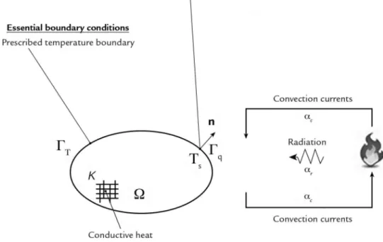
For solids, the heat transfer within the body volume (domain) oc-curs only by conduction. Being a solid body surrounded by a fluid, as shown in Figure 2, the convection and radia-tion boundary condiradia-tion can be used for the solution of the solid domain problem (radiative convective
bound-ary), besides a prescribed heat flux. Many engineering problems are governed by a valid differential equa-tion in a domain and are subject to boundary conditions on the surface. In general, however, analytical solu-tions for these differential equasolu-tions are known only for some simple cases. Nevertheless, the values of an unknown function (problem solution) for some predetermined points can be obtained through numerical methods. It is possible to obtain approximate solutions to differential equations us-ing the Weighted Residual Methods (WRM). Among these methods, Galer-kin stands out for its generalizability and accuracy of numerical results. This
approach, together with the Finite Ele-ment Method (FEM), is applicable to a wide variety of engineering problems. FEM is a widespread numerical proce-dure used in the analysis of structures and continuous media. It is based on the concept of the discretization of structure and continuous media and, from there, obtaining approximate numerical solutions. Thus, FEM at-tempts to divide a continuous medium into subdomains, such as elements, which are interconnected through nodal points where the degrees of freedom to be determined are defined. The basic idea is to transform a com-plex problem into a sum of several simple problems.
Figure 2 Boundary conditions in a solid domain problem.
Galerkin’s method is used to mini-mize the error when approaching the problem solution. From its weak
formu-lation, and in the FEM context of con-sidering the contribution of all elements of the mesh, it arrives at the equilibrium
equation governing the transient problem of heat conduction, described below in matrix form:
{ }
t
∂
⎧
⎫ +
=
⎨
⎬
∂
⎩
⎭
T
C
K T
R
(2)2. Equilibrium equation by FEM
The heat conduction problem consists of solving the following
par-tial differenpar-tial equation (Peréz, 2001; Halliday et al., 2009):
(1)
(
)
{
}
n+1 n
n+
T
T
n+T
n+11
T
n n+t
θ θθ
⎧
⎨
Δ
−
⎫
⎬
+
θ
+ − θ
=
⎩
⎭
K
R
C
(4)The equation above can be rearranged as follows:
(5)
or even more compactly as:
{ }
n 1+=
(6)with
The temperature values in the current time step, n+1, are found using the
tem-peratures calculated in the previous time step (n) and using the nodal heat flows in
the current and previous time steps. Inside each time interval, the parameter θ defines the instant at which Equations (5) or (6) are satisfied. It is possible to obtain differ-ent integration schemes in time by varying the parameter θ. Herein, θ is adopted as being equal to 0.9 in the analysis, in ac-cordance with SAFIR software (Franssen, 2005). More information about integration schemes in time and a detailed problem solution of transient heat conduction can be found in Bathe (1996), Lewis et al. (2004),
Rigobello (2011), Nunes (2014) and, more
recently, in Barros (2016).
As can be observed, Equation (6) is strongly non-linear due to its dependency on the material’s thermal properties. It is worth emphasizing that there is not a general method to resolve such a non-linear system of equations. The CS-ASA/FA module contains two implemented proce-dures that deal with the resolution of the system of equations described in (6): simple incremental and incremental-iterative. For the latter, the iterations can be performed through the use of the Picard algorithms, also known as a successive approximation method, and Newton-Raphson (Cook et al., 1989). The methodology described in
this section is detailed in Table 1, as well
as the solution algorithms available in CS-ASA/FA.
It should be noted here that, for a thermal analysis that describes the dy-namics of fire, there exist several options of models. These models are usually represented by heating curves that are standardized and provided by current standards, or by specific curves defined for cases of nonconventional heating. In prescriptive procedures for design and laboratory testing in furnaces to deter-mine the fire resistance of structural ele-ments, the gas temperature is calculated using the standard fire curve (ISO 834-1). Thus, this study adopts this heating curve, which is given by:
(7)
where θ is the temperature (°C) of the gases and t is the time in minutes of fire exposure.
The matrices N, B, and D in the
above equations are the matrix of in-terpolation functions; the matrix that contains the derivatives with respect to
x and y of the interpolation functions;
and the matrix containing the thermal conductivities, kx and ky.
For thermal analysis in module CS-ASA/FA, there are available: the two triangular elements T3 and T6, with
3 and 6 nodes, respectively; and two quadrilateral elements Q4 and Q8, with
4 and 8 nodes, respectively.
To solve Equation (2), this study
adopts a numerical integration strategy in time based on the Finite Difference Method (FDM; Bathe, 1996; Burden and Faires, 2008). Therefore, the equilibrium equation of the transient heat conduction problem (2) can be rewritten as:
{ }
nn n
n
t
+θθ
+ +θ
+θ
∂
⎧
⎫
⎨
∂
⎬
⎩
⎭
T
(3)The temperature variation tn+θ can
be written by a Taylor series expansion
and, after algebraic manipulations, the equation adopted to calculate the
tem-peratures at each time step is given by: is the thermal conductivity matrix;
is the nodal heat flux vector; and T is the nodal temperatures vector meant to be determined.
153 REM, Int. Eng. J., Ouro Preto, 71(2), 149-157, apr. jun. | 2018
Table 1
Solution algorithms: heat transfer transient problem
T n+
1b. Calculate thermal conductivity matrix:
(
)
n n t n
ˆ
+ = + + +
1e. Get: ˆ + = +
(
1)
t + +{ }
1n n n 1+ = ˆ + ˆ +
INCREMENTAL -ITERATIVE (PICARD)
1. INCREMENTAL PROCESS:inc = 1, 2,..., nmax
2. ITERATIVE PROCESS (PICARD):k = 1, 2,..., nmax
2a. Do:
R
ˆ
n+ = 1Tn+ = 2Tn+ = 0.0 2b. Calculate the capacitance matrix:T
n+ c d
C = N N
2c. Calculate thermal conductivity matrix:
n+ +
2d.Calculate the heat flux vector:
0
n+ +
(
ˆ
+ = + +
2g. Determines the 1st approximation:
1 2
n n
tolerance 1
n
+ +
+ <
T T
T
YES:
Calculate the vector
1 0 n+
T = T
-The other heating curves, although they have been implemented in the
CS-ASA/FA, are not addressed in this study. However, more information on
them can be obtained from Franssen et al.
(2009), Bailey (2011) and Barros (2016).
3. Numerical examples
This section aims to determine, by transient thermal analysis, the structural behavior of composite cross sections sub-jected to high temperatures, using the CS-ASA/FA (Pires et al., 2015). As already
mentioned, this module is part of the CS-ASA program (Silva, 2009) and was developed for the analysis of structures ex-posed to fire. Therefore, it is indispensable that the thermal analysis be performed in a correct manner so as not to compromise
the response of the thermo-structural analysis. The CS-ASA/FA module was used with success by Barros (2016) in the first step of the thermo-structural analysis of steel structures. Herein, two steel-concrete composite cross sections having different geometric and physical characteristics are analyzed to evaluate the capacity of CS-ASA/FA to supply the necessary infor-mation from the thermal analysis for the composite structures. Besides this, results
are obtained for two types of solution pro-cesses: simple incremental and incremental-iterative (Picard or Newton-Raphson). The objective is to demonstrate the influence of these processes on the response of the problem. The thermal properties of steel are those given by EN 1993-1-2: 2005 and of concrete are those given by EN 1992-1-2: 2004, considered to be varying with the temperature. The adopted parameters are highlighted in each example below.
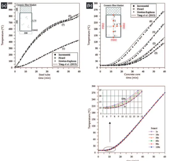
3.1 Concrete-filled steel tubular section
The first example, shown in Figure 3a, concerns a rectangular, steel concrete-filled tubular section. Yang et al. (2013) pointed
out that, in recent decades, researchers have studied in depth the behavior of this cross section’s structural elements subjected to uniform fire. Where knowledge is limited, however, is on the performance of the structural components when exposed to fire on three sides, a common real-world scenario. Hence, these authors analyzed such an example, experimentally, using a ceramic fiber blanket to simulate the side
not exposed to fire.
Figure 3 shows the temperature distribution within the cross section being studied: in (a) the points on the steel profile, and (b) the points in the concrete region. For the discretization of the cross section, the study adopted a mesh structured with 308 quadrilateral finite elements, linear. A time increment, Δt, of 10s was used. It can be seen that the obtained responses in this study show good agreement with the experimental results.
To verify the influence of the time
increment, Δt, in obtaining the
tempera-ture distribution in the section, the study adopted point 6 in the concrete region (Fig-ure 3b) and Δt was varied by the following
values: 1s, 10s, 30s, 60s, 90s, and 120s. The results are shown in Figure 4. See that with a larger increment of time, the temperature tends to be higher in the first few minutes of exposure to fire (between 5 to 20 min). A maximum difference was observed of about 4°C between curves where Δt was equal to 1s and 120s. As the fire exposure time increases, the curves practically coincide.
Figure 3
Temperature versus time curves: concrete-filled steel tubular section.
(a) (b)
Figure 4
155 REM, Int. Eng. J., Ouro Preto, 71(2), 149-157, apr. jun. | 2018
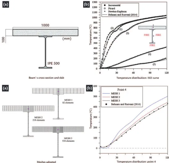
3.2 Steel-concrete composite beam section
The other section chosen to evaluate its behavior under the action of fire was the cross section of a composite beam of steel and concrete, illustrated in Figure 5a.
The composite beam was made by the IPE 500 profile. It is part of a seven-story structure studied by Behnam and Rezvani (2014). Using SAFIR software, these authors investigated the structure being subjected to the action of fire spreading (Franssen, 2005). The study also considered the uniform action of fire represented by the curve described by Equation (7). The results presented by the
authors, considering the ISO-834 curve, are used for comparison.
Figure 5b shows the temperature-versus-time curve for five points of the cross-section. It is noteworthy that for the discretization of the section this study used a mesh structured with 530 quadrilateral finite elements and 4 triangular finite ele-ments, both linear, which is shown in Figure 6a. Again, you can see there is good agreement between the results obtained in this study and those provided by Behnam and Rezvani (2014).
In obtaining the temperature
distri-bution in the section, point 4 was chosen to check the influence of discretization of the finite element mesh. The adopted meshes are illustrated in Figure 6a, where the number of finite elements used in each is highlighted. Two meshes were adopted (MESH 1 and 2) that were less refined than the mesh initially adopted for the study of the section (MESH 3). The results are shown in Figure 6b, where it can be clearly seen that the more refined the mesh produced, the better the result; that is, the values converge more with those found in literature.
(a) (b)
Figure 5 Distribution of temperature inside beam.
(a) (b)
Figure 6 Variation of the cross-section’s finite element mesh.
4. Final remarks
In numerical contexts, the analysis of structural elements at high temperatures is made possible by two fundamental phases: thermal analysis and structural analysis, which are interconnected. It is important to consider how the inelastic behavior of the material is affected by temperature as well as to consider the second-order effects that arise due to changes in geometry. After all, it is known that the structural elements bearing capacity is significantly reduced as temperatures rise. In addition to changing the characteristics of the cross
section, a temperature increase also causes the appearance of thermal strains in the stretching behavior of materials. Thus, the information from the thermal analysis is key to achieving, in a satisfactory way, the thermo-structural behavior.
This article presents the thermal analysis of cross sections of structural elements commonly used in construc-tion. The results were compared with the experimental and numerical solutions found in literature.
From the examples analyzed in the
previous section, we can conclude that the CS-ASA/FA computation module can satisfactorily simulate the effect of high temperatures on the cross sections of structural elements. These results have agreed with those found in literature. Both experimental (Yang et al., 2013)
and numerical (Behnam and Rezvani, 2014) results found in literature were used for comparison.
incremental-iterative (Picard and Newton-Raphson), as well as the length of the incremental time and the mesh of the finite elements; all of which influence temperature dis-tribution. It has also been observed that the two solution procedures are efficient in obtaining the thermal response of the two sections and almost no difference was verified in the response between them. The simple incremental procedure is more efficient regarding the processing time in function of the solution algorithm shown in Table 1, where the volume of operations needed to be performed is less. However, a deeper study involving more samples and analysis situations is necessary to define a better option for the solution in this case. Regarding the time incremental variation adopted in
this analysis, an insignificant influence was encountered, or in other words, there occurred a maximum difference of 4°C between the values of 1s and 120s. This difference between the curves (tempera-ture versus time) may be related to the standard fire curve, Equation (7), since it varies logarithmically. Adopting time in-crement values equal to 1s and 120s, the gas temperature is equal to 38.75°C and 444.50°C, respectively, at the end of the first time increment. However, there can be seen in Figure 4 a small variation of structural element temperature (cross sec-tion), about 4°C. This small influence of the time increment allows larger values to be used without compromised response, since smaller incremental values lead to a higher processing time. A greater
sensibil-ity was observed in relation to the finite element mesh discretization. Depending on the cross section, too coarse a mesh would not accurately represent the physi-cal problem (MESH 1), being necessary a certain refinement for better results, as verified in the second example presented. It is worth mentioning that more detailed studies about the finite element mesh discretization and the time increment were presented in Barros et al. (2016),
for steel cross sections, who also used the CS-ASA/FA computational module.
Finally, we can affirm the CS-ASA/ FA module is also efficient in the ther-mal analysis of steel-concrete composite cross sections, being able to supply data for a future thermo-structural analysis of composite structures exposed to fire.
Acknowledgments
The authors are grateful for the finan-cial support received by CAPES, CNPq,
FAPEMIG and UFOP. They also thank professors John White and Harriet Reis
by text review.
References
BAILEY, C. G. One Stop Shop in Structural Fire Engineering by Manchester Uni-versity. [online] Disponível: http://www.mace.manchester.ac.uk/project/research/ structures/strucfire/, 2011.
BARROS, R.C., PIRES, D., LEMES, I.J.M., ROCHA, P.A.S., SILVEIRA, R.A.M. Análise termomecânica de estruturas de aço via acoplamento MCD/MRPR. In:
Ibero-Latin American Congress on Computational Methods in Engineering, 37.
Brasília, DF, Brasil, v.2, p. 237-253, 2016.
BARROS, R.C. Avaliação numérica avançada do desempenho de estruturas de
aço sob temperaturas elevadas. Ouro Preto: Programa de Pós-Graduação em
Engenharia Civil, Deciv/EM/UFOP, 2016. (Dissertação de Mestrado). BATHE, K.J. Finite element procedures. New Jersey: Prentice-Hall, 1996. 1037 p.
BEHNAM, B., REZVANI, F. H. Structural evaluation of tall steel moment-resis-ting structures in simulated horizontally traveling postearthquake fire. Journal
of Performance of Constructed Facilities, 04014207(12), 2014.
BURDEN, R. L., FAIRES, J. D. Análise numérica (8ª ed.). CENGAGE Learning,
2008. 736 p.
CALDAS, R. B. Análise numérica de estruturas de aço, concreto e mistas em
Situa-ção de Incêndio. Belo Horizonte: Programa de Pós-Graduação em Engenharia de
Estruturas, EE/UFMG, 2008. (Tese de Doutorado).
CIMNE. GID Pré/pos Processador Gráfico – Versão 7.2. Centro Internacional de Métodos Numéricos em Engenharia. Barcelona, 2004.
COOK, R., MALKUS, D., PLESHA, M. Concepts and applications of finite element
analysis. (3rd ed.). New York: John Willey & Sons, 1989.
EN 1992-1-2. Eurocode 2 – Design of concrete structures. Part 1-2: General ru-les, structural fire designing. European Committee for Standardization – CEN, Brussels, 2004.
EN 1993-1-2. Eurocode 3 – Design of steel structures. Part 1-2: General rules, structural fire desing. European Committee for Standardization – CEN, Brussels, 2005. FRANSSEN, J. M., KODUR, V., ZAHARIA, R. Designing steel structures for fire
safety. CRC Press, 2009.
FRANSSEN, J. M. SAFIR - A thermal/structural program modelling structures under fire. Engineering Journal AISC, v.42, n.3, p. 143–158, 2005.
HALLIDAY, D., RESNICK, R., WALKER, J. Fundamentos de Física 2. (8ª ed.). São
157 REM, Int. Eng. J., Ouro Preto, 71(2), 149-157, apr. jun. | 2018
Received: 1 November 2016 - Accepted: 3 June 2017.
ISO 834-1. Fire resistance tests – Elements of buildings construction, Part 1: General requirements. ISO – International Organization for Standardization, Geneva, 1999. LANDESMANN, A. Refined plastic-hinge model for analysis of steel-concrete structu-res exposed to fire. Journal of Constructional Steel Research, 71, p. 202-209, 2012.
LEWIS, R. W., NITHIARASU, P., SEETHARAMU, K. N. Fundamentals of the finite
element method for heat and fluid flow. Chichester: John Wiley & Sons, 2004.
NUNES, N. E. M. Código computacional para análise térmica tridimensional de
Estruturas em situação de incêndio. São Carlos: Programa de Pós-Graduação em
Engenharia de Estruturas – Escola de Engenharia de São Carlos da Universidade de São Paulo, 2014. 152 f. (Dissertação de Mestrado).
OTHUMAN, M. A., WANG, Y. C. Elevated-temperature thermal properties of lightweight foamed concrete. Construction and Building Materials, 25,
p. 705–716, 2011.
PÉREZ, J. P. Thermodynamique. Fondements et applications. Paris, Masson. (3rd ed).
2001. 584 p.
PIERIN, I., SILVA, V. P., LA ROVERE, H. L. Análise térmica de estruturas bidimen-sionais em situação de incêndio. Revista IBRACON de Estruturas e Materiais, 8,
p. 25-48, 2015.
PIERIN, I., SILVA, V. P. Análise térmica de estruturas bidimensionais em situação de incêndio por meio do método dos elementos finitos. Jornadas Sul Americanas de
Engenharia Estrutural, 2014.
PIRES, D., BARROS, R.C., LEMES, I.J.M., SILVEIRA R.A.M., ROCHA, P.A.S. Aná-lise térmica de seções transversais via método dos elementos finitos. In: CILAMCE,
36. Anais... Rio de Janeiro, RJ, Brasil, v. 1, p. 1–19, 2015.
RIGOBELLO, R. Desenvolvimento e aplicação de código computacional para análise
de estruturas de aço aporticadas em situação de incêndio. São Carlos: Programa de
Pós-Graduação em Engenharia de Estruturas – Escola de Engenharia de São Carlos da Universidade de São Paulo, 2011. 272 f. (Tese de Doutorado).
SILVA, A.R.D. Sistema computacional para a análise avançada estática e dinâmica
de estruturas metálicas. Ouro Preto: Programa de Pós-graduação em Engenharia
Civil, DECIV/Escola de Minas/UFOP, 2009. 322 f. (Tese de Doutorado).
WONG, M. B. Temperature analysis of partially heated steel members in fire. Journal of
Constructional Steel Research, 128, p. 1-6, 2017.
YANG, H., LIU, F., GARDNER, L. Performance of concrete-filled RHS columns expo-sed to fire on 3 sides. Engineering Structures, 56, p. 1986-204, 2013.
ZANDI, Y., BURNAZ, O., DURMUŞ, A. Determining the temperature distributions of fire exposed reinforced concrete cross-sections with different methods. Research
Journal of Environmental and Earth Sciences, v.4, n.8, p. 782-788, 2012.