Abstract
In this paper, a geometrically nonlinear analysis of functionally graded material (FGM) shells is investigated using Abaqus software. A user defined subroutine (UMAT) is developed and implemented in Abaqus/Standard to study the FG shells in large displacements and rotations. The material properties are introduced according to the integration points in Abaqus via the UMAT subroutine. The predic-tions of static response of several non-trivial structure problems are compared to some reference solutions in order to verify the accuracy and the effectiveness of the new developed nonlinear solution proce-dures. All the results indicate very good performance in comparison with references.
Keywords
Geometric nonlinear; Functionally graded shells; Numerical imple-mentation.
Numerical Analysis of Geometrically Non-Linear
Behavior of Functionally Graded Shells
1 INTRODUCTION
Functionally Graded Materials (FGMs) are the heterogeneous composite materials in which the ma-terial properties are gradually varied along one, two or three directions as a function of the position coordinates. The most known FGMs are composed of transition alloys from metal at one surface to ceramic at the opposite surface (Yang and Shena 2003; Woo and Merguid 2001; GhannadPour and Alinia 2006). Thanks to the low thermal conductivity of ceramic (Hasselman and Youngblood 1978; Niino and Maeda 1990), this kind of FGMs was introduced as high thermal resistant materials for applications such as nuclear reactors, chemical plants, heat engine components and aerospace vehicles.
J. Mars a, * S. Koubaa a M. Wali a F. Dammak a
a Engineering Production Mechanics and
Materials Unit (UGPM2), National Engineering School of Sfax, University of Sfax, B.P. 1173-3038, Sfax, Tunisia [email protected]
[email protected] [email protected]
* Corresponding author
http://dx.doi.org/10.1590/1679-78253914
Several research works are obtainable in literature to analyze the linear mechanical behavior of FG shell structures (Tornabene 2009; Mantari and Monge 2016; Lee et al. 2009). Typically, FG shell structures were presented using: (i) Kirchhoff-Love theory, Chi and Chung (2006), where the shear strains are assumed zero, which is not acceptable for FG shell; (ii) the First-order Shear Deformation Theory (FSDT) (Praveen and Reddy 1998; Thai and Kim 2015), which gives a correct overall assess-ment. Notice that the shear correction factors should be incorporated to adjust the transverse shear stiffness; (iii) the High-order Shear Deformation Theory (HSDT) (Neves et al. 2012; Wali et al. 2014, 2015; Frikha et al. 2016) in which the equations of motion are more complicated to obtain than those of the FSDT; among other theories.
It is certainly plausible that linear finite element (FE) models cannot be able to accurately predict the structural response presenting large elastic deformations and finite rotations. Indeed, according to Yu et al. (2015), several practical problems of FG structures require a geometrically non-linear formulation, such as the post-buckling behavior of structures used in aeronautical, aerospace as well as in mechanical and civil engineering. In such cases, it becomes crucial to develop efficient and accurate nonlinear FE models.
It is well known that analytical solutions of shell problems are very limited. Hence, most of reference solutions are previously reported numerical solutions. Particularly, for FE geometric non-linear analysis of FG shells, several research papers are surveyed (Praveen and Reddy 1998; Reddy 2000; Kattimani and Ray 2015; Duc et al. 2017; Arciniega and Reddy 2007a, 2007b; Alinia and Ghannadpour 2009; Phung-Van et al. 2014; Kim et al. 2008; Hajlaoui et al. 2017; Frikha and Dammak 2017; Asemi et al. 2014 and Ansari et al. 2016). In these references, a number of theoretical formula-tion and finite element models based on von Karman, Kirchhoff-Love, FSDT and HSDT theories were proposed to study the geometrically non-linear behavior of FGMs Structures.
Hosseini Kordkheili and Naghdabadi (2007) derived a FE formulation for the geometrically non-linear thermoelastic analysis of FGM plates and shells using the updated Lagrangian approach. Later, Zhao and Liew (2009) conducted a geometrically non-linear analysis of FGM shells under mechanical and thermal loading using the element-free kp-Ritz method. The formulation was based on the mod-ified version of Sander’s non-linear shell theory, accounting for transverse shear strains, rotational inertia, and moderate rotations in the von Karman assumption. The arc-length method, combined with the modified Newton–Raphson approach, was employed to trace the full load–displacement path. Recently, Moita et al. (2016) has introduced a non-linear formulation for general FGM plate-shell type structures. The formulation relayed on geometric and material non-linear behavior. Using the Newton–Raphson incremental-iterative method, the incremental equilibrium path was obtained, and in case of snap-through occurrence the automatic arc-length method was used.
One can notice that, applied to FGM, the studies of the non-linear behavior of plates and shells were limited generally to a von-Karman assumption that only takes into account membrane forces, which is limited to moderately small deformations (Reddy 2000; Phung-Van et al. 2014).
meshed with 5 to 10 elements. The main limitation of this method is the expensive CPU time and the non-continuous segmented distribution of material properties.
In the other front of the development of numerical methods, authors used the commercial software ABAQUS for geometrically non-linear analysis of isotropic shells, Sze et al. (2004). To the best knowledge of the authors, there are no further accessible documents in literature dealing with ABAQUS implementation of geometric non-linear behavior of FGM shells. This is the main motiva-tion for the present work, which introduces an alternative method to analyze the geometric non-linear static response of FG shells. The material properties are introduced according to the integration points via the implementation of the user-material UMAT subroutine into ABAQUS software. This article introduces several trivial examples for the validation of the static response of geometrical non-linear shell elements. All the results indicate very good performance in comparison with references.
2 MATERIAL PROPERTIES
In this study, the shell structure is considered to be a mixture between metal and ceramic constituents. The material properties of the FG shell are functions of volume fractions of constituent materials. The Young’s modulusE z( ) of the functionally graded shell can be expressed as:
m
c m
cE z E E E V z (1)
where Em and Ec represent Young’s modulus of the metal and ceramic, respectively. The ceramic
volume fraction V zc
follows the four-parameters power law distribution, Tornabene (2009): / / /
1 1
: 1
2 2
n c c
a b c n
z z
FGM V z a b
h h
(2)
where the volume fraction index n
0 n
. By using Eqs.1 and 2, when n 0 ,the materiel is fully ceramic and when n, the homogeneous metal is recovered. The parameters a, b and c are the material variation profile through the FG shell thickness.3 NON-LINEAR ANALYSIS THEORY
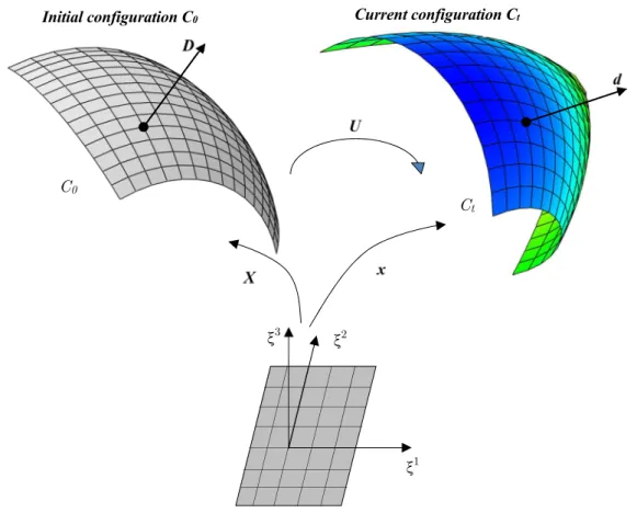
In this section, the geometry and kinematics of non-linear FSDT shell model are briefly described. The reference surface of the shell is assumed to be smooth, continuous and differentiable. Initial and current configurations of the shell, are denoted by C0 and Ct, respectively. Variables associated to
0
C (resp. Ct) are denoted by upper-case letters (resp. lower-case). Vectors will be denoted by bold letters.
3.1 Kinematic Assumptions
located at a distance z on the shell director D. The position vector of (q), in Ct and C0, are given
respectively by
1, ,2
1, 2
1, 2
q S S z p S S z S S
X X D (3)
1, ,2
1, 2
1, 2
1, 2
q S S z p S S z S S S S
x x d (4)
Where z
h/ 2, / 2h
is the thickness coordinate of the shell, d and D are the director vectors in the deformed and reference configuration respectively (Fig. 1) and is the stretching parameter. The parameter depends on the actual state of deformation gradient and calculated in the mid-surface (z=0). We assume that Xp and Xq are functions of curvilinear surface coordinates
S . In
the above,
S S1, 2
are local surface coordinates that are orthogonal, Fig. 2. Parameterizations of theshell material points are carried out in terms of curvilinear coordinates ( 1, 2, 3=z). The strain tensor can be decomposed in in-plane and transverse shear strains as
3 . e z
a d , , 1,2 (5)
where we have neglected derivatives of with respect to
S , aare the local orthonormal shell direction in deformed state and
3, e and are transverse shear strains, membrane and bendingand given by
1 2
e a A , 1
2 b B
(6)
where A and a are the components of the metric tensor in the reference and deformed configu-ration respectively,
, . ,
p p
A X X , a xp,.xp, (7)
where we use the notation
.,
. /S. B and b are the curvature tensors in the reference and deformed configuration respectively, . , , . ,
p p
B X DX D , b xp,.d,xp,.d, (8)
In matrix notation, the membrane, bending and shear strains vectors are given by
11 22 12 2 e e e
e ,
11 22 12 2
, 13
Figure 1: The initial and current configuration of shell structure
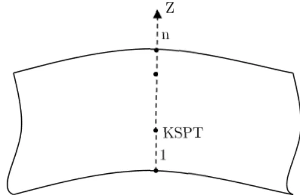
Figure 2: Shell reference surface.
3.2 Weak Form and Linearization
The weak form of equilibrium equations is given as C0
Ct
1 2
3
Initial configuration C0 Current configuration Ct
n
1
2
S1 S2
z y
3 3int V ij ij V
W
dV
e z dV (10)where are the in-plane stresses and 3 are the transverse shear stresses.
Performing the integration through the thickness of the shell, the weak form becomes
ext 0A
W
e N. .M.T dA W (11)where Wext is the external virtual work. e, and are the variations of the membrane, bending
and shear strains vectors. N, M and T are the membrane, bending and shear stresses resultants witch are expressed as
11 /2 22 /2 12 h h dz
N ,
11 /2 22 /2 12 h
h z dz
M , /2 13
/2 23 h h dz
T (12)The stress resultants and strain fields in Eqs. (11) and (12) can be grouped to form the generalized resultant stresses and generalized strains as
N R M T , e (13)
Using Eqs. (12) and (13), R and are related by the following equation
T
R H ,
0 0
0 0
m mb
T mb bb
s H H
H H H
H
(14)
/ 2
2
/ 2
, , h 1, ,
m mb bb
h z z dzH H H H , Hs K
hh/ 2/ 2Hdz (15)where H and H are in plane and out-of-plane linear elastic sub-matrices, which can be expressed in the Cartesian system as
2 1 0 1 01 0 0 1 / 2
z E z z z z
H ,
1 00 1 2 1 E z z H (16)where E z
and
z are the Young's modulus and the Poisson's ratio respectively. In Eq. (15), K is the shear correction matrix computed based on the work of Hajlaoui et al. (2015).The weak form of the equilibrium equation, Eq. 12, can be rewritten as a function of the nodal displacement vector Un
T
0n A ext n
Equation 17 defines the non-linear shell problem, which can be solved by the Newton iterative procedure. The consistent tangent operator for the Newton solution procedure can be constructed by the directional derivative of the weak form in the direction of the increment Un. The tangent
operator is decomposed, in a straight practice, into material and geometric parts as follows
T
int n M G n
W
U K K U (18)
where KM and KG are the material and geometric stiffness matrices respectively. Indeed, the
geo-metric part results from the variation of the virtual strains while holding stress resultant constant. The material part of the tangent operator results from the variation in the stress resultants while holding virtual strains constant. For the configuration update, the exact procedure for the nodes displacement vectors is additively constructed. However, for the nodal director field an exact update scheme is used based on finite rotation using exponential matrix.
3.3 Through-Thickness Integration and UMAT Interface
Numerical integration through the thickness of shell elements is needed to compute Eqs (12) and (15). Two types of numerical integration can be used: Gauss and Simpson integration. The number of the through-thickness integration points (n), necessary for an accurate analysis of FGM structure using shell elements, must be well chosen. A small number of integration points can create an additional error of the numerical results. The different shells are modeled with the standard structural shell elements, S4. This type of element is quadrilateral 4-nodes elements with three rotational and three translational degrees of freedom per node. This element is based on FSDT. The shell formulation of this element is derived using finite-membrane strain. This element is widely used for industrial appli-cations, as it is suitable for thin to moderately thick shell structures. Results, based on the FSDT of shell elements are obtained including an automatic calculation of the shear correction factors as in Hajlaoui et al. (2015).
In ABAQUS the integration points through the thickness of the shell are numbered consecutively, starting with point (1) to point (n). If Simpson’s rule is used, point 1 is exactly on the bottom surface of the shell, Fig. 3. If Gauss quadrature is used, it is the point that is near to the bottom surface, ABAQUS (2013).
Figure 3: Through-thickness integration, Simpson’s rule.
1
.
KSPT nZ
For each integration point through the thickness of the shell, number KSPT, ABAQUS make a call of UMAT subroutine, Table 1. More details can be found in ABAQUS (2013).
Loop over thickness points integration
Call UMAT(….DDSDDE, STRESS, KSPT…)
Compute parametric coordinate
KSPT
: 1 KSPT 1 Compute reel coordinate
Z
KSPT
:2 KSPT 2
h h
Z
Compute Stiffness matrix: DDSDDE
ZKSPT
Compute stress tensor: STRESS
ZKSPT
End Loop
Table 1: Through-thickness integration.
4 NUMERICAL RESULTS
The effectiveness of the developed geometric non-linear solution procedure is evaluated through sev-eral non-trivial structure problems static responses which are compared with literature. Numerical study is conducted using the UMAT subroutine implemented into ABAQUS. For all numerical ex-amples, the number of Simpson integration points through the thickness of the shell is equal to 25.
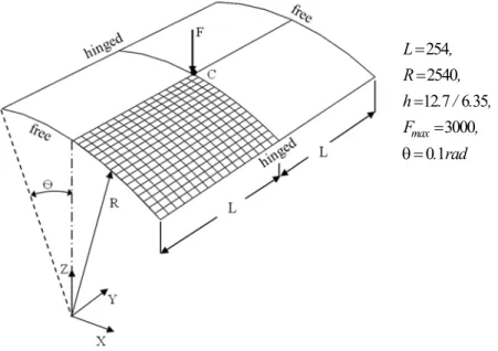
4.1 Hinged Cylindrical Roof Subjected to a Concentrated Load
In this section, the non-linear analysis of isotropic cylindrical shell subjected to a concentrated load is provided. The geometric properties of the panels are gathered in Fig.4, (Frikha and Dammak 2017; Sze et al. 2004; To and Wang 1998; Brank et al. 1995).
254 2540 12 7 6 35
3000 0 1 max
L ,
R ,
h . / . ,
F ,
. rad
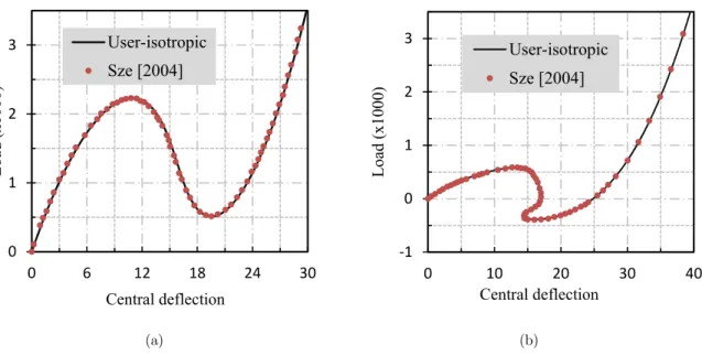
On one hand, this numerical example is considered with an isotropic material with the following material properties: Young’s modulus E3102 75. , Poisson‘s ratio 0 3. . Owing to symmetry, only one quarter of the physical domain is modeled. A convergence study indicates that the use 16x16 nodes is appropriate. This problem is solved numerically using Riks solution method adopted in ABAQUS, ie, we adopt the cylindrical arc-length procedure to obtain the numerical solutions. The total number of load increments (NINC) used in this test to obtain the plotted data is equal to 50. Figs. 5a and 5b illustrate the center deflection of the cylindrical roof as a function the applied load. The thickness was fixed to 12.7 and 6.35, respectively. For comparison purposes, solutions reported in literature are also plotted (Sze et al. 2004). A good correlation is depicted between the present results and those from literature. The thick panel exhibits standard limit points. However, in Fig. 5b one can notice complex equilibrium curves with snap-through and snap back behavior. This is a particular problem known as snapping behavior (Arciniega and Reddy 2007a; Payette and Reddy 2014). One can deduce that the complexity of the equilibrium paths of the panel increases as the shell thickness h is reduced.
(a) (b)
Figure 5: Load- deflection curves of the hinged cylindrical roof: a) h=12.7 mm, b) h=6.35mm.
On the other hand, in Fig. 6, we plot the non-linear mechanical response of FG metal-ceramic panels shallow hinged cylindrical roof. The FGM structure properties are the triplet
E , E ,m c
;70
m
E GPa and Ec168GPa which denote the Young’s modulus of the metal and ceramic compo-nents, respectively. The Poisson ratio for both metal and ceramic is assumed to be constant and equal to 0 3. .
Loa
d
(x1000
)
Central deflection User-isotropic Sze [2004]
‐
Loa
d
(x1000
)
Figure 6: Load- deflection curves of functionally grated metal-ceramic panels shallow hinged cylindrical roof, h= 12.7 mm, FGM (a=1, b=0.5, c=2).
According to Fig. 6, the pattern of the central deflection curves is similar to that of the isotropic and homogeneous shell, as expected. For instance, for the ceramic panel, the applied load increases until a deflection of 10 mm. Then it declines until a deflection of 20 mm. After that, the load increases monotonically with deflection. It is plausible that the applied load to ceramic panel is higher than that of metal due to the high stiffness of ceramic. Results shown in Fig 6 are visually in good agree-ment with the solutions presented by Arciniega and Reddy (2007b) as well as deflection curves in Frikha and Dammak (2017), Payette and Reddy (2014).
4.2 Case of Ring Plate
The ring plate geometry, which is shown in Fig. 7 was analyzed in Frikha and Dammak (2017); Sze et al. (2004) and Buechter and Ramm (1992), among others. The inner and the outer radius are denoted by r=6 m and R=10 m, respectively.
The ring is considered thin with a thickness h=0.03 m. The material is considered isotropic with the Young’s modulus Em 2 1 10. 8kN / m2 and the Poisson’s coefficient equal to zero. The ring plate
is loaded at its free edge, the other edge being fully clamped. The maximum applied load at the free edge is fixed to 6 kN/m. In this test, computation is performed with 60 load steps. The load factor, f , vs displacement diagram at points A, B and C (Fig. 8) shows the displacement components in the out-of-plane direction of the undeformed plate. Displacements agree very well with results reported in Frikha and Dammak (2017), Buechter and Ramm (1992) and Wriggers and Gruttmann (1993).
Loa
d
(x1000
)
Central deflection
(a) (b)
Figure 7: Initial and deformed configurations: the ring plate loaded with the line force qmax. a) Initial geometry. b) Deformed configuration of FGM plate, displacement U2 according to the loading direction (n=2), Fmax= 8 KN.
Figure 8: Load deflection curve of the isotropic ring plate.
In Figs. 9 and 10, we plot the non-linear mechanical response of FG metal-ceramic ring plate. The load force is fixed to 8kN. Herein, computation is performed with 80 load steps. The FGM structure properties are the triplet
E , E ,m c
; Em 70GPa, Ec151GPa and 0 3. . Results ofshear load vs displacement for various power law index at the two characteristic points A and B are well correlated with Arciniega and Reddy (2007a, 2007b). The deformed configuration of a FGM annular plate for n=2 is shown in Fig. 7b. A large displacement is depicted at load F=8kN.
‐
Lo
ad
fac
to
r
f
Displace e t
A: Prese t
A: Frikha [ ]
B: Prese t
B: Frikha [ ]
C: Prese t
Figure 9: Load-Displacement curve of the ring plate at point A.
Figure 10: Load-Displacement curve of the ring plate at B.
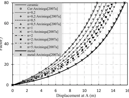
4.3 Hyperboloidal FG Shell
A hyperboloidal FG shell under two inward and outward point loads (Fig. 11a) is considered to evaluate the non-linear geometrically problem (Arciniega and Reddy 2007a, 2007b; Rezaiee-Pajand
Fa
ct
or
f
Displacement at A (m)
ceramic
Cer:Arciniega[2007a] n=0,2
n=0,2:Arciniega[2007a] n=0,5
n=0,5:Arciniega[2007a] n=1
n=1:Arciniega[2007a] n=2
n=2:Arciniega[2007a] n=5
n=5:Arciniega[2007a] metal
metal:Arciniega[2007a]
Fac
to
r
f
Displacement at B(m) cera ic
cer:Arci iega[ a]
= ,
= , :Arci iega[ a]
= ,
= , :Arci iega[ a]
=
= :Arci iega[ a]
=
= :Arci iega[ a]
=
= :Arci iega[ a]
etal
and Arabi 2016; Balah and Al-Ghamedy 2002; Wagner and Gruttmann 1994; Basar et al. 1993; Dammak et al. 2005), among others. The material and geometry properties of the shell are given in Table 2.
R1 R2 H h qmax
7.5 15 20 0.04 600 kN
FGM
Ceramic E=151 GPa = 0.3
Aluminum E=70 GPa = 0.3
Table 2: The geometrical characteristics of the hyperboloidal FGM shell.
(a) (b)
Figure 11: Hyperboloidal FGM shell subjected to alternating radial forces: a): Geometry properties, b): Deformed configuration, radial displacement U3 of the hyperboloidal FG shell (n=1).
The radius equation of the hyperboloid shell is given as:
: 1 1 203 2z R z R
(19)
Owing to symmetry, only one eighth of the shell is considered. The shell was analyzed using 10x20 S4 elements. The incrementally increased load reached a maximum of Pmax = 600.
(a) (b)
Figure 12: Load-radial displacement curves of hyperboloid shell with FGM material at points A and D (NINC=50).
(a) (b)
Figure 13: Load-radial displacement curves of hyperboloid shell with FGM material at points B and C (NINC=50).
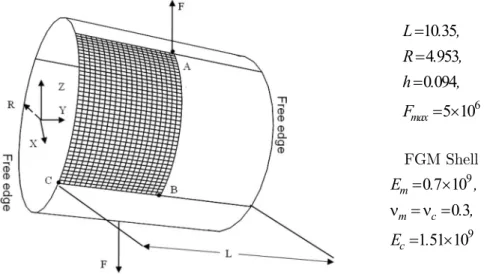
4.4 Case of Pulled Cylinder
In this section, the pulled cylinder problem is considered for non-linear shell analysis. It is concerned with the deformation of an open-ended cylinder FGM shell, under the action of two outward forces 180° apart. Using symmetry, only one eighth needs to be modeled with 20x40, S4 elements. This test is non-trivial which was considered in Arciniega and Reddy (2007a), Sze et al. (2004, 2002a, 2002b),
‐ ‐ ‐ ‐ ‐
Loa
d
(kN
)
Displacement at A (m) ceramic n=0,2 n=0,5 n=1 n=5 metal
‐ , ‐ , ‐ , ‐ ,
Loa
d
(kN
)
Displacement at D (m) ceramic n=0,2 n=0,5 n=1 n=5 metal
Loa
d
(kN
)
Displacement at B (m)
cera ic = , = , = =
etal
Loa
d
(kN
)
Displacement at C (m)
cera ic = , = , = =
Brank et al. (1995), Sansour et al. (2000), Gruttmann et al. (1989); Peng and Crisfield (1992) and Park et al. (1995). The initial and meshing configuration are shown in Fig. 14.
6
10 35
4 953
0 094
5 10
maxL
. ,
R
.
,
h
.
,
F
FGM Shell 9
9 0 7 10
0 3 1 51 10
m
m c
c
E . ,
. ,
E .
Figure 14: The open-end FGM cylinder shell subjected to radial pulling forces.
The load against the radial deflections at points A, B and C of the shell, are plotted in Figs. 15– 17. Results are in good agreement with those of Arciniega and Reddy (2007a). The deformed config-urations for a FGM shells under the maximum load is depicted in Fig. 18 for F=5 x10⁶ and n=5. It is also noticed that the response of the cylinder shell has two different regions: the first is dominated by bending stiffness with large displacements; the second, at load level of F = 5x10⁶, is characterized by a very stiff response of the shell. These results obtained by the present model are well correlated with findings of Arciniega and Reddy (2007a) and Sze et al. (2004).
Punc
hi
ng
forc
e
(x10000
)
Radial deflection at A ceramic
ceramic: Arciniega[2007a] n=0,2
n=0,2: Arciniega[2007a] n=1
n=1: Arciniega[2007a] n=5
n=5: Arciniega[2007a] metal
metal: Arciniega[2007a]
Figure 16: Radial displacement at point B (-UB) vs. pulling force of a FGM cylinder with free edges (NINC=200).
Figure 17: Radial displacement at point C (-UC) vs. pulling force of a FGM cylinder with free edges (NINC=200).
Figure 18: Deformed mesh configurations of cylinder shell with FGM material for n=5, radial displacement U3 of the pulled cylinder.
Pul
ling forc
e
(x10000)
Radial deflactiont at B
cera ic
cer: Arci iega[ a] = ,
= , : Arci iega[ a] =
= : Arci iega[ a] =
= : Arci iega[ a]
-U
BPul
ling forc
e
(x10000)
Radial deflection at C
cera ic
cer: Arci iega[ a] = ,
= =
etal
4.5 Pinched Cylinder FGM Shell
This example can be imagined as a pinched can of soda. The cylinder shell geometry is shown in Fig. 19a. The maximum applied load at the free edge is fixed to Fmax= 2x10⁶. The circumferential
periph-ery is fully clamped. The geometrical and material parameters are described in section 4.4. Owing to symmetry, one half of shell is modeled with a mesh size of 20x40 elements S4.
(a) (b)
Figure 19: Pinched cylindrical shell mounted on rigid diaphragms. a) Geometric properties, b) The deformed of the FGM shell.
Figure 20: Load-deflection curves of the pinched FGM cylindrical shell at A, (Fmaxi =2x10⁶) (NINC=200).
, , , ,
Pi
nc
he
d
forc
e
(x10
6)
Displacement at A ceramic
n=0,2 n=0,5 n=1 n=2 n=5 metal
Figs. 20–22 show the load against the deflections at points A, B and C of the cylinder shell, respectively. The deformed geometry under the maximum load is described in Fig. 19b. It is noticed that the response of the cylinder shell, at load level of F = 2x10⁶, is subjected to large displacements. Tables 3-5, given in appendix, lists the deflections at point A, B and C for different n.
Figure 21: Load-deflection curves of the pinched FGM cylindrical shell at B, (Fmaxi =2x10⁶) (NINC=200).
Figure 22: Load-deflection curves of the pinched FGM cylindrical shell at C, (Fmaxi =2x10⁶) (NINC=200).
,
,
,
,
‐ ,
,
,
Pi
nc
he
d
forc
e
(x10
6)
Displacement at B
ceramic n=0,2 n=0,5 n=1 n=2 n=5 metal
UB
, , , ,
‐ , , , ,
Pi
nc
he
d
forc
e
(x10
6)
Displacement at C x10
ceramic n=0,2 n=0,5 n=1 n=2 n=5 metal
4.6 Case of Semi-Cylindrical FG Shell Loaded with an End Pinching Force
In this section, a semi-cylindrical FG shell subjected to an end pinching force is considered. The cylindrical shell geometry is show in Fig. 23a. The maximum applied load at the middle is taken to be Fmax= 1x 10⁶. Using symmetry, only one quarter needs to be modeled with 28 x 28 S4 elements,
Fig. 23b. The cylinder length is L = 3.048 and the radius R=1.016 with thickness h=0.03. The present problems have been considered in Refs. (Sze et al. 2004, 2002a, 2002b; Brank et al. 1995; Klinkel et al. 1999 and Fontes et al. 2003).
The load–deflection curve at point A of isotropic material is shown in Fig. 24 and compared with the reference solution of Sze et al. (2004). Material properties are: E 2 068 10. 7and
0 3. .(a) (b)
Figure 23: Semi-cylindrical FGM shell subjected to a pinching force. a) Geometry properties, b) The deformed 28x28 mesh of the pinched under maximum load for cylinder FGM shell (n=0.2).
Figure 24: Load-deflection curves of the pinched isotropic cylindrical shell at A, (F =2000), (NINC=100).
, ,
, , , ,
Loa
d
(x1000
)
Displacement at A (m) Present
In Fig. 25, we plot the load–deflection curves for the loading point A of functionally grated metal-ceramic panels. The FGM structure properties are the triplet
E , E ,m c
;9
0 7 10 m
E . and 9
1 51 10 c
E . and
0 3. . The curves are presented for different power-law index (n=0.2, 0.5, 2, 5 and 10). It is plausible that the load–deflection curve of the pure ceramic shell exhibits the highest value that of metal.Figure 25: Load-deflection curves of the pinched FGM cylindrical shell at A, (Fmaxi =1x10⁶) (NINC=100).
4.7 Hemispherical FGM Shell with 18° Hole
The pinched hemisphere problem is considered with an 18° hole at the top subjected to two inward and two outward forces at points A and B at 90° intervals. This example can be used to assess the performance of the finite element employed, regarding the shear locking behavior in doubled curved shells. From the geometrical symmetry of the sphere, only one quarter needs to be modeled. Fig. 26 presents geometry and material properties of the shell. Symmetry conditions with 20x20 S4 meshes are used in this example. The problem has been considered in Refs. (Kim et al. 2008; Sze et al. 2004, 2002a, 2002b; Buechter and Ramm 1992; Sansour and Kollmann 2000; Park et al. 1995; Saleeb et al. 1990; Simo et al. 1990a, 1990b; Lee et al. 1984; Basar et al. 1992; Sansour and Bufler 1992; Betsch and Stein 1995; Hauptmann and Schweizerhof 1998; Providas and Kattis 1999; Hong et al. 2001 and Kim et al. 2003), among others. In one hand, we consider the case of isotropic material. The loads are increased by a factor of 490 comparing with results by Kim et al. (2008), as shown in Fig. 27.
, , , ,
Loa
d
(x1000
0)
Displacement at A ceramic
4 953
0 04
490
max
R
.
h
.
F
7
6 825 10
.
1
E
03
.
Figure 26: Description of the hemispherical shell geometry.
Figure 27: Load-deflection curves of the hemispherical shell subjected to radial forces at A and B. WA and UB: radial displacements according to the load direction, (NINC=100).
On the other hand, the load against the radial deflections at points A and B of the FG metal-ceramic hemispherical shell, are plotted in Fig. 28. The load force is fixed to 8 x 10⁵. The FGM structure properties are the triplet
E , E ,
m c
;9
70 10
m
E
,E
c
151 10
9 and
0 3
.
. Resultsof shear load vs displacement for various power law index at the two characteristic points A and B are plotted, Fig. 28. The addition of a ceramic volume fraction increases the stiffness of the hemi-spherical shell. The load–displacement curves are located between those of the metal and ceramic
Loa
d
(x100)
Radial displacement at point A and B
Prese t Ki [ ]
Poi t B ‐UB
shells. The deformed configurations for a FGM shells under the maximum load is portrayed in Fig. 29 for n=0.2.
Figure 28: Load-deflection curves of the pinched FGM hemispherical shell at A and B, (Fmaxi =8x10⁵), (NINC=100).
Figure 29: Initial and deformed mesh configurations, radial displacement U3 of the hemisphere (n=0.2).
5 CONCLUSION
In this research, a numerical approach to analyze the geometric non-linear static response of FG shells is presented. The material properties are introduced according to the integration points via the im-plementation of the user-material UMAT subroutine into ABAQUS software. To the best knowledge of the authors, there are no further accessible documents in literature on ABAQUS implementation of static and geometrical non-linear response of FG shells. The main contribution of the present
Loa
d
(x1000
00
)
Displacement at A and B ceramic
n=0.2 n=2 n=10 metal
Point A (WA)
research is to form a convenient basis, for subsequent comparison, to analyze the geometrically non-linear FG structures. Seven popular nonnon-linear structure problems were studied, and compared with those reported in the literature. The accuracy of the developed nonlinear solution procedures is well assessed and the present results corroborate the existent reference data. A future track of work intro-ducing plastic behavior of FG shell, will be the investigation of both geometrical and material non-linear FG structure response.
References
ABAQUS User’s Manual (2013). ABAQUS Version.6.13.
Alinia, M.M., Ghannadpour, S.A.M., (2009). Nonlinear analysis of pressure loaded FGM plates. Composite Structures 88:354-359.
Ansari, R., Hasrati, E., Shojaei, M. F., Gholami, R., Mohammadi, V., Shahabodini, A., (2016). Size-Dependent Bend-ing, Buckling and Free Vibration Analyses of Microscale Functionally Graded Mindlin Plates Based on the Strain Gradient Elasticity Theory. Latin American Journal of Solids and Structures 13: 632-664.
Arciniega, R.A., Reddy, J.N., (2007a). Large deformation analysis of functionally graded shells. International Journal of Solids and Structures 44:2036-2052.
Arciniega, R.A., Reddy, J.N., (2007b). Tensor-based finite element formulation for geometrically nonlinear analysis of shell structures. Computer Methods in Applied Mechanics and Engineering 196:1048-1073.
Asemi, K., Salami, S.J., Salehi, M., Sadighi, M., (2014). Dynamic and static analysis of FGM skew plates with 3D elasticity based graded finite element modeling. Latin American journal 11:504-533.
Balah, M., Al-Ghamedy, H.N., (2002). Finite element formulation of a third order laminated finite rotation shell element. Computers & Structures 80:1975-1990.
Basar, Y., Ding, Y., (1992). Finite-rotation shell elements for the analysis of finite-rotation shell problems. International Journal for Numerical Methods in Engineering 34:165-169.
Basar, Y., Ding, Y., Schultz, R., (1993). Refined shear-deformation models for composite laminates with finite rotations. International Journal of Solids and Structures 30:2611-2638.
Betsch, P., Stein, E., (1995). An assumed strain approach avoiding artificial thickness straining for a non- linear 4-node shell element. International Journal for Numerical Methods in Engineering 11:899-909.
Brank, B., Damjanić, F.B., Perić, D., (1995). On implementation of a nonlinear four node shell finite element for thin multilayered elastic shells. Computational Mechanics 16:341-359.
Buechter, N., Ramm, E., (1992). Shell theory versus degeneration - a comparison in large rotation finite element analysis. Computer Methods in Applied Mechanics and Engineering 34:39-59.
Chi S.H., Chung Y.L., (2006). Mechanical behavior of functionally graded material plates under transverse load. part 2: Numerical results. International Journal of Solids and Structures 43:3675-3691.
Dammak, F., Abid, S., Gakwaya, A., Dhatt, G., (2005). A formulation of the non linear discrete Kirchhoff quadrilateral shell element with finite rotations and enhanced strains. Revue Européenne des Éléments Finis 14:7-31.
Duc, N.D., Quang, V.D., Anh, V.T.T., (2017). The nonlinear dynamic and vibration of the S FGM shallow spherical shells resting on an elastic foundations including temperature effects. International Journal of Mechanical Sciences 123:54-63.
Etemadi, E., Afaghi, Khatibi, A., Takaffoli, M., (2015). 3D finite element simulation of sandwich panels with a func-tionally graded core subjected to low velocity impact. Composite Structures 89:28–34.
Me-Frikha, A., Wali, M., Hajlaoui, A., Dammak, F., (2016). Dynamic response of functionally graded material shells with a discrete double directors shell element. Composite Structures 154:385-395.
Frikha, A., Dammak, F., (2017). Geometrically non-linear static analysis of functionally graded material shells with a discrete double directors shell element. Computer Methods in Applied Mechanics and Engineering 315:1-24.
GhannadPour, S.A.M., Alinia, M.M., (2006). Large deflection behavior of functionally graded plates under pressure loads. Composite Structures 75:67-71.
Gruttmann, F., Stein, E., Wriggers, P., (1989). Theory and numerics of thin elastic shells with finite rotations. Ingenieur-Archiv 59:54-67.
Hajlaoui, A., Jarraya, A., El Bikri, K., Dammak F., (2015). Buckling analysis of functionally graded materials struc-tures with enhanced solid-shell elements and transverse shear correction. Composite Strucstruc-tures 132:87-97.
Hajlaoui, A., Triki, E., Frikha, A., Wali, M., Dammak, F., (2017). Nonlinear dynamics analysis of FGM shell structures with a higher order shear strain enhanced solid-shell element. Latin American Journal of Solids and Structures 14:72-91. Hasselman, D.P.H., Youngblood, G.E., (1978). Enhanced thermal stress resistance of structural ceramics with thermal conductivity gradient. Journal of the American Ceramic Society 61(1,2):49-53.
Hauptmann, R., Schweizerhof, K., (1998). A systematic development of solid-shell element formulations for linear and nonlinear analyses employing only displacement degrees of freedom. International Journal for Numerical Methods in Engineering 42:49-69.
Hong, W.I., Kim, J.H., Kim, Y.H., Lee, S.W., (2001). An assumed strain triangular curved solid shell element formu-lation for analysis for plates and shells undergoing finite rotations. International Journal for Numerical Methods in Engineering 52:747-761.
Hosseini Kordkheili, S.A., Naghdabadi, R., (2007). Geometrically nonlinear thermoelastic analysis of functionally graded shells using finite element method. International Journal for Numerical Methods in Engineering 72:964-986. Hosseini Tehrani, P., Talebi, M., (2012). Stress and temperature distribution study in a functionally graded brake disk. International Journal of Automotive Engineering 2(3):172-179.
Kattimani, S.C., Ray, M.C., (2015). Control of geometrically nonlinear vibrations of functionally graded magneto-electro-elastic plates. International Journal of Mechanical Sciences 99:154-167.
Kim, C.H., Sze, K.Y., Kim, Y.H., (2003). Curved quadratic triangular degenerated- and solid-shell elements for geo-metric nonlinear analysis. International Journal for Numerical Methods in Engineering 57:2077-2097.
Kim, K.D., Lomboy, G.R., HAN, S.C., (2008). Geometrically non-linear analysis of functionally graded material (FGM) plates and shells using a four-node quasi-conforming shell element. Journal of Composite Materials 42:485-511. Klinkel, S., Gruttmann, F., Wagner, W., (1999). A continuum based three-dimensional shell element for laminated structures. Computers & Structures 71:43-62.
Lee, S.J., Kanok-Nukulchai, W., (1998). A nine-node assumed strain finite element for large deformation analysis of laminated shells. International Journal for Numerical Methods in Engineering 42:777-798.
Lee, Y.Y., Zhao, X., Liew, K.M., (2009). Free vibration analysis of functionally graded plates using the element-free kp-ritz method. Journal of Sound and Vibration 319:918-939.
Mantari, J.L., Monge, J.C., (2016). Buckling, free vibration and bending analysis of functionally graded sandwich plates based on an optimized hyperbolic unified formulation. International Journal of Mechanical Sciences 119:170-186. Mao, Y., Fu, Y., Fang, D., (2013). Interfacial damage analysis of shallow spherical shell with fgm coating under low velocity impact. International Journal of Mechanical Sciences 71:30–40.
Niino, M., Maeda, S., (1990). Recent development status of functionally gradient materials. International Iron and Steel Institute 30:699-703.
Park, H.C., Cho, C., Lee, S.W., (1995). An efficient assumed strain element model with six dof per node for geometri-cally nonlinear shells. International Journal for Numerical Methods in Engineering 38:4101-4122.
Payette, G.S., Reddy, J.N., (2014). A seven-parameter spectral/hp finite element formulation for isotropic, laminated composite and functionally graded shell structures. Computer Methods in Applied Mechanics and Engineering 278:664-704.
Peng, X., Crisfield, M.A., (1992). A consistent corotational formulation for shells using the constant stress/constant moment triangle. International Journal for Numerical Methods in Engineering 35:1829-1847.
Phung-Van, P., Nguyen-Thoi, T., Luong-Van, H., Lieu-Xuan, Q., (2014). Geometrically nonlinear analysis of function-ally graded plates using a cell-based smoothed three-node plate element (CS-MIN3) based on the C0-HSDT. Computer Methods in Applied Mechanics and Engineering 270:15-36.
Praveen, G.N., Reddy, J.N., (1998). Nonlinear transient thermoelastic analysis of functionally graded ceramic–metal plates. International Journal of Solids and Structures 35:4457-4476.
Providas, E., Kattis, M. A., (1999). A simple finite element model for the geometrically nonlinear analysis of thin shells. Computational Mechanics 24:127-137.
Reddy, J.N., (2000). Analysis of functionally graded plates. International Journal for Numerical Methods in Engineering 47:663-684.
Rezaiee-Pajand, M., Arabi, E., (2016). A curved triangular element for nonlinear analysis of laminated shells. Compo-site Structures 153:538-548.
Saleeb, A.F., Chang, T.Y., Graf, W., Yingyeunyong, S., (1990). A hybrid/mixed model for non-linear shell analysis and its applications to large-rotation problem. International Journal for Numerical Methods in Engineering 29:407-446. Sansour, C., Bufler, H., (1992). An exact finite rotation shell theory, its mixed variational formulation and its finite element implementation. International Journal for Numerical Methods in Engineering 34:73-115.
Sansour, C., Kollmann, F.G., (2000). Families of 4-nodes and 9-nodes finite elements for a finite deformation shell theory. An assessment of hybrid stress, hybrid strain and enhanced strain elements. Computational Mechanics 24:435-447. Simo, J.C., Fox, D.D., Rifai, M.S., (1990a). On a stress resultant geometrically exact shell model. Part III: computa-tional aspects of the nonlinear theory. Computer Methods in Applied Mechanics and Engineering 79: 21-70.
Simo, J.C., Rifai, M.S., Fox, D.D., (1990b). On a stress resultant geometrically exact shell model, Part IV: variable thickness shells with through-the-thickness stretching. Computer Methods in Applied Mechanics and Engineering 81:91-26.
Sze, K.Y., Zheng, S.J., (2002a). A stabilized hybrid-stress solid element for geometrically nonlinear homogeneous and laminated shell analyses. Computer Methods in Applied Mechanics and Engineering 191:1945-1966.
Sze, K.Y., Chan, W.K., Pian, T.H.H., (2002b). An eight-node hybrid-stress solid-shell element for geometric nonlinear analysis of elastic shells. International Journal for Numerical Methods in Engineering 55:853-878.
Sze, K.Y., Liua, X.H., Lob, S.H., (2004). Popular benchmark problems for geometric nonlinear analysis of shells. Finite Elements in Analysis and Design 40:1551-1569.
Thai, H.T., Kim, S.E., (2015). A review of theories for the modeling and analysis of functionally graded plates and shells. Composite Structures 128:70-86.
To, C.W.S., Wang, B., (1998). Hybrid strain-based three-node flat triangular laminated composite shell elements for vibration analysis. Journal of Sound and Vibration 211(2):277-291.
Wagner, W., Gruttmann, F., (1994). A simple finite rotation formulation for composite shell elements. Engineering Computations 11:145-176.
Wali, M., Hajlaoui, A., Dammak, F., (2014). Discrete double directors shell element for the functionally graded material shell structures analysis. Computer Methods in Applied Mechanics and Engineering 278:388-403.
Wali, M., Hentati, T., Jarraya, A., Dammak, F., (2015). Free vibration analysis of FGM shell structures with a discrete double directors shell element. Composite Structures 125:295-303.
Woo, J., Merguid, S.A., (2001). Non-linear analysis of functionally graded plates and shallow shells. International Journal of Solids and Structures 38:7409–21.
Wriggers, P., Gruttmann, F., (1993). Thin shells with finite rotations formulated in biot stressed: Theory and finite element formulation. International Journal for Numerical Methods in Engineering 36:2049-2071.
Yang, J., Shena, H.S., (2003). Non-linear analysis of functionally graded plates under transverse and in-plane loads. International Journal of Non-Linear Mechanics 38:467-482.
Yu, T.T., Yin, S., Bui, T.Q., Hirose, S., (2015). A simple FSDT-based isogeometric analysis for geometrically nonlinear analysis of functionally graded plates. Finite Elements in Analysis and Design 96:1-10.
Zhao, X., Liew, K.M., (2009). Geometrically nonlinear analysis of functionally graded shells. International Journal of Mechanical Sciences 51:131-144.
APPENDIX
F/Fmax ceramic n=0.2 n=0.5 n=1 n=2 n=5 metal
0.1 0.213 0.271 0.331 0.393 0.449 0.507 0.653
0.2 0.602 0.683 0.764 0.852 0.937 1.026 1.290
0.3 0.903 1.015 1.134 1.267 1.400 1.557 2.672
0.4 1.195 1.353 1.532 1.808 2.449 2.832 3.294
0.5 1.514 1.817 2.560 2.923 3.127 3.289 3.572
0.6 2.208 2.821 3.077 3.266 3.409 3.533 3.754
0.7 2.908 3.154 3.327 3.474 3.593 3.700 3.890
0.8 3.176 3.357 3.498 3.624 3.730 3.827 3.999
0.9 3.353 3.504 3.628 3.741 3.838 3.929 4.090
1 3.487 3.620 3.732 3.837 3.929 4.016 4.169
Table 3: Radial deflection at point A (-WA) of the pinched cylindrical shell.
F/Fmax ceramic n=0.2 n=0.5 n=1 n=2 n=5 metal
0.1 0.100 -0.021 -0.025 -0.030 -0.037 -0.044 -0.052
0.2 -0.064 -0.075 -0.087 -0.101 -0.115 -0.128 -0.153
0.3 -0.110 -0.128 -0.144 -0.155 -0.151 -0.124 0.424
0.4 -0.149 -0.155 -0.136 -0.056 0.277 0.533 0.882
0.5 -0.135 -0.051 0.348 0.599 0.750 0.873 1.106
0.6 0.137 0.527 0.714 0.858 0.969 1.066 1.260
0.7 0.590 0.773 0.907 1.024 1.118 1.205 1.380
0.8 0.790 0.931 1.044 1.147 1.234 1.314 1.480
0.9 0.928 1.050 1.152 1.246 1.328 1.406 1.566
1 1.035 1.146 1.240 1.330 1.410 1.485 1.642
F/Fmax ceramic n=0.2 n=0.5 n=1 n=2 n=5 metal
0,1 0,014 0,017 0,020 0,023 0,026 0,030 0,039
0,2 0,036 0,040 0,043 0,046 0,047 0,045 0,030
0,3 0,048 0,049 0,046 0,034 0,012 -0,024 0,068
0,4 0,040 0,022 -0,012 -0,070 -0,040 0,184 0,742
0,5 -0,010 -0,073 0,012 0,284 0,513 0,724 1,231
0,6 -0,099 0,186 0,455 0,714 0,935 1,138 1,623
0,7 0,259 0,549 0,809 1,061 1,278 1,478 1,956
0,8 0,570 0,852 1,105 1,355 1,571 1,770 2,249
0,9 0,835 1,111 1,362 1,611 1,828 2,029 2,513
1 1,067 1,340 1,590 1,841 2,061 2,263 2,754