Abstract—Computer-Aided Manufacturing technology has been widely used for three-axis CNC machining in industry for many years. However, there still have some problems on five-axis machining applications. The major problems are overcut, interference, and trajectory error due to coordinated rotating and translating motions. Therefore, to develop more accurate and efficient five-axis tool-path planning is an important need for CNC machining industry. This research proposes a new method to produce accurate tool paths and orientations for 5-axis machining. The research approach begins with the analysis of the contour error due to the combinational motion of rotation and translation. The tool path feed step and tool orientation can be controlled accurately according to the determined trajectory error. Taking a part for example, the result shows that the trajectory contour error is improved about 5 times, from 0.153 mm to 0.031 mm, by using conventional method and our proposed approach, respectively. The new method improves not only the max. contour error, but part surface smoothness.
Index Terms— Tool-Path Planning, Five-Axis Machining, Trajectory
I. INTRODUCTION
n order to achieve high accuracy, less cutting time, and machining variety, normally, additional 2 rotating axes are set up on top of traditional three-axis Computer Numeric Control (CNC) machine tool, which is called five-axis machines. Five-axis machining has many advantages compared to three-axis one, including higher metal removal rates, better surface finish, and more precise part surface in one setup [Sprow 1993, Jensen and Anderson 1992, Vickers and Quan 1989]. Most Computer-Aided Design and Computer-Aided Manufacturing (CAD/CAM) approaches for five-axis machining assume a constant tool orientation along each segment. The more advanced methods assume a linear change in the tool orientation between successive end-points. The constant orientation algorithm causes severe roughness around the end-points along the surface since the orientation changes are abrupt at these points. The linear orientation algorithm produces a better surface, but still interpolates the orientations inaccurately between end points since the change in the orientation is not necessarily linear,
Rong-Shine Lin*, Associate Professor in the Advanced Institute of Manufacturing for High-tech Innovations and Department of Mechanical Engineering, National Chung Cheng University, Chia-Yi, Taiwan 62102, R.O.C. (corresponding author e-mail: [email protected], phone: +886-5272-0411 ext. 33300; fax: +886-5272-0589.
Cheng-Bing Ye, Graduate student in the Department of Mechanical Engineering, National Chung Cheng University, Chia-Yi, Taiwan 62102, R.O.C.
which causes part surface errors.
Computer-Aided Manufacturing (CAM) technology has been widely used for three-axis CNC machining in industry for many years. However, there still have some problems on five-axis machining applications. The major problems are overcut, interference, and trajectory error due to the coordinated rotating and translating motions. Therefore, to develop more accurate and efficient method for five-axis tool-path planning is an important need for CNC machining industry.
The tool motion between 2 cutter contact (CC) points for five-axis CNC machine tools, including rotating axes, is a nonlinear trajectory and substantially causes overcuts or undercuts. The error between the desired trajectory and the actual path is called contour error. This error depends on the setup of the machine, the distance between the center of rotating axis and the workpiece, and the incremental angle of the rotating axis. This research analyzes the tool-motion contour error for table-tilt type five-axis machine tool.
The conventional approach to reduce the tool-motion contour error uses more line segments to approximate the desired trajectory. However, this method makes the machining time increasing and subsequently causes the machine table vibrating if the federates are not controlled properly. This research proposes a new method to produce accurate tool paths and orientations for five-axis machining. The proposed approach begins with the analysis of the contour error due to the combinational motion of rotation and translation. The tool path feed-step and tool orientation can be controlled accurately according to the pre-determined trajectory error. Taking a part for example, the result shows that the tool-motion contour error is improved about 5 times, from 0.153 mm to 0.031 mm, by using conventional method and our proposed approach, respectively. The new method improves not only the max. contour error, but part surface smoothness.
II. TOOL PATH PLANNING
STereoLithography (STL) model has been widely used for Computer-Aided Design (CAD) part model in many manufacturing applications, such as machining, rapid prototyping, and mold/die making. This research uses STL model to describe a machining part. The reason for using STL files is that the file format is simple and most CAD systems, such as AutoCAD, ProE, and Solidworks, provide this format for product design.
Accurate Trajectory Control for Five-Axis
Tool-Path Planning
Rong-Shine Lin* andCheng-Bing Ye
A. STL model
The STL format is a tessellation representation, which defines a 3-D object by a series of triangular facets. Each triangular facet is defined by three vertices and a unit normal vector for the facet where the vector direction indicates the outside of the object. Figure 1 shows a triangular facet where P1, P2, and P3 are vertices and [Vx, Vy, Vx] is the facial unit normal vector. Figure 2 shows a half sphere part example in STL model.
P1(X1,Y1,Z1)
P2(X2,Y2,Z2) P3(X3,Y3,Z3)
[Vx,Vy,Vz]
Figure 1. The triangular facet and its data format
Figure 2. the STL Part model
B. Cutter Contact Path Calculation
This research applies the Cartesian tool-path planning method [Bobrow, 1985; Choi et al., 1988], which begins with the cutting paths to be parallel straight lines on the xy-plane, either in x-axis or y-axis direction. Then, the cutting paths on the part surface can be obtained by projecting these lines back to the part surface. In other words, the cut-path is the intersection trajectory between the part surface and a vertical plane. The intersection point is called the cutter contact (CC) points or trajectory. Figure 3 shows the cut-path planning scheme using this method.
X
Y Z
Vertical plane Part surface
Intersection curve
Figure 3. Illustration of Cartesian tool-path planning method.
In order to determine the next cut-path precisely, the cut-path intervals along the previously determined cut-path must be calculated, depending on part surface geometry. The
minimum cut-path interval is selected for placing the next cut-path. The reason for choosing the minimum interval is to keep the scallop heights under the required tolerance. Scallop height is an indicator for part surface roughness.
C. CC path interval
When the milling operation is completed, scallops remain on the finished surface, as shown in Fig. 4. For a given allowable scallop height (h) the CC path interval can be obtained by using the Pythagoras theorem
2 c 2 2
c (r h)
2 L
r ⎟ + −
⎠ ⎞ ⎜ ⎝ ⎛
= (1)
where L denotes the CC path interval,
r
cdenotes the radius of a ball-end cutter, and h denotes the allowable scallop height. Through rearranging, the CC path interval L can be obtained,h r 8 ) h r ( r 2
L c
2 c 2
c − − ≅
= (2)
h
L
Figure 4. The scallop height (h) on the finished part surface
The assumption in the approximation of Eq. (2) is that h << r, which is reasonable, since typically r > 1 mm and h < 0.01 mm (depending on the surface finish requirement). Equation (2) is an analytical solution of the CC path interval in flat-plane machining.
D. Tool Path Calculation
The intersection between the part surface and a vertical plane is the CC point or trajectory. If the part surface is a STL model, the CC points can be obtained by calculating the intersections of the plane and triangular facets, as shown in Fig. 5. The mathematic problem becomes to find the intersection between 2 lines. This research uses linear interpolation method to solve the intersections.
Vertical plane Triangular facet
(x2,y2,z2)
(x1,y1,z1)
The tool path, also called cutter location (CL) path or trajectory, describes the cutter’s center position. For a ball-end cutter, mathematically it is the offset of the CC point along the part surface normal direction with a distance of cutter radius. Therefore, the cutter location (P’) can be calculated as below,
) Nz , Ny , Nx ( N r ) z , y , x ( P ) z , y , x ( '
P 1 1 1 = 0 0 0 + ⋅ 0 0 0 (3)
where P is the CC point, r is the cutter radius, and Nv is the unit vector of surface normal that is given in STL file.
The determined CC path on the part surface is continuous. However, a gap will be generated between 2 successive CL segments, which are offsetting from CC segments. Figure 6 shows the gap after CC path offset. The gap on the CL path will cause overcuts if the CL point 2 and 4 were connected with a straight line as a CL segment. To overcome this problem, new CL segments is needed for the gap inserting. To do so, a new normal vector Nv3, called co-edge normal, between 2 adjacent triangular facets is calculated. Figure 7 shows the scheme of inserting a new position P3 and the co-edge normal. The co-edge normal is an arithmetic mean of 2 adjacent triangle-facet normals. The length of co-edge normal R can be calculated as,
) 2 / cos(
r R
θ
= (4)
where r is the cutter radius and
θ
is the angle between 2 facet normals and can be calculated as,) N N
N N ( cos
2 1
2 1
1 ⋅
=
θ − (5)
Figure 6. The gap after the CC point offset
Original facet normal vector Co-edge normal on the vertex
P3
θ/2
Figure 7. The co-edge normal between 2 adjacent triangular facets
III. TOOL TRAJECTORY ERROR ANALYSES
The tool motion between 2 cutter contact points for five-axis CNC machine tools, including rotating axes, is a nonlinear trajectory and substantially causes overcuts or undercuts. Figure 8 illustrates the error (ε), resulting from the linear movements of coordinated rotating and translating axes. The error between the desired trajectory and the actual path is called contour error. This error depends on the setup of the machine, the distance between the center of rotating axis and the workpiece, and the incremental angle of the rotating axis. This research analyzes the tool-path contour error for a table-tilt type five-axis machine tool, as shown in Fig. 9.
ε
Orientation 1 Orientation 1
Orientation 2
θ
Figure 8. The contour error due to coordinated rotating and translating motions
Figure 9. the structure of the table-tilt type 5-axis machine tool
A. Contour error for Tool Trajectory
The contour error for five-axis tool trajectory can be estimated as,
A 0 f T
R ) ( Cos R e
e ≈ ⋅ β
(6)
whereefis the conventional cord error for three-axis circular machining; Rois the distance between the CC point and the rotating axis center;RAis the radius of the circular motion; β
is the angle at beginning cut. If the trajectory is an arbitrary curve instead of a circle, RAis the instantaneous radius of curvature and the ef is the cord error, counting for the approximated instantaneous circle. eT in Eq. (6) is the max. contour error for a five-axis tool trajectory.
In order to illustrate the contour errors, which is due to the coordinated motions for translating and rotation axes, a circular arc part geometry is used for demonstration. For five-axis end-milling, the tool orientations are controlled to STL model
be perpendicular to the part surface during machining. The machine setup for this machining is a table-tilt type five-axis machine, as shown in Fig. 9. To produce this 2-D circular arc, one rotating axis (A axis) and 2 translating axes (Y and Z axes) coordinated motions are needed.
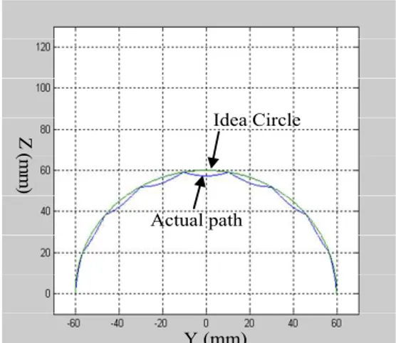
The part is a half circle with 60 mm in radius, as shown in Fig 10. A ball-end cutter with 10 mm diameter is used for the cutting tool. The tool orientation, which is perpendicular to the part surface, can be calculated as,
y
O =sin(2πu) (7)
z
O =cos(2πu)
where u is the parameter between 0 and 1. This research uses Matlab programming software to simulate the actual tool trajectory for Y-Z-A axis coordinated motions. In order to see the error clearly, this research uses a large incremental angle ( o
20 ) for a-axis motion, as shown in Fig. 10. The green curve is the desired circular arc and the blue trajectory is the actual tool path. The contour error can be determined and shown in Fig. 11. In this case, the maximum contour error is 2.7 mm, which is an overcut and happens at 90 degree of the circle.
Idea Circle
Actual path
Y (mm)
Z
(
mm)
Figure 10. The idea circle and the resulted real tool path
Circular angle (degree)
Cont
our
er
ro
r (
mm)
Figure 11. The contour error distribution along circular angle
The conventional approach to reduce the above contour error uses more line segments to approximate the desired curve. However, this method makes the machining time increasing and subsequently causes the machine table vibrating if the federates are not controlled properly.
The tool trajectory contour error depends on the machining part location and the incremental step-size on the path. From the analyzed results, as shown in Fig. 12, the larger distance
for the part location, the bigger contour error will be. In addition to the part location that affects the contour error, the tool-path step size is also causing the contour error. The longer step-size causes larger rotating step-angle. Likewise, as shown in Fig. 12, the larger incremental rotating step-angle, the bigger contour error is. This contour error analyses can be used to produce more accurate five-axis tool paths.
Ro=200
Ro=150
Ro=100
Ro=50
Step angle (degree)
Con
tou
r e
rr
o
r (m
m
)
Figure 12. The contour errors for different rotating step-angles
B. Radius of curvature of the part surface
This research uses an approximating method to find the instantaneous radius of curvature for a STL part surface. The instantaneous circular center (Cp) can be calculated from the intersection of 2 surface normal lines for 2 successive vertices (P1 and P2), as shown in Fig. 13. The distance between the circular center and the vertex is the instantaneous radius of curvature. As shown in Fig 13, R1 and R2 are instantaneous radii of curvature for vertices P1 and P2, respectively. Usually R1 and R2 are not equal since the STL model is an approximated surface representation. The average radius between R1 and R2 is used for the circular center determination. By substituting 2 vertices into the circle equation, the circular center (a,b) can be solved form the following simultaneous equation,
(
) (
)
(
) (
)
2 22 2 2
2 2 1 2 1
R b y a x
R b y a x
= − + −
= − +
− (8)
Cp(a,b) R1
P1 P2
Orientation 1
R2
Orientation 2
STL facet
C. Tool Trajectory Error Control
From previous error analyses, the tool trajectory contour error depends on the tool-path incremental step size. However, they are always varied according to the intersection points between the vertical plane and the triangular facets. Figure 14 illustrates different step-size results. There are 3 vertical planes that intersect with the 2 triangular facets. Clearly, 2 successive step-sizes S1 and S2 are different for the first vertical plane tool path. Likewise, the second and third planes intersect (S1’ and S2’), and (S1” and S2”), respectively. This uneven step size substantially makes the tool motion contour error different.
Path interval
Vertical plane 1
Triangular facet
Vertical plane 2
Vertical plane 3 S2
S2’
S2”
S1” S1’ S1
Figure 14. Different step sizes on a tool path
The reason for longer step-size making larger error is because it causes the larger rotating step-angle. As previous error analyses, Fig. 12, this causes bigger contour error. Therefore, this research evens the contour error for each tool-path, according to the step length. Figure 15 (a) shows the conventional method to calculate the tool orientation on a intersection point P, using arithmetic mean of 2 successive triangle-facet normals (θ1andθ2). In order to adjust the rotating angle according to the step length, the tool orientations for the first and second segments,θ1′ and
θ
2′, can be re-arranged as,( )
)
( 1 2 1 2
2
1 θ θ
θ ⋅ +
+ = ′
S S
S (9)
) ( ) ( 1 2 1 2
1
2 θ θ
θ ⋅ +
+ = ′
S S
S (10)
where S and 1 S are step length for first and second 2 segments, respectively. Figure 15 (b) illustrates the results of
1
θ′ and θ′2, using proposed method.
Original tool orientation
P P
θ2
S1
Tool 1 Tool 3
Tool 3
Tool 1
Adjusted tool orientation
Tool 2 Tool 2
S1
S2 S2
θ1 θ1' θ2'
(a) (b)
Figure 15. Illustration of calculating the tool orientation angle: (a) conventional method; (b) proposed method
IV. RESULTS AND DISCUSSIONS
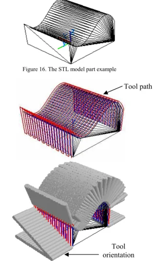
To implement the proposed method, this research demonstrates with an part example in STL model, as shown in Fig. 16. There are 233 triangular facets in this part model. Figure 17 shows the generated tool paths, as red trajectory, and tool orientations. The tool paths are generated with 5 mm path interval. The contour error comparisons for the 2nd tool path with 2 methods are shown in Fig. 18. The blue curve shows the contour error, using the conventional arithmetic mean tool orientation method. The max. error is 0.153mm by this method. The green curve is the proposed rotating angle adjustment method, according to the step length. The max. error in this case is 0.031mm. Clearly the conventional method generates the error about 5 times larger than the proposed one.
Figure 16. The STL model part example
Figure 17. Tool path and tool orientation for 5-axis machining
Cutting point
Conventional method Proposed method
5 10 15 20 25 30 35 40 45 50 55 60 0.2
.18
.16
.14
.12
0.1
.08 .06
.04
.02
0.0
Cont
ou
r e
rror (m
m
)
Figure 18. The contour errors for 2 different methods.
Tool path
Cutting points Path number Contour error (mm)
0.2 .18 .16 .14 .12 0.1 .08 .06 .04 .02 0.0
C
o
n
tou
r e
rro
r (
mm)
10 20 30 40 50 60 70
0 2 4 6 8 10 12 14
16 18 20
Figure 19. The contour errors for conventional method
Cutting points
Path number Contour error (mm)
Con
to
u
r err
o
r (mm)
.10 .09 .08 .07 .06 .05 .04 .03 .02 .01 .00
18
4 6 8 10
12 14 16
2 10
20 30 40 50 60
0
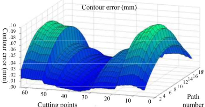
Figure 20. The contour errors for proposed method
Figure 19 shows the contour error for the entire part surface with respect to each tool path and cutting point, using the conventional method. The max. error is 0.165mm. Figure 20 presents the same error, using the proposed approach. The max. error is 0.082mm. Our approach not only improves the max. contour error, but smoothens the error on the part surface. Figure 21 shows the clear comparison, using these 2 methods. The abrupt error in red is using the conventional method, and the blue one is our approach.
Cutting points
10 20 30 40 50 60
Path number
5 10
15
0 .25
.20
.15
.10
.05
.00
Conto
u
r err
o
r (
mm)
Conventional method Proposed method
Figure 21. The contour errors for both methods, conventional method in red and proposed method in blue
V. CONCLUSIONS
The tool motion between 2 successive cutter contact points for five-axis machining makes a nonlinear trajectory and substantially causes overcuts or undercuts. The error between the desired trajectory and the actual tool path is called contour error. This error depends on the setup of the machine, the distance between the center of rotating axis and the workpiece, and the tool path step-size. This research
proposes a new method to produce accurate tool paths and orientations for 5-axis machining. The research approach begins with the analysis of the contour error due to the combinational motion of rotation and translation. The tool path step-size and tool orientation can be controlled accurately according to the pre-determined trajectory error. Taking a part for example, the result shows that the tool motion contour error is improved about 5 times, from 0.153 mm to 0.031 mm, by using conventional method and our proposed approach, respectively. The new method not only improves the max. contour error, but smoothens the error. In other words, this method improves both part accuracy and surface smoothness
ACKNOWLEDGMENT
The authors would like to acknowledge the financial support of the National Science Council, Taiwan, R.O.C. under the grant: NSC 100-2221-E-194 -006.
REFERENCES
[1] Balasubramaniam, M., Sarma, S. E. and Marciniak, K. “Collision-free finishing toolpaths from visibility data”, Computer-Aided Design, Vol. 35, 395-374, 2003.
[2] Chen, J.S, Huang, Y. K. and Chen, M. S. ”A study of the surface scallop generating mechanism in the ball-end milling process”, International Journal of Machine Tools & Manufacture, Vol. 45, pp.1077–1084, 2005. [3] Chui, K. L., Chiu, W. K. and Yu, K. M., “Direct 5-axis tool-path
generation from point cloud input using 3D biarc fitting”, Robotic and Computer-Integrated Manufacturing, Vol. 24, 270-286, 2008. [4] Choi, B. K., Park, J. W. and Jun, C. S., ”Cutter-location data optimization
in 5-axis surface machining”, Computer Aided Design ,Vol. 25, pp. 377-386, 1993.
[5] Ho, M.C. and Hwang, Y.R., “Machine Codes Modification Algorithm for Five-axis Machining,” Journal of Materials Processing Technology, Vol. 42, pp. 452-460, 2003.
[6] Ho, M. C. , Hwang ,Y. R. and Hu, C.H., “Five-axis tool orientation smoothing using quaternion interpolation algorithm”, International Journal of Machine Tools & Manufacture, Vol. 43, pp. 1259-1267, 2003. [7] Jensen, C. G. and Anderson, D. C., "Accurate Tool Placement and
Orientation for Finish Surface Machining", ASME Winter Annual Meeting, pp. 127-145, 1992.
[8] Lai, J.Y. and Wang, D.J. ,“Automatic Generation of NC Cutting Path for Sculptured Surfaces”, Journal of the Chinese Society of Mechanical Engineers, Vol. 15, No. 6,pp. 551-562, 1994.
[9] Loney , G. C. and Ozsoy , T. M., “NC machining of free form surfaces”, Computer Aided Design, Vol. 19, pp. 85-90, 1987.
[10] Lee, R.S. and She, C.H., “Developing a Postprocessor for Three Types of Five-axis Machine Tools,” International Journal of Advanced Manufacturing Technology, Vol. 13, pp. 658-665, 1997.
[11] Lin, R. S. and Koren, Y., Feb. 1996, “Efficient Tool-Path Planning for Machining Free-Form Surfaces,” ASME Journal of Engineering for Industry, Vol. 188, No.1, pp. 20-28.
[12] Sprow, Eugene E., "Set Up to Five-Axis Programming", Manufacturing Engineering, November, pp. 55-60, 1993
[13] Vickers, G. W. and Quan, K. W., "Ball-Mills Versus End-Mills for Curved Surface Machining", ASME Journal of Engineering for Industry, Vol. 111 Feb, pp. 22-26., 1989.