Earthquake Analysis of Multi Storied Residential Building - A
Case Study
E. Pavan Kumar
1, A. Naresh
2, M. Nagajyothi
3, M. Rajasekhar
41, 2(Student, Department of Civil Engineering, Vardhaman College of Engineering (Autonomous),
Hyderabad-501218)
3, 4
(Faculty, Department of Civil Engineering, Vardhaman College of Engineering (Autonomous), Hyderabad-501218)
ABSTRACT
Earthquake occurred in multistoried building shows that if the structures are not well designed and constructed with and adequate strength it leads to the complete collapse of the structures. To ensure safety against seismic forces of multi-storied building hence, there is need to study of seismic analysis to design earthquake resistance structures. In seismic analysis the response reduction was considered for two cases both Ordinary moment resisting frame and Special moment resisting frame. The main objective this paper is to study the seismic analysis of structure for static and dynamic analysis in ordinary moment resisting frame and special moment resisting frame. Equivalent static analysis and response spectrum analysis are the methods used in structural seismic analysis. We considered the residential building of G+ 15 storied structure for the seismic analysis and it is located in zone II. The total structure was analyzed by computer with using STAAD.PRO software. We observed the response reduction of cases ordinary moment resisting frame and special moment resisting frame values with deflection diagrams in static and dynamic analysis. The special moment of resisting frame structured is good in resisting the seismic loads.
Keywords
– Equivalent static analysis, response spectrum analysis, ordinary moment resisting frame, special moment resisting frame, STAAD.PRO V8i.I.
INTRODUCTION
At present people are facing problems of lad scarcity, cost of land. The population explosion and advent of industrial revolution led to the exodus of people from villages to urban areas i.e. construction of multi-storied buildings has become inevitable both for residential and as well as office purposes. The high raised structures are not properly designed for the resistance of lateral forces. It may cause to the complete failure of the structures. The earthquake resistance structures are designed based on the some factors. The factors are natural frequency of the structure, damping factor, type of foundation, importance of the building and ductility of the structure. The structures designed for ductility need to be designed for less lateral loads as it has better moment distribution qualities. This aspect is taken care of by response reduction factor R for different type of structure. For high performance, the building is designed as an SMRF. It needs to be designed only for lesser forces than it is designed as an OMRF.
1.1 MOMENT RESISTING FRAME:
The frame whose member and joints resist the forces primarily caused by flexure is Moment resisting frame.
1.1.1 Ordinary Moment Resisting Frame: The moment resisting frame which are designed without any special attention towards ductile nature of the frame are called ordinary moment resisting frames.
1.1.2 Special Moment Resisting Frame: The moment resisting frame which are designed to have ductile nature are called as special moment resisting frames. The design is done according to the requirements specified in IS-13920.
The earthquake resistant designs of structures are considering the following magnitudes of a earthquake.
1.2 Design Basis Earthquake (DBE): The earthquake whose probability of occurrence is at least one during the structure design life is called design basis earthquake.
1.3 Maximum Considered Earthquake (MCE): The earthquake whose expected intensity is maximum that can occur in a particular area or region is called maximum considered earthquake. The maximum values are considered as per code.
The design approach recommended by IS: 1893-2002 is based on the following principles (clause 6.1).
i. The structure should have the strength to withstand minor earthquakes less than DBE without any damage.
ii. The structure should be able to resist earthquakes equal to DBE without significant structural damage though some non-structural damage may occur.
iii. The structure should withstand an earthquake equal to MCE without collapse.
II.
METHODS
OF
ANALYSIS
2.1 Equivalent Static Analysis:
It is one of the method for calculating the seismic loads. The high rise structures are not considered for the design simple static method. In practical as it does not take into account all the factors that are the importance of the foundation condition. The equivalent static analysis is used to design only for the small structures. In this method only one mode is considered for each direction. The earthquake resistant designing for the low rise structures the equivalent static method is enough. Tall structures are needed more than two modes and mass weight of each story to design earthquake resistant loads. This is not suitable to design those structures and dynamic analysis method to be used for high rise structures.
2.2 Response Spectrum Analysis: The seismic forces strikes the foundation of a structure will move with the ground motion. It shows that structure movement is generally more than the ground motion. The movement of the structure as compared to the ground is refused as the dynamic amplification. It depends on the natural frequency of vibration, damping, type of foundation, method of detailing of the structure. The response “design acceleration spectrum” which refers to the max acceleration called spectral acceleration coefficient Sa/g, as a function of the structure for a specified damping ratio for earthquake excitation at the base for a single degree freedom system.
The revised IS 1893-2002 uses the dynamic analysis by response spectrum. In this method takes into account all the five important engineering properties of the structures.
i. The fundamental natural period of vibration of the building ( T in seconds)
ii. The damping properties of the structure iii. Type of foundation provided for the building iv. Imp0ortance factor of the building
v. The ductility of the structure represented by response reduction factor.
III.
ZONE
FACTORS
FOR
DIFFERENT
ZONES
IN
INDIA
Zone Seismic coefficient of 1984
Seismic zone factor (z of 2002)
V 0.08 0.36
IV 0.05 0.24
III 0.04 0.16
II 0.02 0.1
Table.1 Seismic Zone factors
IV.
MODAL GENERATION AND ANALYSIS:
We considered a residential building of 3BHK plan with y-axis consisted of G+15 floors. The ground floor and rest of the 15 floor had a height of 3m each. the supports at the base of the structure were also specified as fixed. The structure was subjected to self-weight, dead load, live load values considering by the specifications of IS 875 part-1 and part-2. The wind load values were generated by STAAD.PRO considering the given wind intensities at different heights and strictly abiding by the specifications of IS 875 part-3. The Seismic load calculations of Static and Dynamic analysis were done following IS 1893-2002 part-1.
Fig.1 column positions
Fig.3 Live load assigned in structure
Fig.4 axial force, shear force, torsion and diplacement
Fig.5 mode shape in dynamic analysis
Table 2. Axial forces in Static Analysis Static Analysis
Axial Force KN
BEAM L/C OMRF SMRF
36 1 EQ+X 3537.0 3916.4 99 1 EQ+X 3339.8 3663.0 162 1 EQ+X 3127.8 3409.7 225 1 EQ+X 2908.8 3156.5 288 1 EQ+X 2685.0 2903.6
Table 3. Torsion in Static Analysis Static Analysis
Torsion KNm
BEAM L/C OMRF SMRF
36 1 EQ+X -0.617 -0.059 99 1 EQ+X -1.520 -0.059 162 1 EQ+X -1.587 -0.059 225 1 EQ+X -1.643 -0.059 288 1 EQ+X -1.658 -0.058
Table 4. Bending Moment in Static Analysis Static Analysis
Bending moment-Z KNm
BEAM L/C OMRF SMRF
36 1 EQ+X 148.74 53.143 99 1 EQ+X 100.59 52.919 162 1 EQ+X 85.92 52.592 225 1 EQ+X 84.28 52.094 288 1 EQ+X 84.29 51.357
Table 5. Axial forces in Dynamic Analysis Dynamic Analysis
Axial Force KN
BEAM L/C OMRF SMRF
36 1 EQ+X 3541.9 4148.1 99 1 EQ+X 3336.8 3707.3 162 1 EQ+X 3117.2 3440.5 225 1 EQ+X 2894.1 3177.1 288 1 EQ+X 2669.2 2917.4
Table 6. Torsion in Dynamic Analysis Dynamic Analysis
Torsion KNm
BEAM L/C OMRF SMRF
Table 7.Bending Moment in Dynamic Analysis Dynamic Analysis
Bending moment-Z KNm
BEAM L/C OMRF SMRF
36 1 EQ+X 154.739 70.313 99 1 EQ+X 102.290 64.390 162 1 EQ+X 75.819 62.310 225 1 EQ+X 72.649 59.564 288 1 EQ+X 71.408 56.376
Table 8. Displacement X-trans in Static Analysis Static Analysis
Displacement X-Trans
BEAM L/C OMRF SMRF
36 1 EQ+X 1.849 0.456 99 1 EQ+X 13.455 2.107 162 1 EQ+X 26.684 4.433 225 1 EQ+X 39.456 7.025 288 1 EQ+X 50.163 9.624
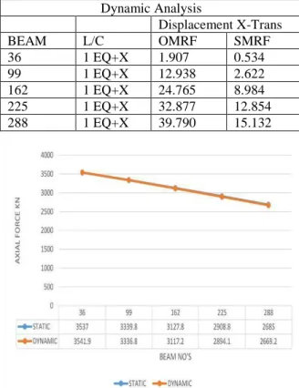
Table 9. Displacement X-Trans in DynamicAnalysis Dynamic Analysis
Displacement X-Trans
BEAM L/C OMRF SMRF
36 1 EQ+X 1.907 0.534 99 1 EQ+X 12.938 2.622 162 1 EQ+X 24.765 8.984 225 1 EQ+X 32.877 12.854 288 1 EQ+X 39.790 15.132
Graph 1. Static &dynamic analysis of axial forces in OMRF
Graph 2.static & dynamic analysis of Torsion in OMRF
Graph 3. Static & dynamic analysis of Bending Moment in OMRF
Graph 5. Static & dynamic analysis of Axial forces in SMRF
Graph 6. Static & dynamic analysis of Torsion in SMRF
Graph 7. Static & dynamic anlysis of Bending Moment in SMRF
Graph 8. Static & dynamic analysis of Displacement in SMRF
V.
CONCLUSION:
The obtained results of static and dynamic analysis in OMRF & SMRF are compared for different columns under axial, torsion, bending moment and displacement forces.
The results in graph-1 shows that there is equal values obtained of axial forces in static and dynamic analysis of OMRF structure. The results in graph-2 shows that the values are obtained for torsion in static analysis are negative and dynamic analysis values are positive. The results in graph-3 here we can observe that the values for bending moment at dynamic analysis values are high in initially for other columns it decreased gradually as compared to that of static analysis. The results in graph-4 we can observe that the values for displacement in static analysis of OMRF values are more compared to that of dynamic analysis values of same columns.
The results in graph-5 shows that the values obtained of axial forces in dynamic analysis of SMRF structure values are high compare to static analysis. The results in graph-6 shows that the values are obtained for torsion in static analysis are negative and dynamic analysis values are positive with more difference. In the results graph-7, we can observe that the values for bending moment at dynamic analysis values are more as compared to that of static analysis SMRF structure. In the results graph-8, we can observe that the values for displacement in dynamic analysis of SMRF values are gradually increased compared to that of static analysis values of same columns.
R
EFERENCES[1] Mohit Sharma, Dr. Savita Maru. IOSR Journal of Mechanical and Civil Engineering, Volume 11, Issue 1. Ver. II (Jan-2014), PP 37-42.
[2] IS: 1893-2002 (part-1) “criteria for earthquake resistant design of structures” fifth revision, Bureau of Indian Standards, New Delhi.
[3] IS: 456-2000 (Indian Standard Plain Reinforced Concrete Code of Practice) – Fourth Revision.
[4] IS: 875-1987 (part-1) for Dead Loads, code of practice of Design loads (other than earthquake) for buildings and structures. [5] IS: 875-1987 (part-2) for Live Loads or
Imposed Loads, code of practice of Design loads (other than earthquake) for buildings and structures.
[6] IS: 875-1987 (part-3) for Wind Loads, code of practice of Design loads (other than earthquake) for buildings and structures. [7] IS 13920-1993 for Ductile Detailing
Reinforced Concrete Structures subject to seismic forces, Bureau of Indian Standards, New Delhi.
[8] Dr. S.K Duggal, Earthquake Resistance Design of Structure.