Study of Strength of RC Shear Wall at Different Location on
Multi-Storied Residential Building
Syed Ehtesham Ali*, Mohd Minhaj Uddin Aquil**
*(Department of Civil Engineering, Assistant Professor Deccan college of Engineering and Technology, Hyderabad -01)
** (Department of Civil Engineering, Assistant Professor Deccan college of Engineering and Technology, Hyderabad -01
Abstract
Shear wall systems are one of the most commonly used lateral load resisting systems in high-rise buildings. Shear walls have very high in plane stiffness and strength, which can be used to simultaneously resist large horizontal loads and support gravity loads, making them quite advantageous in many structural engineering applications. There are lots of literatures available to design and analyze the shear wall. However, the decision about the location of shear wall in multi-storey building is not much discussed in any literatures. In this paper, therefore, main focus is to determine the solution for shear wall location in multi-storey building. A RCC building of six storey placed in HYDERABAD subjected to earthquake loading in zone-II is considered. An earthquake load is calculated by seismic coefficient method using IS 1893 (PART–I):2002. These analyses were performed using ETABS.
Keywords
: Multi-storey, RC structure, seismic analysis, RC shear wall, ETABS.I.
Introduction
Generally shear wall can be defined as structural vertical member that is able to resist combination of shear, moment and axial load induced by lateral load and gravity load transfer to the wall from other structural member. Reinforced concrete walls, which include lift wells or shear walls, are the usual requirements of Multi Storey Buildings. Design by coinciding centroid and mass center of the building is the ideal for a Structure. An introduction of shear wall represents a structurally efficient solution to stiffen a building structural system because the main function of a shear wall is to increase the rigidity for lateral load resistance.
In modern tall buildings, shear walls are commonly used as a vertical structural element for resisting the lateral loads that may be induced by the effect of wind and earthquakes which cause the failure of structure as shown in figure Shear walls of varying cross sections i.e. rectangular shapes to more irregular cores such as channel, T, L, barbell shape, box etc. can be used. Provision of walls helps to divide an enclose space, whereas of cores to contain and convey services such as elevator. Wall openings are inevitably required for windows in external walls and for doors or corridors in inner walls or in lift cores. The size and location of openings may vary from architectural and functional point of view.
The use of shear wall structure has gained popularity in high rise building structure, especially in the construction of service apartment or office/ commercial tower. It has been proven that this
system provides efficient structural system for multi storey building in the range of 30-35 storey’s (MARSONO & SUBEDI, 2000). In the past 30 years of the record service history of tall building containing shear wall element, none has collapsed during strong winds and earthquakes (FINTEL, 1995).
1.1 RC Shear Wall
Reinforced concrete (RC) buildings often have vertical plate-like RC walls called Shear Walls in addition to slabs, beams and columns. These walls generally start at foundation level and are continuous throughout the building height. Their thickness can be as low as 150mm, or as high as 400mm in high rise buildings. The overwhelming success of buildings with shear walls in resisting strong
earthquakes is summarized in the quote, “We cannot
afford to build concrete buildings meant to resist severe earthquakes without shear walls.” as said by Mark Fintel, a noted consulting engineer in USA.
RC shear walls provide large strength and stiffness to buildings in the direction of their orientation, which significantly reduces lateral sway of the building and thereby reduces damage to structure and its contents. Since shear walls carry large horizontal earthquake forces, the overturning effects on them are large. Shear walls in buildings must be symmetrically located in plan to reduce ill-effects of twist in buildings. They could be placed symmetrically along one or both directions in plan. Shear walls are more effective when located along
exterior perimeter of the building such a layout increases resistance of the building to twisting.
1.2 Function of Shear Wall
Shear walls must provide the necessary lateral strength to resist horizontal earthquake forces. When shear walls are strong enough, they will transfer these horizontal forces to the next element in the load path below them. These other components in the load path
may be other shear walls, floors, foundation walls, slabs or footings. Shear walls also provide lateral stiffness to prevent the roof or floor above from excessive side-sway. When shear walls are stiff enough, they will prevent floor and roof framing members from moving off their supports. Also, buildings that are sufficiently stiff will usually suffer less non-structural damage.
II.
Analysis
Analysis of building is done using ETABS. The models were prepared in the ETABS. Software by using different cross sections of RC shear wall viz. Box type, L type and cross type shear wall and these are located at different location such as along periphery, at corner and at middle positions.
2.1 Problem Statement
For the analysis purpose, the model of RC
building G+ 5 storey’s and 16mx16m plan area has
selected which is located in Hyderabad City. The ground storey height is 3.5m and floor to floor height is 3m. Spacing of frame is 4m. Concrete used is M20 and structural steel
is Fe415.
Structural properties of RC Building Shear wall
thickness : 200 mm
Total depth of
slab : 120 mm
External wall
thickness : 250 mm including plaster Internal wall : 150 mm including plaster
thickness Size of external
column : 300x530 mm Size of
internal
column : 300x300 mm Size of beam
in
longitudinal : 300x450 mm and transverse
direction Zone factor
(Z) : 0.1
Importance
factor (I) : 1 Response
reduction
factor (R) : 5
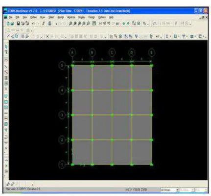
Fig. 1 Model of Building without shear wall
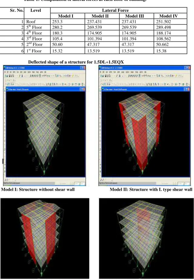
Table 1: Computation of lateral forces at each floor of building.
Sr. No. Level Lateral Force
Model I Model II Model III Model IV
1 Roof 253.3 237.431 237.431 251.502
2 5th Floor 280.2 269.539 269.539 289.498 3 4th Floor 180.3 174.905 174.905 188.174 4 3rd Floor 105.4 101.394 101.394 108.562 5 2nd Floor 50.60 47.317 47.317 50.662 6 1st Floor 15.32 13.519 13.519 15.38
Deflected shape of a structure for 1.5DL+1.5EQX
Model I: Structure without shear wall Model II: Structure with L type shear wall
III.
Result Summary
Table 4.1: Maximum Deflection at the Roof without Shear Wall.
software Load combination Calculated deflection (mm) ETABS 1.5DL+1.5EQX 51
1.2DL+1.2LL+1.2EQX 40
1.5DL+1.5EQZ 37
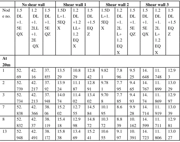
Table 4.2: Comparison of drift (mm) between shear wall and
Without shear wall of a structure.
No shear wall Shear wall 1 Shear wall 2 Shear wall 3
Nod 1.5 1.2 1.5 1.5D 1.2 1.5 1.5D 1.2 1.5 1.5 1.2 1.5 e no. DL DL DL L+1. DL DL L+1. DL DL DL DL DL +1. +1. +1. 5EQ +1.2 +1.5 5EQ +1. +1. +1. +1. +1.5 5E 2LL 5E X LL+ EQ X 2L 5E 5E 2L EQ QX +1. QZ 1.2 Z L+ QZ QX L+ Z
2E EQ 1.2 1.2
QX X EQ EQ
X X
At
20m
1 52. 42. 37. 13.5 10.8 12.8 9.82 7.8 9.5 14. 11. 12.9
69 16 855 29 29 42 1 96 25 648 748 3 2 52. 42. 37. 13.9 11.1 12.8 9.78 7.7 9.4 14. 11. 13.0
739 217 92 24 87 91 1 95 65 767 899 29 3 52. 42. 37. 14.0 11.4 13.4 9.70 7.7 9.4 14. 11. 12.9
734 213 948 74 02 02 8 85 93 74 869 97 7 52. 42. 38. 15.2 12.7 14.5 10.1 8.6 9.9 14. 11. 13.0
838 366 06 02 55 84 95 28 714 919 39 8 52. 42. 38. 15.4 12.9 14.8 10.3 8.8 10. 14. 11. 12.9
832 37 119 18 98 72 72 39 162 599 711 81 13 52. 42. 38. 15.8 13.4 15.2 10.6 9.1 10. 14. 11. 13.0
948 491 172 38 69 41 55 97 391 723 806 27
Table 4.3: Maximum Bending Moment of Various Models.
LEVEL Bending Moment (kN.M)
MODEL I MODEL II MODEL III MODEL IV
AT 20m -7.896 -10.607 17.207 -12.129
AT 8m -2.365 -2.132 12.412 -5.204
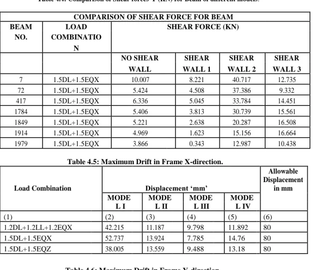
Table 4.4: Comparison of Shear forces-Y (KN) for Beam of different models.
COMPARISON OF SHEAR FORCE FOR BEAM
BEAM LOAD SHEAR FORCE (KN)
NO. COMBINATIO
N
NO SHEAR SHEAR SHEAR SHEAR
WALL WALL 1 WALL 2 WALL 3
7 1.5DL+1.5EQX 10.007 8.221 40.717 12.735
72 1.5DL+1.5EQX 5.424 4.508 37.386 9.332
417 1.5DL+1.5EQX 6.336 5.045 33.784 14.451 1784 1.5DL+1.5EQX 5.406 3.813 30.739 15.561 1849 1.5DL+1.5EQX 5.221 2.638 20.287 16.508 1914 1.5DL+1.5EQX 4.969 1.623 15.156 16.664 1979 1.5DL+1.5EQX 3.866 0.343 12.987 10.438
Table 4.5: Maximum Drift in Frame X-direction.
Load Combination Displacement ‘mm’
Allowable Displacement
in mm
MODE MODE MODE MODE
L I L II L III L IV
(1) (2) (3) (4) (5) (6)
1.2DL+1.2LL+1.2EQX 42.215 11.187 9.798 11.892 80 1.5DL+1.5EQX 52.737 13.924 7.785 14.76 80 1.5DL+1.5EQZ 38.005 13.559 9.488 13.18 80
Table 4.6: Maximum Drift in Frame Y-direction.
Load Combination Displacement ‘mm’ Allowable
MODE MODE MODE MODEL Displacement
L I
L II
L
III IV in mm
(1) (2) (3) (4) (5) (6)
1.2DL+1.2LL+1.2EQX 42.215 11.187 9.798 11.892 80 1.5DL+1.5EQX 52.737 13.924 7.785 14.76 80 1.5DL+1.5EQZ 38.005 13.559 9.488 13.18 80
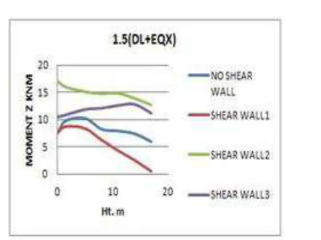
4.3. c: Graph of Bending Moment Y 4.4.d: Graph of Bending Moment Z
IV.
Discussion
4.1 Maximum DeflectionThe lateral deflection of column in the model of shear wall provided along periphery is reduced as compared to other two models. It reduces up to 33.31% and 32.03% as compared to models with L type shear wall and cross type shear wall respectively.
Maximum Shear Force in Beams
The effect of earthquake for model III at ground storey is more as compare to top storey and middle level. e.g. for a particular beam at ground storey increases shear force up to 21.20% compared to shear wall at middle storey.
Maximum Bending Moment in Beams
The effect of earthquake for model III at top storey is more as compare to middle storey and ground level. e.g. for a particular beam at top storey increases bending moment up to 41.60% compared to bending moment at middle store.
Fig: Plan of Building With Axial load on Columns
Fig: Plan of Building with Max Bending Moment in Beam.
V.
Conclusion
(i) Among all the load combination, the load combination of 1.5DL+1.5EQX is found to be more critical combination for all the models. (ii) The lateral deflection of column for building
with type 2 shear wall is reduced as compared to all models.
(iii) The shear force is maximum at the ground level for model III as compared to model II and IV.
(iv)The shear force of model IV at middle level is more as compared to model III.
(v) The bending moment is maximum at roof level for model III.
(vi)It has been observed that the top deflection is reduced after providing type 2 shear wall of the frame in X-direction as well as in Y-direction.
References
[1] Solution of shear wall in multi-storey
building”, Anshuman, Dipendu Bhunia,
Bhavin Ramjiyani, International journal of civil and structural engineering, Volume 2, no.2, 2011.
[2] “Review on Shear wall for soft storey high rise building, Misam Abidi and Mangulkar Madhuri N. ,International Journal of Civil and Advance Technology, ISSN 2249-8958,Volume-1,Issue-6,
August 2012
[3] “Effect of change in shear wall location on storey drift of multi-storey residential building subjected to lateral load”,
Ashish S. Agrawal and S. D. Charkha, International journal of Engineering Research and Applications, Volume 2, Issue 3,may-june 2012, pp.1786-1793. [4] “Configuration of multi-storey building
subjected to lateral forces”, M Ashraf, Z.
A. Siddiqui, M. A. Javed, Asian journal of civil engineering ,vol. 9,no.5, pp. 525-535, 2008.
[5] IS 1893(part 1) : 2002, “ Criteria for earthquake resistant design of structures, part 1, general provisions and buildings
“, Fifth revision, Bureau of Indian
Standerds, Manak Bhavan, Bahadur Shah Zafar Marg, New Delhi 110002.
[6] IS: 875 (Part 2) – 1987 (Reaffirmed
2008), “Code of practice for design loads for buildings and structures. Part 2- Imposed load”.
[7] Shrikhande Manish, Agrawal
Pankaj(2010).”Earthquake Resistant
Design of Structures.” PHI Learning
Private Limited New Delhi.
[8] Amit.V.Khandve,“Seismic Response of RC Frame Buildings with Soft Storeys”.
[9] Dr. Saraswati Setia and Vineet Sharm, “Seismic Response of R.C.C Building with Soft Storey”