Use of Woven Fabrics for Strengthening of Reinforced Concrete
Beams
Parthraj R. Puranik*, Deval A. Vasavada**, Dr. Vinu R. Patel***
*(Department of Textile Engineering, the Maharaja Sayajirao University of Baroda, Vadodara-1)
** (Asso. Prof., Department of Textile Engineering, the Maharaja Sayajirao University of Baroda, Vadodara-1) *** (Asst. Prof., Department of Applied Mechanics, The Maharaja Sayajirao University of Baroda, Vadodara-1)
ABSTRACT
Worldwide, a great deal of research is currently being conducted concerning the use of fiber reinforced plastic wraps, laminates and sheets in the repair and strengthening of reinforced concrete (RC) members. Fibre-reinforced polymer (FRP) application is a very effective way to repair and strengthen structures that have become structurally weak over their life span. But the use of woven fabrics for strengthening RC members has not been much investigated. Woven fabrics though cannot provide compressive strength, but have a great potential to provide bending or tensile strength to RC beams. In the present investigation, three different woven fabrics were used to strengthen RC beams. The aim is to study the effectiveness of woven fabric in strengthening of RC beams and the effect of number of fabric layers on load carrying capacity of RC beams.
Keywords
– Load-bearing capacity, reinforced concrete beams, repair and rehabilitation, strengthening, woven fabricsI.
INTRODUCTION
The maintenance, rehabilitation and upgrading of structural members, is perhaps one of the most crucial problems in civil engineering applications. Moreover, a large number of structures constructed in the past using older design methods in different parts of the world are structurally unsafe according to the new design methods. Since replacement of such deficient elements of structures incurs a huge amount of public money and time, strengthening has become the acceptable way of improving their load carrying capacity and extending their service lives. Infrastructure decay caused by premature deterioration of buildings and structures has led to the investigation of several processes for repairing or strengthening purposes. One of the challenges in strengthening of concrete structures is selection of a strengthening method that will enhance the strength and serviceability of the structure while addressing limitations such as constructability, building operations and budget. Structural strengthening may be required due to:
Additional strength may be needed to allow for higher loads to be placed on the structure. Strengthening may be needed to allow the
structure to resist loads that were not anticipated in the original design.
Additional strength may be needed due to a deficiency in the structure's ability to carry the original design loads.
The majority of structural strengthening involves improving the ability of the structural
element to safely resist one or more of the following internal forces caused by loading: flexure, shear, axial, and torsion. Strengthening is accomplished by either reducing the magnitude of these forces or by enhancing the member's resistance to them. One of the method of strengthening or repair and rehabilitation of RC structures is external bonded reinforcement. External bonded reinforcement includes bonding using steel plates or FRP sheets or woven fabrics.
The bonding of steel plates, using epoxy resins, to the tension zone of concrete beams is a method of improving structural performance. The technique is effective and has been used extensively in the rehabilitation of bridges and buildings. However, corrosion of the steel plates can cause deterioration of the bond at the glued steel-concrete interface, and consequently, render the structure vulnerable to loss of strength and possible collapse. Other disadvantages include difficulty of steel plates in shaping, weight of the plates makes them difficult to handle and transport, limited length of around 6m is available, so joints are required and this process is relatively time consuming and labour intensive.
To overcome these disadvantages of steel plate bonding, FRP sheets are used for bonding. Unidirectional FRP sheets made of carbon (CFRP), glass (GFRP) or aramid (AFRP) fibers bonded together with a polymer matrix are being used as a substitute for steel. FRP sheets offer immunity to corrosion, a low volume to weight ratio, and eliminate the need for the formation of joints due to
the practically unlimited delivery length of the composite sheets. Unlike steel, FRPs are unaffected by electrochemical deterioration and can resist the corrosive effects of acids, alkalis, salts and similar aggressive materials under a wide range of temperatures. With the exception of glass fiber composites, FRPs generally exhibit excellent fatigue and creep properties and require less energy per kilogram to produce and transport than metals. As a result of easier installation in comparison to steel, less site disruption should be experienced in the process, allowing faster and more economical strengthening.
The drawbacks are the intolerance to uneven bonding surfaces which may cause peeling of the plate, the possibility of brittle failure modes and the material cost, since fiber composites are between 4 – 20 times as expensive as steel in terms of unit volume. This is where a woven fabric can be advantageous.
The advantages and disadvantages associated with FRP sheets are also valid for woven fabrics, but it has some additional advantages. Woven fabrics can be engineered according to the need of the situation, wide variety of weaves and yarns are easily available, machines for manufacturing woven fabrics are well-known and time tested, technical staff is easily available and the cost of manufacturing is reasonably less than FRP.
II.
E
XPERIMENTALP
ROGRAMIn the experimental investigation, fabrics were made using Steel/PES blended spun yarn, cotton doubled spun yarn and polypropylene multifilament yarn. Yarn properties are given in the table 1. The fabrics were made on CCI sample weaving machines. The fabric details are given the fig. 1. Fabric testing was carried out on Lloyd LRX testing machine and results were obtained for maximum load, maximum extension, stiffness and stress.
Table 1: Properties of Yarns used to make Fabrics
Figure 1: Fabrics prepared for the investigation
Reinforced concrete beams were designed using M20 grade concrete and Fe 415 grade steel. Total nine beams were prepared with two steel bars of 10mm diameter as bottom reinforcement and two steel bars of 8mm diameter as top reinforcement. Stirrups were made with 6mm diameter steel bars. The dimensions of the beam were 1350mm x 150mm x 150mm. The reinforcement details are given in fig. 2. The beams were cured in a water tank for 28 days. After curing, three beams were tested directly with any strengthening and six beams were strengthened with woven fabric.
Figure 2: Reinforcement details of RC beams
Bonding Procedure
Before bonding the fabric to the RC beam surface, the surface of the beam was properly cleaned. Then epoxy adhesive (Araldite and Hardener) was mixed in accordance with the manufacturer’s instructions. Mixing was carried out in a plastic container. The adhesive was uniformly applied on the concrete surface and then fabric was spread over it. Then again a layer of adhesive was applied. Care was taken to eliminate bubbles present between the layers. These beams were cured for 24 hrs at room temperature.
Experimental Set-up
The Hydraulic Universal Testing Machine (UTM) with maximum capacity of 50tons (500kN) was used for testing all the specimens. A schematic view of the experimental set-up and the arrangement of the measurement devices are shown in fig. 3. Beams were tested under one-point loading. The load is applied at the midpoint of the beam. The span length of the beam is 1290mm and is the same for all specimens.
Steel/PES Double Yarn Warp Steel/PES Single Yarn Weft
epi x ppi = 50 x 44
Cotton Double Yarn Warp Steel/PES Single Yarn Weft
epi x ppi = 50 x 44
Polypropylene Yarn Warp Polypropylene Yarn Weft
Figure 3: Experimental Test Set-up
III.
T
HEORETICALC
ALCULATIONSFigure 4: Stress-Strain Diagram of Beam without Strengthening
The moment of resistance and estimated load carrying capacity of reinforced concrete beam without fabric wrapping are obtained from the following calculations:
Characteristic strength of concrete, = 20 MPa or 20 N/mm2,
Breadth, b = 150mm,
Depth of bottom reinforcement, d = 140mm Length of beam, L = 1350mm
Characteristic strength of steel, = 415 N/mm2, Area of steel reinforcement at bottom, = 157.08 mm2
As per IS : 456 : 2000, the total force due to compression (C) is equal to the total force due to tension (T), hence
C = T
0.36 x x x b = 0.87 x x = 52.51mm
= 0.36 x x x b (d – 0.42 x ) = 6.69kN.m
Hence, the moment of resistance of beam without fabric wrapping is 6.69kN.m.
For one point loading, the estimated load (P) can be given as,
= 19.82kN
Hence, the estimated load carrying capacity of beam without fabric wrapping is 19.82 kN.
Figure 5: Stress-Strain Diagram of Strengthened Beam
Now, considering the effect of strengthening of beam using one layer of woven fabric, so along with the tensile force an additional tensile force will also be acting. The value of = x , i.e. stress of fabric x area of fabric. The value of is obtained from the experimental testing.
C = T C = +
0.36 x x x b = 0.87 x x + ( x ) From the above formula, we obtain the value of . By using this value we obtain the values of and P. The calculated values are tabulated below:
Table 2: Maximum Load-carrying Capacity of Beams
IV.
R
ESULTS ANDD
ISCUSSIONA. Fabric Testing
This section describes the results of the various tests carried out on woven fabrics before and after application of adhesive.
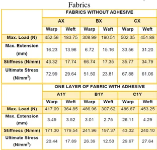
The fabric testing was carried out on Lloyd LRX testing machine. The testing speed was set to 100 mm/min for all the samples. Gauge length was set to 100mm. The results obtained from the tests carried out on fabrics without applying adhesive are tabulated below:
On applying adhesive to a single layer of fabrics, the warp-way strength of Steel/PES fabric and Polypropylene fabric decreased slightly than the original fabric without adhesive. Cotton Steel/PES fabric showed an increase in warp-way strength of more than 50%. The weft-way strength of Steel/PES fabric and Cotton Steel/PES fabric increased by about 100% and 60% respectively. The Polypropylene fabric showed a slight decrease in strength. By bonding two layers of fabrics with adhesive, the strength of all the fabrics became double then the single layer of fabric with adhesive.
The maximum extension of single layer of fabrics dropped significantly after applying adhesive. The Steel/PES and Cotton Steel/PES fabric showed a drop in extension by 60 – 80%. The Polypropylene fabric showed a drop in warp-way and weft-way extension by 25% and 85% respectively. By bonding two layers of fabrics with adhesive, all the samples except the warp-way Polypropylene sample showed a slight increase in extension. The warp-way Polypropylene sample showed a drop in extension by 35%. This may be due to the slippage of fabric layers during the tests.
Almost all the one layer fabric samples after adhesive application showed a significant increase in the stiffness. An increase of more than 200% was recorded for all samples except warp-way Polypropylene fabric which showed an increase of only 20%. The stiffness of all the two layer adhesive bonded samples almost doubled than single layer adhesive fabric.
The ultimate stress of all the fabrics reduced on application of adhesive. More than 50% drop in ultimate stress was recorded for all the samples. The ultimate stress of two layer Steel/PES fabric showed a further drop. But for the other two samples the ultimate stress showed slight increase.
A. Beam Testing
All the beams were tested up to ultimate failure. Initially, a single beam without fabric wrapping was tested. This beam was taken as control beam. In SET I, three beams with a single layer of each of the three fabrics were tested. In SET II, three beams with two layers of each of the three fabrics
were tested. It was observed that the control beam had less load carrying capacity when compared to that of the externally strengthened beams using woven fabrics. Deflection behavior and the ultimate load carrying capacity of the beams were noted.
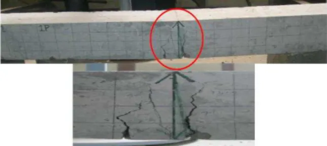
Figure 6: Flexural Failure of Control Beam and Developed Cracks
It was found that the control beam failed in flexure, with cracks developing near the point of application of load. A maximum load of 32kN was recorded for this beam. On trying to increase the load further, the crushing of concrete started to take place. (Fig. 6)
Figure 7a: Flexural Failure and Rupture of Fabric of Beam A1Y
In the beam A1Y, failure occurred due to simultaneous flexural failure of beam and rupture of fabric at the places of developed cracks. As the applied load was increased the cracks broadened and ultimately the beam failed completely recording ultimate load of 52kN. The failure of beam along with rupture of fabrics can be related to the extension at maximum and stiffness of the fabrics. The maximum extension of Steel/PES fabric was reduced by 80% and the stiffness increased by more than 200%. Also, the adhesive was able to give a strong bonding between the concrete surface and fabric, so simultaneous failure of both took place. (Fig. 7a)
For the beam A2Y, failure took place due to flexural failure of beam and fabric rupture. But the maximum load recorded was 41kN, lower than one layer wrapping. The beam was able to sustain higher curvature. (Fig. 7b)
Figure 8a: Flexural Failure and Rupture of Fabric of Beam B1Y
In the beam B1Y, same phenomenon was observed as one layer wrapping of Steel/PES fabric. Maximum load of 52kN was recorded for this beam. (Fig. 8a)
Figure 8b: Flexural Failure and Rupture of Fabric of Beam B2Y
The beam B2Y showed a drop in maximum load carrying capacity. It was recorded to about 38kN. This was due to very high stiffness and very low extension. (Fig. 8b)
Figure 9a: Flexural Failure and Debonding of Fabric of Beam C1Y
For the beam C1Y, the failure took place due to flexural failure of beam and delamination of the fabric from the concrete surface, but no cracks were observed on the fabric surface, i.e. there was no rupture of the fabric. As the applied load was increased, crushing of concrete started to take place,
with further debonding of the fabric. Ultimate load of 51kN was recorded. But, due to debonding of the fabric, the beam was able to sustain more bending, i.e. the curvature observed was very high. This also shows that the adhesive was not able to give a strong bond between the concrete surface and fabric. (Fig. 9a)
Figure 9b: Flexural Failure and Debonding of Fabric of Beam C2Y
In beam C2Y, same phenomena as one layer wrapping was observed and no drop in either load or curvature was recorded. The ultimate load recorded was 51kN. (Fig. 9b)
The ultimate load carrying capacity of all the beams along with the nature of failure is given in table:
Table 4: Ultimate Load and Nature of Failure of Beams
Load Deflection Behavior
than the control beams. The mid-span deflections were much lower when bonded externally with fabrics. The use of fabrics had effect in delaying the growth of crack formation.
Figure 10: Comparative Graph of Control Beam and Beams with One Layer of Fabric
The control beam failed at 32kN load, recorded deflection at maximum load of 5.90mm. The beam A1Y, the deflection exceeded 10mm after 49kN. At 32kN, it showed a deflection of 4.76mm, which is 20% less than the control beam. The beam B1Y, the deflection exceeded 10mm after 51kN. At 32kN, it showed a deflection of 3.58mm, which is 40% less than the control beam. The beam C1Y, the deflection exceeded 10mm after 50kN. At 32kN, it showed a deflection of 3.25mm, which is 45% less than the control beam.
Figure 11:Comparative Graph of Control Beam and Beams with Two Layers of Fabric
The beam A2Y, at 32kN showed a deflection of 3.28mm, which is 45% less than the control beam and 30% less than the beam A1Y. The beam B2Y, at 32kN showed a deflection of 3.97mm, which is 23% less than the control beam and 10% more than the beam B1Y. The beam C2Y, at 32kN showed a deflection of 3.80mm, which is 35% less than the control beam and 17% more than the beam C1Y.
Load at Initial Crack
One-point static loading was done on all the beams and at each increment of load; deflection and crack development were observed. The load at initial crack of all the beams was observed, recorded and is shown in Fig. 12.
Figure 12: Graph Showing Load at Initial Crack
Ultimate Load Carrying Capacity
The load carrying capacity of the control beams and the strengthened beams were found out and is shown in Fig. 13. The control beam was loaded up to the ultimate loads. It was noted that, all the strengthened beams had higher load carrying capacity compared to the control beam. But it was found that the load carrying capacity of beams wrapped with one layer of fabric was higher than the beams wrapped with two layers of fabric. The reasons for this have already been discussed. The use of fabric can delay the initial cracks and further development of the cracks in the beam.
Figure 13: Ultimate Load Carrying Capacity of Beams
Figure 14: Comparison of Analytical and Experimental Load Carrying Capacity
V.
C
ONCLUSION1. Use of three types of fabrics as repair and rehabilitation strengthening of RCC beam shows similar improvement in ultimate load bearing capacity; it is an alternative to conventional methods of strengthening of RCC beam.
2. Single wrapping gives almost 50% improvements in ultimate load bearing capacity, with all three types of fabrics. As per the literature available for similar application with GFRP, the improvement is comparable. However, double wrapping does not give expected rise in ultimate load bearing capacity, because of increase in fabric stiffness around the beam as it limits deflection of beam.
3. With PP x PP variety both single and double wrapping showed debonding leaving center of the beam to deflect freely. It questions the use of PP x PP variety with the adhesive employed for this testing.
4. Onset of initial crack is delayed with all three types of fabrics, suggesting its utility in enhancing beam’s utility in carrying the load. 5. The analytical technique can predict exact
increase in the strength due to wrapping provided appropriate grade of concrete casting materials are used.
R
EFERENCES[1] Handbook on Repair and Rehabilitation of RCC Buildings, by Central Public Works Department (CPWD).
[2] Yoshiki Tanaka, Jun Murakoshi and Eiji Yoshida, Load Carrying Capacity of Reinforced Concrete Beams with Adhesively Bonded Steel Plates, Public Works Research Institute, Japan.
[3] Kris Brosens and Sven Ignoul, Strengthening of Concrete Structures with Externally Bonded Reinforcement – Case Studies, BVSM, Leuven, November 2000. [4] Nishikant Dash, Strengthening of
Reinforced Concrete Beams using Glass
Fibre Reinforced Polymer Composites, ME Thesis, NIT Rourkela, 2009.
[5] Seema Bhagat and Jyoti Bhusari, Improving Shear Capacity of RC Beams using Epoxy Bonded Continuous Steel Plates, International Journal of Advanced Technology in Civil Engineering, Vol. 2, Issue 1, 2013.
[6] ACI 440 Committee, State-of-the-Art Report on Fibre Reinforced Plastic (FRP) Reinforcement for Concrete Structures, ACI, 2002.
[7] R. Balamuralikrishnan and Antony Jeyasehar, Flexural Behaviour of RC Beams Strengthened with Carbon Fibre Reinforced Polymer (CFRP) Fabrics, The Open Civil Engineering Journal, Vol. 3, pg. 102 – 109, 2009.
[8] Ahmed Khalifa, Abdeldjelil Belarbi and Antonio Nanni, Shear Performance of RC Members Strengthened with Externally Bonded FRP Wraps, WCEE, 2000.
[9] K.L. Muthuramu, A. Chandran, S. Govindarajan and S. Karunanidhi, Strengthening of Reinforced Concrete Elements using Glass Fibre, 35th Conference on Our World in Concrete and Structures, Aug. 2010.
[10] Joseph W. Tedesco, J. Michael Stallings and Mahmoud EL-Mihilmy, Rehabilitation of a Reinforced Concrete Bridge using FRP Laminates, Final Report, The Alabama Department of Transportation, March 1998. [11] M.A.A. Saafan, Shear Strengthening of
Reinforced Concrete Beams using GFRP Wraps, Acta Polytechnica, Vol. 46, Issue 1, 2006.
[12] Hau-yan Leung, Effect of Woven Fabric on the Shear Capacity of Short RC Beams, Journal of Civil Engineering and Management, Vol. IX, Issue 3, pg. 172 – 177, 2003.