ANNALS OF THE UNIVERSITY OF ORADEA FASCICLE OF TEXTILES, LEATHERWORK
THE METHOD OF DESIGNING ASSISTED ON COMPUTER OF THE
FOOTWEAR’S SOLES
LUCA Cornelia
1, IONESCU Cozmin
21“
Gheorghe Asachi” Technical University of Iasi, Faculty Textile Leather and Management Industry, Bd. Dimitrie Mangeron 28 Postal code 70050,Iaşi, Romania, E-mail: [email protected]
2“
Gheorghe Asachi” Technical University of Iasi, Doctoral School of Faculty Textile Leather and Management Industry, Bd. Dimitrie Mangeron 28 Postal code 70050,Iaşi, Romania, E-mail: [email protected]
Corresponding author: Luca Cornelia, E-mail: [email protected]
Abstract: To the base of the footwear soles designing, is the shoe last. The shoe lasts have irregular shapes, with various curves witch can’t be represented by a simple mathematic function. In order to design the footwear’s soles it’s necessary to take from the shoe last some base contours. These contours are obtained with high precision in a 3D CAD system. In the paper, it will be presented a method of designing of the soles for footwear, computer assisted. The copying process of the shoe last is done using the 3D digitizer. For digitizing, the shoe last spatial shape is positioned on the peripheral of data gathering, witch follows automatically the shoe last’s surface. The wire network obtained through digitizing is numerically interpolated with the interpolator functions in order to obtain the spatial numerical shape of the shoe last. The 3D designing of the sole will be realized on the numerical shape of the shoe last following the next steps: the manufacture of the sole’s surface, the lateral surface realization of the sole’s shape, obtaining the link surface between the lateral side and the planner one of the sole, of the sole’s margin, the sole’s designing contains the skid proof area. The main advantage of the designing method is the design precision, visualization in 3D space of the sole and the possibility to take the best decision viewing the acceptance of new sole’s pattern.
Key words: footwear soles, moulds soles, CAD methods designing
1.
INTRODUCTION
To the base of the footwear soles designing, is the shoe last. Nowadays there are specialized soft equipped with the necessary parts to develop a designing activity, computer assisted that allow the introduction of the shoe last’s contour in 3D, dressing the shoe last in the footwear’s faces, designing the shoe last sole in 3 D, diversifying the sole’s patterns witch can be put on the same shoe last, the design of the matrix, obtaining and multiplying the samples necessary for the matrix execution, the 3D graphical visualization of the sole’s shapes and matrix, the determination of the polymeric jointing volumes necessary to obtain the soles in different numbers and sizes [1],[2]
In the paper, it will be presented a method of designing of the soles for footwear, computer assisted.
2. EXPERIMENTAL PART – CASE STUDY
2.1. The mathematic modeling and graphical visualization of the shoe last
To the sole’s designing for footwear, will be followed the next steps: the shoe last’s designing, the reconstruction of the shoe last dressed with the footwear faces, the sole’s drawing in 2 D, sole’s designing in 3 D, attaching the sole to the faces from the shoe last [3].
The shoe lasts have irregular shapes, with various curves witch can’t be represented by a simple mathematic function.
shape is positioned on the peripheral of data gathering, witch follows automatically the shoe last’s surface, drawing in the same time some curves on the shoe last [4], like in the Fig 1.
Fig. 1: The shoe last copy, drawing the curve network
The wire network obtained through digitizing is numerically interpolated with the interpolator functions in order to obtain the spatial numerical shape of the shoe last. The shoe last obtained is manufactured with soft systems in different shapes and colors to suggest as well as possible its spatial image [1],[5], like in the Fig 2 .
Fig. 2: The shoe last’s image manufactured with soft systems
2.2.
The reproduction of the shoe last dressed with the footwear’s faces in 3 D
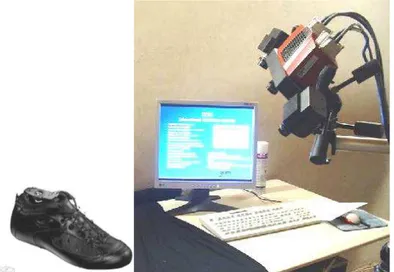
The reproduction in 3D of the shoe last witch is dressed with footwear’s faces, is made with a scanning machine 3D Atos which is integrated to the computer, like in the Fig.3.
Fig. 3: The copying process in 3 D of the shoe last with the faces pulled with the scanning machine
The shoe last dressed with the faces, as shown in Fig.3, is introduced in the scanning machine for copying. Before the introduction, on the faces are applied different types of adhesives.
ANNALS OF THE UNIVERSITY OF ORADEA FASCICLE OF TEXTILES, LEATHERWORK
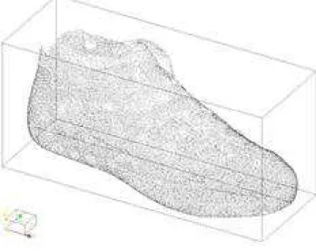
the entire volume. The pressing process and the gathering data one, starts from one of the limit parts of the shoe last, it continues with the planner area that with the other limit part until the shoe last comes in the horizontal position. To the copying process a lot of attention needs to be accorded to the area that marks the shoe lasts edge where the faces have been pulled, because this area is hard to be recognized by the machine. The numerical data gathered through pressing, are introduced simultaneously in the computer’s program as a point cloud of the pressed shape [1], [3]. The resulted shape is represented in the Fig 4.
Fig 4: The copied shape as a point cloud
The 3 D designing of the sole will be realized on this shape from, following the next steps: the manufacture of the sole’s surface, the lateral surface realization of the sole’s shape, obtaining the link surface between the lateral side and the planner one of the sole, of the sole’s margin, the sole’s designing contains the skid proof area [6],[7].
In Fig. 5 is presented the 2D model of a bicolor soles to be projected 3D according to the method of work.
Fig 5: The sole’s designing in 2D
2.3. Designing the sole’s planner surface
of the surface [1],[4].
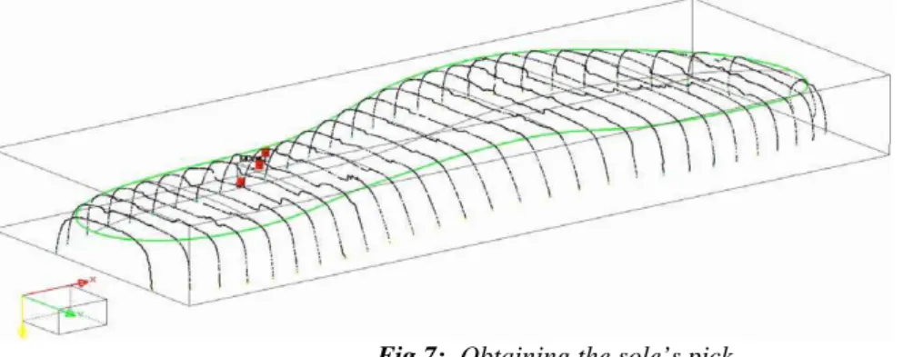
Fig 7: Obtaining the sole’s pick
The transversal sections are realized from the point cloud, the plans parallel and equidistant direct on the planner surface of the shape in the Fig 5. These sections that have been drawn through points have to be corrected. So, there are constructed Spline curves, which have to cut the imperfections. On the Spline curves corrected, is drawn the planner surface of the sole from the Fig.8.
Fig 8: The planner surface of the sole that comes in contact with the shoe last
After drawing this surface, it is analyzed again and where has appeared inequalities between the parallel sections of the sole’s surface, are done point corrections.
2.4. Designing the lateral surface of the sole
So created the planner surface, next to be constructed will be the sole’s lateral surface [1],[9]. This construction will be realized on the network from the Fig 5, following the next steps:
- In the first step is being obtained a section in the upper area of the shape hence will be constructed a 2D Spline curve line. The shape is sectioned with radial plans, are obtained point lines that are constructed Spline curves witch serve to generate the lateral surface. Not all the sections are used in the surface construction. The density of necessary sections will be directly proportioned with the surface complexity. So, for the heel and toe areas will be necessary more sections and for the rest of the surfaces will be necessary fewer sections.
ANNALS OF THE UNIVERSITY OF ORADEA FASCICLE OF TEXTILES, LEATHERWORK
have to be corrected, it can be modified the control points of the surface. In the end is obtained the contour like in the Fig 9.
Fig9: Realizing the lateral surface of the sole’s shape
Obtaining the link surface between the lateral side and the planner one of the sole, the sole’s margin, is realized through the intersection of the points that pass through its planner surface of the lateral shape and surface
In the Fig 10 have been represented point sections with surfaces and cloud point with surfaces.
Fig.10: Point sections and cloud point with surfaces
In this step was realized the mathematic pattern of the shape, obtaining the shape in 3D, it represents the intermediary phase when the mathematic pattern of the product has been realized. This pattern will be used forward to obtain the sole’s exact pattern.
2.5. Designing the exterior sole, with skid proof area
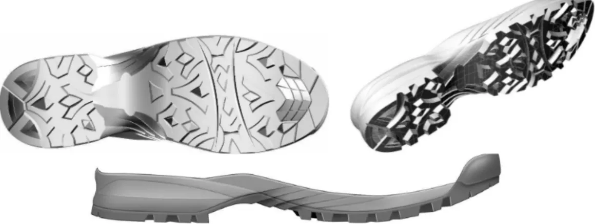
The exterior sole is designed [1],[4] on the fond surface in the Fig 10 using 3D Spline functions, like in the Fig 11.
Fig 11: The sole’s drawing with skid proof area Fig 12: Separating the two soles
As the sole is bicolor, it will be considered that the interior sole the one without the skid proof area and the exterior sole that has skid proof area. Being obtained both soles mono-block, it can be studied the evolution of the surfaces that limit the two soles by introducing some sections in the important points that separate them , like in the Fig 12.
Fig 13: The final shape of the sole in 3 D
3. CONCLUSIONS
The main advantages of the presented design method are:
• design precision,
• visualization in 3D space of the sole,
• the possibility to take the best decision viewing the acceptance of new sole’s pattern.
REFERENCES
[1] C. Ionescu Luca and R. Mocanu R., “Proiectarea matriţelor pentru încãlţãminte, Elemente de proiectare geometricã a tãlpilor matriţate”, Editura Pim Iaşi, 2010, ISBN 978-606-13-0100-3 [2] Drişcu, M. “Modelling of Planar and Spatial Forms of Footwear”, In Romanian, Pim Press Iaşi, 2008, ISBN 978-606-520-233-7.
[3] M. Cocea, “Generating the digital spatial surface a last”, Bulletin of the Polytechnic Institute of Iasi, Tome LI (LV), Section Mechanical Engineering, ISSN 1011-2855, 2006.
[4] M.Cocea and M. Bălăşescu, “The spatial modeling of footwear products”, Revista Meridian Ingineresc, nr. 1, p.42, Editura Tehnica-Info Chişinău, ISSN 1683-853X, 2005.
[5] Aplicaţii ATOS- scanere 3D. [Online]. Available: http://www.scanare3d.com
[6] A. Mihai, M. Şahin, M. Pãştinã and M.C. Harnagea, “Proiectarea încãlţãmintei”, Editura Performantica Iaşi, ISBN:978-973-730-465-6, 2009
[7] E. Chirilã and C. Ionescu Luca, “Solutions of the different models of cavities for soles obtaining”, Annals of the University of Oradea, fascicle of Textiles-Leatherwork, volume IX, p.236-240, ISSN 1582-5590, 2008.
[8] A. Dragomir and C. Ionescu Luca, “Contributions à la projection spatiale “3D” des semelles, des talons et des cavités des matrices pour l’industrie de chaussures”, Buletinul I.P.Iaşi, Tomul LIV(LVIII), Fasc. 1-3, Secţia Construcţii de maşini, p. 333-337, ISSN 1011-2855. Iasi, Romania, 2008.