Amita Baghel.et.al. Int. Journal of Engineering Research and Application www.ijera.com
ISSN : 2248-9622, Vol. 7, Issue 2, ( Part -2) February 2017, pp.48-51
www.ijera.com DOI: 10.9790/9622-0702024851 48 |P a g e
Best Position of R.C. Shear Wall due to seismic loads
Amita Baghel, Urvashi Kesharwani, Gourav Sachdeva
BE –scholar Department of Civil Engineering St. Aloysius Institute of Technology Jabalpur BE –scholar Department of Civil Engineering St. Aloysius Institute of Technology Jabalpur Assistant Professor Department of Civil Engineering St. Aloysius Institute of Technology Jabalpur
ABSTRACT
A shear wall is a wall that is designed to resist shear, the lateral force that causes the bulk of damage in earthquakes. Many building codes mandate the use of such walls to make homes safer and more stable. In this work, a G+2 storey R.C. building frame has been considered and analyzed for seismic zone-lll(Jabalpur) using staad.prov8i (series4) package, special moment resisting frame (SMRF) and hard rock types used in work. Parameters are taken to compare and analyze for the results are Node displacement and Reactions for different arrangements
Keywords: Shear Wall, Staad Pro. V8i (Series 4), SMRF, Maximum node displacement & Maximum reactions.
I.
INTRODUCTION
Shear walls are efficient, both in terms of construction cost and effectiveness in minimizing earthquake damage in structural elements. Shear walls are vertical elements of the horizontal force resisting system. Shear walls are constructed to counter the effects of lateral load acting on a structure also these walls provide large strength and stiffness to buildings in the direction of their orientation, which significantly reduces lateral sway of the building and thereby reduces damage to structure and its contents. The use of any software example, STAAD-PRO.will make it easier. Hence, this paper has been described to determine the proper location of shear wall.
II.
LOADING CONSIDERATION
Loads Acting On The Structure Are:
Dead Load (DL) and Live load (LL) : As per IS 875 (Part 1) (1987) and IS 875 (Part 2) (1987), respectively.
Seismic load (SL): As per IS 1893 (Part 1) (2002) approach.
DL :Dead load
● Self weight of the structure, ● Floor load and
● Wall loads
LL :Live load
● 3 KN/sq.m is considered for floor load ● 1 KN/sq.m considered for floor finish
SL: Zone : III (Z=0.16) Rock/ soil type : Hard Rock and Soil site factor : 1 Response reduction factor : 5 Importance factor : 1 Damping : 5%
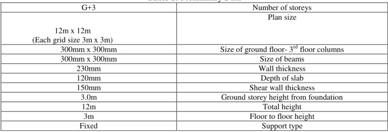
The preliminary data as is taken up for this study
Table 1: Preliminary Data
Number of storeys G+3
Plan size
12m x 12m (Each grid size 3m x 3m)
Size of ground floor- 3rd floor columns 300mm x 300mm
Size of beams 300mm x 300mm
Wall thickness 230mm
Depth of slab 120mm
Shear wall thickness 150mm
Ground storey height from foundation 3.0m
Total height 12m
Floor to floor height 3m
Support type Fixed
III.
Literature Review
A lot of research work has been done in
the direction of shearwall multistory building. Arvind Vinaya krao Achole, Dr.G.N. Rong he
Amita Baghel.et.al. Int. Journal of Engineering Research and Application www.ijera.com
ISSN : 2248-9622, Vol. 7, Issue 2, ( Part -2) February 2017, pp.48-51
www.ijera.com DOI: 10.9790/9622-0702024851 49 |P a g e studied the behavior of building frame with steel
plate shearwalls. Dr.SudhirK.Jain and Dr.H.J.Shahgave notes on design examples of a six storey building. Alfa Rasikan (2013), M.G. Rajendran(2013) analyzed Wind behavior of buildings with and without shearwall. Ashis Debashis Behera, K.C. Biswalstudied3-D analysis of building frame using staadpro. Prashanth.P (2012), Anshuman.S (2012), Pandey.R.K(2012), ArpanHerbert(2012)Compareddesignresultsofa Structure designed using STAAD and ETABS Software. However the work on shearwall most efficient location has not been done much.
IV.
OBJECTIVE OF STUDY
1) To analyze an R.C. building frame using staad pro. Software setup.
2) To understand the purpose of using shear walls using staad pro. for future purpose.
3) To compare the effect of an R.C. shear walls when provided at different locations. on an R.C. Building.
4) To study the results of node displacement and maximum reactions obtained.
V.
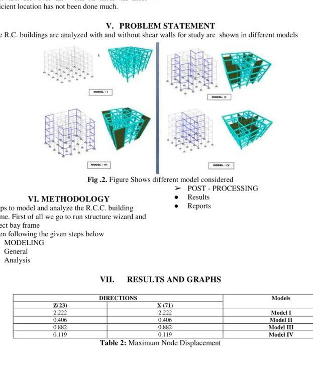
PROBLEM STATEMENT
The R.C. buildings are analyzed with and without shear walls for study are shown in different models
Fig .2. Figure Shows different model considered
VI.
METHODOLOGY
Steps to model and analyze the R.C.C. building frame. First of all we go to run structure wizard and select bay frame
Then following the given steps below
➢ MODELING
● General ● Analysis
➢ POST - PROCESSING ● Results
● Reports
VII.
RESULTS AND GRAPHS
Models DIRECTIONS
X (71) Z(23)
Model I
2.222 2.222
Model II
0.406 0.406
Model III
0.882 0.882
Model IV
0.119 0.119
Amita Baghel.et.al. Int. Journal of Engineering Research and Application www.ijera.com
ISSN : 2248-9622, Vol. 7, Issue 2, ( Part -2) February 2017, pp.48-51
www.ijera.com DOI: 10.9790/9622-0702024851 50 |P a g e
A) MAXIMUM NODE DISPLACEMENT:
Fig .2.Figure Shows node no. 71&23
A) MAXIMUM REACTION:
Table 3: Maximum Reaction
Models Directions
X(51) Z(3)
Model I
2.668 2.668
Model II
1.560 1.560
Model III
2.629 2.629
Model IV
68.234 68.234
Amita Baghel.et.al. Int. Journal of Engineering Research and Application www.ijera.com
ISSN : 2248-9622, Vol. 7, Issue 2, ( Part -2) February 2017, pp.48-51
www.ijera.com DOI: 10.9790/9622-0702024851 51 |P a g e
Fig.6. Max. Reaction in x- direction Fig.7. Max. Reaction in z- direction
VIII.
DISCUSSION
A) Maximum Node Displacement- In this
analysis the variation of maximum node displacement is found to be reduced when shear walls were provided. The least values of the same were found are 0.119& 0.119 in X-direction & Z- X-direction respectively for Model-IV w.r.t. Model-I.this work was done for X & Z direction at node no.7 & 23 respectively. These nodes are selected on the basis of maximum node displacement obtained w.r.t model-I.
B) Maximum Reaction-It is found that the
model-IV is much effective than othermodels. For model-IV the reaction either in x& z direction are foundmaximum i.e. 68.234 KN,68.234KN respectively . For nodes 51&3, this work is done in x&z directionsrespectively. These nodes are selected on the basis of maximum reaction obtained w.r.t model-I.
IX.
CONCLUSION
A) Node Displacement: Maximum node
displacement was found on top floor of the structure at node no.71 & 23. Model- IV gives the minimum value of maximum node displacement in x & z direction hence Model IV is best position for the same .
B) Maximum Reaction: Model IV is much more
effective than others, such thatthemaximum reaction values found for all x & z directions having node no. 51&3. Hence model IV is best position for the same.
REFERENCES
[1]. Building Seismic Safety Council, NEHRP Recommended Provisions for Seismic Regulations for New Buildings and Other Structures, FEMA 368, Washington, D.C. March 2001.
[2]. Sachdeva Gaurav, Jain Rajesh “3D Analysis of building
frame using Staad Pro.” NIT ROURKELA”
[3]. AshishDebashisBehera, K.C. Biswal ”3D Analysis of
building frame using Staad Pro.” NIT ROURKELA
[4]. IS: 1893-2002 (part-1) “criteria for earthquake resistant
design of structures” fifth revision, Bureau of Indian
Standards, New Delhi.
[5]. IS: 875-1987 (part-2) for Live Loads or Imposed Loads, code practice of Design loads (other than earthquake) for buildings and structures
[6]. Bureau of Indian Standards: IS:875-1987, (part 1), Dead Loads on Buildings and Structures, New Delhi, India. [7]. Dr. Sudhir K Jain (IIT Kanpur) and Dr. H.J.Shah
(M.S.University of Baroda, Vadodara) “Design
Example of a Six Storey Building” IITK
-GSDMA-EQ26- V3.0
[8]. NaumanMohammed , Islam Nazrul “Behaviour of
Multistorey RCC Structure with Different Type of
Bracing System” Structure engineer. December 2013.
[9]. Viswanath K.G, Prakash K.B and Desai Anant,
“Seismic Analysis of Steel Braced Reinforced Concrete Frames”, International Journal of civil and structural